
Installation instructions
Audi Universal T
raffic Recorder
Audi Q3 (8U) 2015 ►
Audi Q5 (8R) 2013 ►
For scope of delivery
4G0.063.511
Audi Genuine Accessories
Edition 01
Service
Service Department. Technical Information

Installation instructions
Audi Universal T
raffic Recorder
Audi Q3 (8U) 2015 ►
For scope of delivery
4G0.063.511
Audi Genuine Accessories
Edition 01
Service
Service Department. Technical Information

Contents
1 General notes . . . . . . . . . . . . . . . . . . . . . . . . . . . . . . . . . . . . . . . . . . . . . . . . . . . . . . . . . . . . . . . . . . . . . . . . . . . . . . . . . . . . . . . . . . . 1
2 Safety notes . . . . . . . . . . . . . . . . . . . . . . . . . . . . . . . . . . . . . . . . . . . . . . . . . . . . . . . . . . . . . . . . . . . . . . . . . . . . . . . . . . . . . . . . . . . . 2
2.1 General safety notes . . . . . . . . . . . . . . . . . . . . . . . . . . . . . . . . . . . . . . . . . . . . . . . . . . . . . . . . . . . . . . . . . . . . . . . . . . . . . . . . . . . . 2
3 Repair instructions . . . . . . . . . . . . . . . . . . . . . . . . . . . . . . . . . . . . . . . . . . . . . . . . . . . . . . . . . . . . . . . . . . . . . . . . . . . . . . . . . . . . 3
3.1 Contact corrosion . . . . . . . . . . . . . . . . . . . . . . . . . . . . . . . . . . . . . . . . . . . . . . . . . . . . . . . . . . . . . . . . . . . . . . . . . . . . . . . . . . . . . . . . 3
3.2 Routing and securing lines . . . . . . . . . . . . . . . . . . . . . . . . . . . . . . . . . . . . . . . . . . . . . . . . . . . . . . . . . . . . . . . . . . . . . . . . . . . . . 3
4 Overview of components, scope of delivery and overview of fitting location . . . . . . . . . . . . . . . . 4
4.1 Overview of components . . . . . . . . . . . . . . . . . . . . . . . . . . . . . . . . . . . . . . . . . . . . . . . . . . . . . . . . . . . . . . . . . . . . . . . . . . . . . . . 4
4.2 Scope of delivery . . . . . . . . . . . . . . . . . . . . . . . . . . . . . . . . . . . . . . . . . . . . . . . . . . . . . . . . . . . . . . . . . . . . . . . . . . . . . . . . . . . . . . . . 4
4.3 Overview of fitting location . . . . . . . . . . . . . . . . . . . . . . . . . . . . . . . . . . . . . . . . . . . . . . . . . . . . . . . . . . . . . . . . . . . . . . . . . . . . . . 5
5 Sequence of operations . . . . . . . . . . . . . . . . . . . . . . . . . . . . . . . . . . . . . . . . . . . . . . . . . . . . . . . . . . . . . . . . . . . . . . . . . . . . . . . 6
5.1 Preparations . . . . . . . . . . . . . . . . . . . . . . . . . . . . . . . . . . . . . . . . . . . . . . . . . . . . . . . . . . . . . . . . . . . . . . . . . . . . . . . . . . . . . . . . . . . . . 6
5.2 Connecting the UTR wiring harness – left-hand drive vehicle . . . . . . . . . . . . . . . . . . . . . . . . . . . . . . . . . . . . . . . 6
5.3 Installing the front camera . . . . . . . . . . . . . . . . . . . . . . . . . . . . . . . . . . . . . . . . . . . . . . . . . . . . . . . . . . . . . . . . . . . . . . . . . . . . . . 10
5.4 Assembling the vehicle . . . . . . . . . . . . . . . . . . . . . . . . . . . . . . . . . . . . . . . . . . . . . . . . . . . . . . . . . . . . . . . . . . . . . . . . . . . . . . . . . 11
Service
All rights reserved.
No reproduction without prior agreement from publisher.
Copyright © 2019 Audi AG, Ingolstadt
Printed in Germany

1 General notes
Please read these instructions carefully and note the Warning,
Caution and Note descriptions before installing the Audi Univer-
sal T
raffic Recorder.
WARNING
Text with this symbol contains information concerning
your safety and indicates potential accident and injury
risks.
Caution
Text with this symbol indicates the risk of damage to your
vehicle.
Note
Text with this symbol contains additional information.
Note
◆ The Audi Universal Traffic Recorder must be installed by a
qualified workshop. Special tools and supplementary vehi-
cle-specific literature will be needed to perform the installa-
tion. Improper installation can cause damage to the vehicle
or to the Audi Universal T
raffic Recorder.
◆ The work to be performed on the vehicle, as detailed in
these fitting instructions, may change as a result of meas-
ures to upgrade models. Consequently, modifications to con-
nectors, wire colours or even the fitting location, for instance,
should not be ruled out. For this reason, make sure that you
always refer to the most current wiring diagram and/or the
current repair manuals for the vehicle.
◆ We reserve the right to make technical changes.
Audi AG shall not accept responsibility in the event of fail-
ure to comply with these installation instructions.
Installation instructions - Audi Universal Traffic Recorder Audi Q3 (8U) 2015 ►
Edition 01
1 General notes
1

2 Safety notes
2.1 General safety notes
WARNING
Please read these installation instructions carefully be-
fore starting installation. Non-compliance with these in-
stallation instructions and safety notes will compromise
your safety and that of third parties.
WARNING
All mechanical and electrical connections must be
checked to make sure that they are positioned and instal-
led correctly.
WARNING
Repairs or the replacement of parts must only be per-
formed by a qualified workshop. It is recommended that
genuine spare parts available from your Audi partner are
used.
WARNING
The Audi Universal Traffic Recorder has no internal volt-
age source and is dependent on the on-board supply.
Installation instructions - Audi Universal Traffic Recorder Audi Q3 (8U) 2015 ►
Edition 01
2
2 Safety notes

3 Repair instructions
3.1 Contact corrosion
Contact corrosion can occur when unsuitable connecting ele-
ments (screws, nuts, washers) are used.
For this reason, only connecting elements with a special sur-
face coating are fitted.
Additionally, rubber or plastic parts and adhesives are made of
materials that are not electrically conductive.
If you are in any doubt about the suitability of parts, use new
parts as a general rule ⇒ Electronic parts catalogue.
Please note:
◆ We recommend using only genuine spare parts; these parts
have been tested and are compatible with aluminium.
◆ We recommend using Audi Genuine Accessories.
◆ Damage caused by contact corrosion is not covered by the
warranty
.
3.2 Routing and securing lines
WARNING
Observe the safety instructions for pyrotechnic compo-
nents (see repair group 69).
During installation, ensure that the airbag does not be-
come trapped. Route the retrofit wiring harness behind
the airbag and secure accordingly
. The airbag must be
able to function under all circumstances.
◆ To avoid damage to wires in the interior due to the limited
space available, make sure that there is adequate clearance
in relation to all moving components.
Installation instructions - Audi Universal Traffic Recorder Audi Q3 (8U) 2015 ►
Edition 01
3 Repair instructions
3

4 Overview of components, scope of delivery and overview
of fitting location
4.1 Overview of components
1 - Front camera
2 - Anti-glare film
4.2 Scope of delivery
4G0.063.511
Quantity Component
1 Front camera
1 Camera wiring harness with coupling point
1 Anti-glare film for front camera
1 Operating instructions
Installation instructions - Audi Universal Traffic Recorder Audi Q3 (8U) 2015 ►
Edition 01
4
4 Overview of components, scope of delivery and overview of fitting location

Not included in the scope of delivery, must be ordered separately: UTR wiring harness 4G0.063.511.C
Quantity Component
1 UTR wiring harness for the on-board supply
5 Cable tie N.020.904.5
3 Foam grommet 811.971.790
1 5 A fuse
2 Connector housing 1J0.972.751
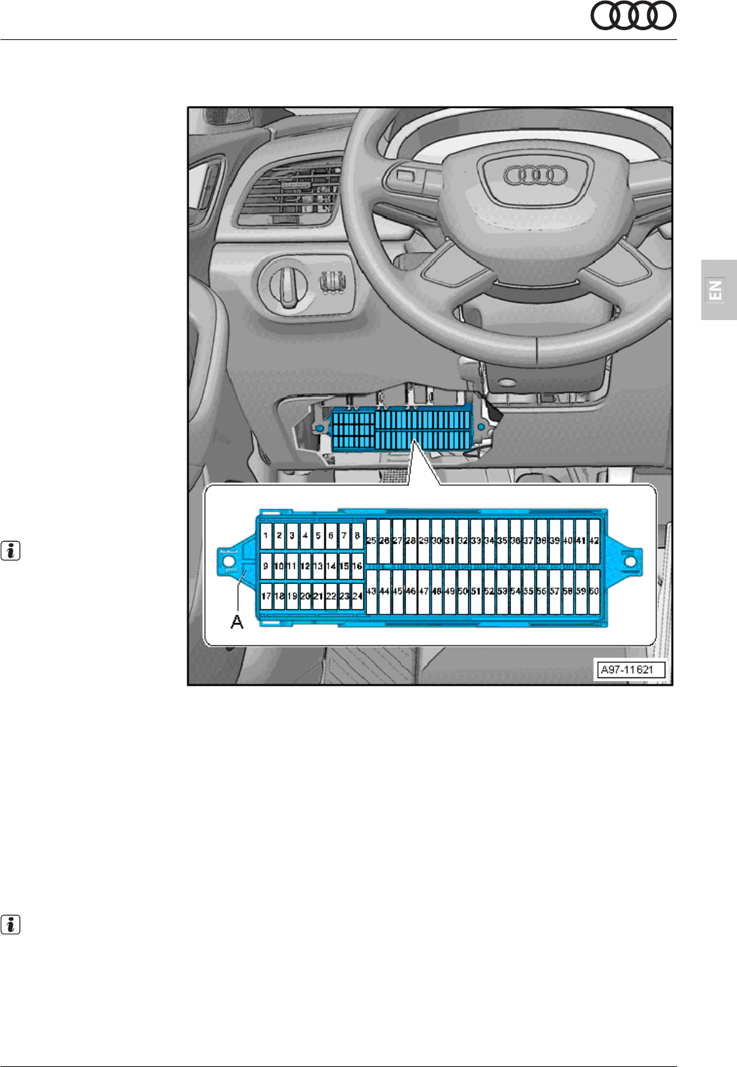
4.3 Overview of fitting location
Caution
This image shows the routing of the wiring harness for a left-hand drive vehicle. Connection in right-
hand drive vehicles is performed in a mirror-inverted sequence – risk of confusion!
A - Position of front cam-
era
B - Connection to on-
board supply
Installation instructions - Audi Universal Traffic Recorder Audi Q3 (8U) 2015 ►
Edition 01
4 Overview of components, scope of delivery and overview of fitting location
5

5 Sequence of operations
5.1 Preparations
ELSA reference
– Disconnect the battery⇒ Electrical system; Rep. gr. 27; Bat-
tery; Disconnecting and connecting the battery
– Remove the roof module⇒ Interior equipment; Rep. gr. 68;
Storage compartments, covers; Removing and installing the
roof module
– Remove the driver side sun visor⇒ Interior equipment; Rep.
gr. 68; Equipment; Removing and installing the sun visor
– Remove the A-pillar trim on the driver side⇒ General body
repairs, interior; Rep. gr. 70; Interior trims; Removing and in-
stalling the A-pillar trim
– Remove the footwell trim on the driver side⇒ General body
repairs, interior; Rep. gr. 68; Interior trims; Removing and in-
stalling the footwell trim
– Remove the sill panel trim on the front driver side⇒ General
body repairs, interior; Rep. gr. 70; Interior trims; Removing
and installing the sill panel trim
5.2 Connecting the UTR wiring harness –
left-hand drive vehicle
WARNING
Observe the safety instructions for pyrotechnic compo-
nents (see repair group 69).
Caution
This chapter describes the routing of the UTR wiring har-
ness for a left-hand drive vehicle. Connection in right-hand
drive vehicles is performed in a mirror-inverted sequence –
risk of confusion!
Note
◆ Make sure that all routed wires are long enough to reach the
installation position.
◆ Make sure that the wire for the mounting base of the front
camera is long enough for it to be attached at the installation
position.
◆ Remove any trim parts to determine the correct wire length.
Routing the camera wiring harness
– Loosen the headliner slightly across the entire area of the
windscreen so that the camera wiring harness can be fed
through more easily.
– Carefully route the camera wiring harness through the roof
module opening and further on between the windscreen and
Installation instructions - Audi Universal Traffic Recorder Audi Q3 (8U) 2015 ►
Edition 01
6
5 Sequence of operations

the headliner towards the front in the direction of the front
camera installation position and leave it hanging there.
– Secure the camera wiring harness coupling point with a
foam grommet to prevent noises from developing.
– Connect the UTR wiring harness for the on-board supply to
the camera wiring harness coupling point.
Routing the UTR wiring harness for the on-board supply
– Route the entire UTR wiring harness under the headliner to
the A-pillar on the driver side.
– If necessary, fasten the individual wires in the area of the
headliner together using fabric tape to prevent noises from
developing.
– Route the UTR wiring harness further downwards from the
A-pillar to the fuse holder
-C-SC- on the left-hand side, next
to the steering column.
– Fix the UTR wiring harness in place on the standard wiring
harness using fabric tape to prevent noises from developing.
Installation instructions - Audi Universal Traffic Recorder Audi Q3 (8U) 2015 ►
Edition 01
5 Sequence of operations
7

Connecting terminal 30 (red) of the UTR wiring harness for the on-board supply to the fuse holder
-C-SC-
– Unpin the standard wir-
ing harness on fuse
carrier -C-SC-
-A- from
the following chamber:
◆ Compartment C30
– Pin unpinned contact
-C30- into the connec-
tor housing supplied
(1J0.972.751) and in-
sert into the corre-
sponding connector on
the UTR wiring har-
ness.
– Pin the free wire (red)
on the UTR wiring har-
ness into free chamber
-C30-.
Installation instructions - Audi Universal Traffic Recorder Audi Q3 (8U) 2015 ►
Edition 01
8
5 Sequence of operations
Connecting terminal 15 (green) of the UTR wiring harness for the on-board supply to fuse holder
-C-SC-
– Unpin the standard wir-
ing harness on fuse
carrier -C-SC-
-A- from
the following chamber:
◆ Compartment C37
– Pin unpinned contact
-C37- into the connec-
tor housing provided
(1J0.972.751) and in-
sert into the corre-
sponding connector on
the retrofit cable har-
ness.
– Pin the free wire
(green) on the UTR
wiring harness into free
chamber -C37-.
– Secure the earth wire
(black) of the UTR wir-
ing harness at the
earth point in the area
of the A-pillar in the
left-hand footwell.
Note
The earth point should be
selected based on the ca-
ble length.
– If all connection work
has been completed,
fix the coupling point of
the roof module in
place so that no noise is generated and nothing is disturbed during the installation of the roof module.
Applies to vehicles that are not equipped with a CD player
◆ Compartment C37 (not assigned)
– Pin the free wire (green) on the UTR wiring harness into free chamber -C37-.
– Fix the remaining plug-in connector on the UTR wiring harness and secure to prevent noises from devel-
oping.
– Insert the 5-A fuse.
– Secure the earth wire (black) of the UTR wiring harness at the earth point of the A-pillar in the left-hand
footwell.
Note
The earth point should be selected based on the cable length.
– If all connection work has been completed, fix the coupling point of the roof module in place so that no
noise is generated and nothing is disturbed during the installation of the roof module.
Installation instructions - Audi Universal Traffic Recorder Audi Q3 (8U) 2015 ►
Edition 01
5 Sequence of operations
9
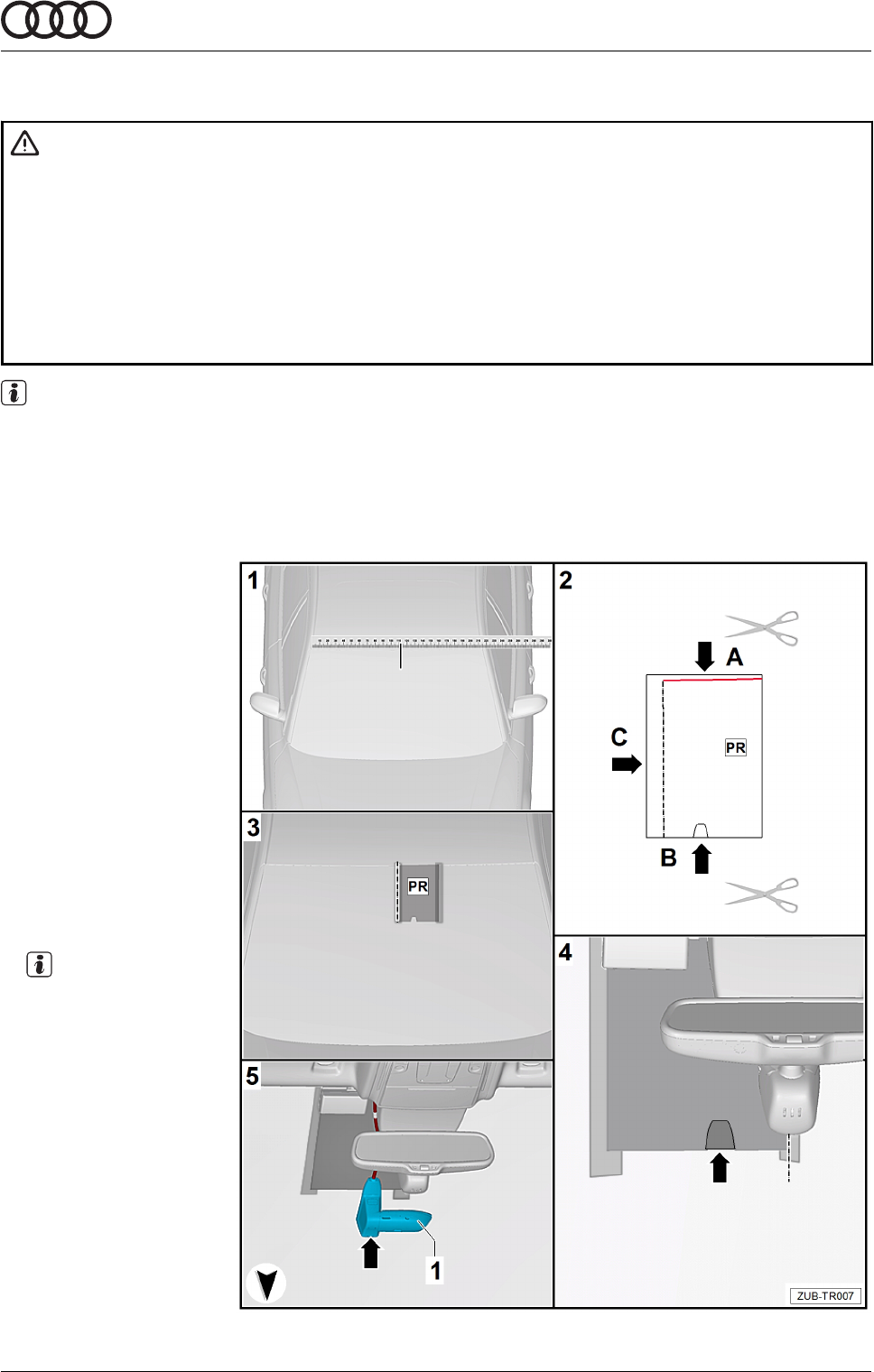
5.3 Installing the front camera
WARNING
The appendix of the fitting instructions contains a template for positioning the anti-glare film sup-
plied for the front camera.
Print out the template.
The template features a positioning mark. Using a ruler, measure the positioning mark. This must
be 10 cm.
If the dimension is too small or large, the printer options must be changed from “Fit” to “Actual
size”.
Note
◆ Install the front camera only in the specified area of the windscreen.
◆ Before fitting the front camera, thoroughly clean the windscreen using workshop tools.
◆ The windscreen must be free from dust and grease.
Assembly sequence
Image 1 - From outside
the vehicle, deter-
mine the centre of the
windscreen and mark
this position.
Image 2 - Use the tem-
plate that corre-
sponds with the PR
number for the mirror
base equipment var-
iant and cut the tem-
plate along the dotted
line -arrow A- and
-arrow C-. Also cut
out the position of
the camera base
-arrow B-.
Note
Note the PR number of
the mirror base equip-
ment variant
⇒
table
shown below.
Installation instructions - Audi Universal Traffic Recorder Audi Q3 (8U) 2015 ►
Edition 01
10
5 Sequence of operations

Image 3 - Position the template in the centre and on the upper edge of the windscreen and fix it in
place using adhesive tape. The writing on the template must be the right way up facing outwards.
Remove the protective paper from the anti-glare film.
Image 4 - Position the anti-glare film -arrow- on the inside of the windscreen using the template and
carefully press it on.
Note
Starting in the middle, carefully press trapped air outwards using a squeegee or a cloth.
Image 5 - Clip the front camera -1- into the mounting base, position this on the inside of the wind-
screen on the anti-glare film -arrow- and carefully press it on.
Note
Assistance from a second technician is required to position the camera with precision.
Equipment variants
8N1 Intermittent windscreen wiper
8N6 Intermittent windscreen wiper with light/rain sensor
8N7 Intermittent windscreen wiper with light/rain sensor
QK0 No camera for assistance systems
QK1 Camera for assistance systems
5.4 Assembling the vehicle
– Connect the battery⇒ Electrical system; Rep. gr
. 27; Battery;
Disconnecting and connecting the battery
If the battery is being reconnected, the following steps
must be taken:
◆ Delete the fault memory.
◆ Activate the one-touch opening and closing of the electric
windows ⇒ operating instructions.
◆ Synchronise secondary and additional keys to ensure the re-
mote control functions correctly
. To do this, insert the key in-
to the ignition lock, switch the ignition on and off again and
then remove the key.
Note
After reconnecting the power supply, the ESP warning light can
only extinguish after a few metres have been driven.
– Perform a function test for the camera ⇒
UTR operating in-
structions
Installation instructions - Audi Universal Traffic Recorder Audi Q3 (8U) 2015 ►
Edition 01
5 Sequence of operations
11

Audi Q3 - AU316
QK1+8N1/8N6
QK1+8N7
QK0+8N1/8N6
QK0+8N7
STR
roof edge
roof edge
roof edge
roof edge
mid windscreen
mid windscreen
Check dimensional change!
Nominal size: 10cm
Note:
When printing this template don't
make any format adaption!

Installation instructions
Audi Universal T
raffic Recorder
Audi Q5 (8R) 2013 ►
For scope of delivery
4G0.063.511
Audi Genuine Accessories
Edition 01
Service
Service Department. Technical Information

Contents
1 General notes . . . . . . . . . . . . . . . . . . . . . . . . . . . . . . . . . . . . . . . . . . . . . . . . . . . . . . . . . . . . . . . . . . . . . . . . . . . . . . . . . . . . . . . . . . . 1
2 Safety notes . . . . . . . . . . . . . . . . . . . . . . . . . . . . . . . . . . . . . . . . . . . . . . . . . . . . . . . . . . . . . . . . . . . . . . . . . . . . . . . . . . . . . . . . . . . . 2
2.1 General safety notes . . . . . . . . . . . . . . . . . . . . . . . . . . . . . . . . . . . . . . . . . . . . . . . . . . . . . . . . . . . . . . . . . . . . . . . . . . . . . . . . . . . . 2
3 Repair instructions . . . . . . . . . . . . . . . . . . . . . . . . . . . . . . . . . . . . . . . . . . . . . . . . . . . . . . . . . . . . . . . . . . . . . . . . . . . . . . . . . . . . 3
3.1 Contact corrosion . . . . . . . . . . . . . . . . . . . . . . . . . . . . . . . . . . . . . . . . . . . . . . . . . . . . . . . . . . . . . . . . . . . . . . . . . . . . . . . . . . . . . . . . 3
3.2 Routing and securing lines . . . . . . . . . . . . . . . . . . . . . . . . . . . . . . . . . . . . . . . . . . . . . . . . . . . . . . . . . . . . . . . . . . . . . . . . . . . . . 3
4 Overview of components, scope of delivery and overview of fitting location . . . . . . . . . . . . . . . . 4
4.1 Overview of components . . . . . . . . . . . . . . . . . . . . . . . . . . . . . . . . . . . . . . . . . . . . . . . . . . . . . . . . . . . . . . . . . . . . . . . . . . . . . . . 4
4.2 Scope of delivery . . . . . . . . . . . . . . . . . . . . . . . . . . . . . . . . . . . . . . . . . . . . . . . . . . . . . . . . . . . . . . . . . . . . . . . . . . . . . . . . . . . . . . . . 4
4.3 Overview of fitting location . . . . . . . . . . . . . . . . . . . . . . . . . . . . . . . . . . . . . . . . . . . . . . . . . . . . . . . . . . . . . . . . . . . . . . . . . . . . . . 5
5 Sequence of operations . . . . . . . . . . . . . . . . . . . . . . . . . . . . . . . . . . . . . . . . . . . . . . . . . . . . . . . . . . . . . . . . . . . . . . . . . . . . . . . 6
5.1 Preparations . . . . . . . . . . . . . . . . . . . . . . . . . . . . . . . . . . . . . . . . . . . . . . . . . . . . . . . . . . . . . . . . . . . . . . . . . . . . . . . . . . . . . . . . . . . . . 6
5.2 Routing and connecting the retrofit wiring harness . . . . . . . . . . . . . . . . . . . . . . . . . . . . . . . . . . . . . . . . . . . . . . . . . . . 6
5.3 Assembling the vehicle . . . . . . . . . . . . . . . . . . . . . . . . . . . . . . . . . . . . . . . . . . . . . . . . . . . . . . . . . . . . . . . . . . . . . . . . . . . . . . . . . 8
5.4 Installing the front camera . . . . . . . . . . . . . . . . . . . . . . . . . . . . . . . . . . . . . . . . . . . . . . . . . . . . . . . . . . . . . . . . . . . . . . . . . . . . . . 9
5.5 Concluding operations . . . . . . . . . . . . . . . . . . . . . . . . . . . . . . . . . . . . . . . . . . . . . . . . . . . . . . . . . . . . . . . . . . . . . . . . . . . . . . . . . . 10
Service
All rights reserved.
No reproduction without prior agreement from publisher.
Copyright © 2019 Audi AG, Ingolstadt
Printed in Germany

1 General notes
Please read these instructions carefully and note the Warning,
Caution and Note descriptions before installing the Audi Univer-
sal T
raffic Recorder.
WARNING
Text with this symbol contains information concerning
your safety and indicates potential accident and injury
risks.
Caution
Text with this symbol indicates the risk of damage to your
vehicle.
Note
Text with this symbol contains additional information.
Note
◆ The Audi Universal Traffic Recorder must be installed by a
qualified workshop. Special tools and supplementary vehi-
cle-specific literature will be needed to perform the installa-
tion. Improper installation can cause damage to the vehicle
or to the Audi Universal T
raffic Recorder.
◆ The work to be performed on the vehicle, as detailed in
these fitting instructions, may change as a result of meas-
ures to upgrade models. Consequently, modifications to con-
nectors, wire colours or even the fitting location, for instance,
should not be ruled out. For this reason, make sure that you
always refer to the most current wiring diagram and/or the
current repair manuals for the vehicle.
◆ We reserve the right to make technical changes.
Audi AG shall not accept responsibility in the event of fail-
ure to comply with these installation instructions.
Installation instructions - Audi Universal Traffic Recorder Audi Q5 (8R) 2013 ►
Edition 01
1 General notes
1

2 Safety notes
2.1 General safety notes
WARNING
Please read these installation instructions carefully be-
fore starting installation. Non-compliance with these in-
stallation instructions and safety notes will compromise
your safety and that of third parties.
WARNING
All mechanical and electrical connections must be
checked to make sure that they are positioned and instal-
led correctly.
WARNING
Repairs or the replacement of parts must only be per-
formed by a qualified workshop. It is recommended that
genuine spare parts available from your Audi partner are
used.
WARNING
The Audi Universal Traffic Recorder has no internal volt-
age source and is dependent on the on-board supply.
Installation instructions - Audi Universal Traffic Recorder Audi Q5 (8R) 2013 ►
Edition 01
2
2 Safety notes

3 Repair instructions
3.1 Contact corrosion
Contact corrosion can occur when unsuitable connecting ele-
ments (screws, nuts, washers) are used.
For this reason, only connecting elements with a special sur-
face coating are fitted.
Additionally, rubber or plastic parts and adhesives are made of
materials that are not electrically conductive.
If you are in any doubt about the suitability of parts, use new
parts as a general rule ⇒ Electronic parts catalogue.
Please note:
◆ We recommend using only genuine spare parts; these parts
have been tested and are compatible with aluminium.
◆ We recommend using Audi Genuine Accessories.
◆ Damage caused by contact corrosion is not covered by the
warranty
.
3.2 Routing and securing lines
WARNING
Observe the safety instructions for pyrotechnic compo-
nents (see repair group 69).
During installation, ensure that the airbag does not be-
come trapped. Route the retrofit wiring harness behind
the airbag and secure accordingly
. The airbag must be
able to function under all circumstances.
◆ To avoid damage to wires in the interior due to the limited
space available, make sure that there is adequate clearance
in relation to all moving components.
Installation instructions - Audi Universal Traffic Recorder Audi Q5 (8R) 2013 ►
Edition 01
3 Repair instructions
3

4 Overview of components, scope of delivery and overview
of fitting location
4.1 Overview of components
1 - Front camera
2 - Anti-glare film
4.2 Scope of delivery
4G0.063.511
Quantity Component
1 Front camera
1 Camera wiring harness with coupling point
1 Anti-glare film for front camera
1 Operating instructions
Installation instructions - Audi Universal Traffic Recorder Audi Q5 (8R) 2013 ►
Edition 01
4
4 Overview of components, scope of delivery and overview of fitting location

Not included in the scope of delivery, must be ordered separately: UTR wiring harness 4G0.063.511.C
Quantity Component
1 UTR wiring harness for the on-board supply
5 Cable tie N.020.904.5
3 Foam grommet 811.971.790
1 5 A fuse
2 Connector housing 1J0.972.751
4.3 Overview of fitting location
Caution
This image shows the routing of the wiring harness for a left-hand drive vehicle. Connection in right-
hand drive vehicles is performed in a mirror-inverted sequence – risk of confusion!
A - Position of front cam-
era
B - Connection to on-
board supply
Installation instructions - Audi Universal Traffic Recorder Audi Q5 (8R) 2013 ►
Edition 01
4 Overview of components, scope of delivery and overview of fitting location
5

5 Sequence of operations
5.1 Preparations
ELSA reference
– Disconnect the battery⇒ Electrical system; Rep. gr. 27; Bat-
tery; Disconnecting and connecting the battery
– Remove the roof module⇒ Interior equipment; Rep. gr. 68;
Storage compartments, covers; Removing and installing the
roof module
– Remove the passenger side sun visor⇒ Interior equipment;
Rep. gr. 68; Equipment; Removing and installing the sun vi-
sor
– Remove the A-pillar trim on the passenger side⇒ General
body repairs, interior; Rep. gr. 70; Interior trims; Removing
and installing the A-pillar trim
– Remove the footwell trim on the passenger side⇒ General
body repairs, interior; Rep. gr. 68; Interior trims; Removing
and installing the footwell trim
5.2 Routing and connecting the retrofit wir-
ing harness
WARNING
Observe the safety instructions for pyrotechnic compo-
nents (see repair group 69)
Caution
This chapter describes the routing of the UTR wiring har-
ness for a left-hand drive vehicle. Connection in right-hand
drive vehicles is performed in a mirror-inverted sequence –
risk of confusion!
Note
◆ Make sure that all routed wires are long enough to reach the
installation position.
◆ Make sure that the wire for the mounting base of the front
camera is long enough for it to be attached at the installation
position.
◆ Remove any trim parts to determine the correct wire length.
Routing the camera wiring harness
– Loosen the headliner slightly across the entire area of the
windscreen so that the camera wiring harness can be fed
through more easily.
– Carefully route the camera wiring harness through the roof
module opening and further on between the windscreen and
the headliner towards the front in the direction of the front
camera installation position and leave it hanging there.
Installation instructions - Audi Universal Traffic Recorder Audi Q5 (8R) 2013 ►
Edition 01
6
5 Sequence of operations

– Secure the camera wiring harness coupling point with a
foam grommet to prevent noises from developing.
– Connect the UTR wiring harness for the on-board supply to
the camera wiring harness coupling point.
Routing the UTR wiring harness for the on-board supply
– Route the entire UTR wiring harness under the headliner to
the A-pillar on the passenger side.
– If necessary, fasten the individual wires in the area of the
headliner together using fabric tape to prevent noises from
developing.
– Route the UTR wiring harness downwards from the A-pillar
to the fuse holder
-D-SD- on the left-hand side, next to the
glove compartment.
Connecting terminal 15 (green) of the UTR wiring harness for the on-board supply to fuse carrier
-ST1-
– Unpin the standard wir-
ing harness on fuse
carrier -ST2- from the
following chamber:
◆ Compartment 11A
– Pin unpinned contact
-11A- into the connec-
tor housing supplied
(1J0.972.751) and in-
sert into the corre-
sponding connector on
the UTR wiring har-
ness.
– Pin the free wire
(green) on the UTR
wiring harness into free
chamber -11A-.
Installation instructions - Audi Universal Traffic Recorder Audi Q5 (8R) 2013 ►
Edition 01
5 Sequence of operations
7

Connecting terminal 30 (red) and the earth wire (black) of the UTR wiring harness for the on-board
supply to fuse carrier -ST1-
– Unpin the standard wir-
ing harness on fuse
carrier -ST1- from the
following chamber:
◆ Compartment 7A
– Pin unpinned contact
-7A- into the connector
housing supplied
(1J0.972.751) and in-
sert into the corre-
sponding connector on
the UTR wiring har-
ness.
– Pin the free wire (red)
on the UTR wiring har-
ness into free chamber
-7A-.
– Secure the earth wire
(black) of the UTR wir-
ing harness at the
earth point of the A-pil-
lar in the right-hand
footwell.
Note
The earth point should be
selected based on the ca-
ble length.
– If all connection work
has been completed,
fix the coupling point of
the roof module in
place so that no noise is generated and nothing is disturbed during the installation of the roof module.
5.3 Assembling the vehicle
– Reassemble the vehicle by following these steps in reverse
order.
Installation instructions - Audi Universal Traffic Recorder Audi Q5 (8R) 2013 ►
Edition 01
8
5 Sequence of operations

5.4 Installing the front camera
WARNING
The appendix of the fitting instructions contains a template for positioning the anti-glare film sup-
plied for the front camera.
Print out the template.
The template features a positioning mark. Using a ruler, measure the positioning mark. This must
be 10 cm.
If the dimension is too small or large, the printer options must be changed from “Fit” to “Actual
size”.
Note
◆ Install the front camera only in the specified area of the windscreen.
◆ Before fitting the front camera, thoroughly clean the windscreen using workshop tools.
◆ The windscreen must be free from dust and grease.
Assembly sequence
Image 1 - From outside
the vehicle, deter-
mine the centre of the
windscreen and mark
this position.
Image 2 - Use the tem-
plate that corre-
sponds with the PR
number for the mirror
base equipment var-
iant and cut the tem-
plate along the dotted
line
-arrow A- and
-arrow C-. Also cut
out the position of
the camera base
-arrow B-.
Note
Note the PR number of
the mirror base equip-
ment variant
⇒
table
shown below.
Installation instructions - Audi Universal Traffic Recorder Audi Q5 (8R) 2013 ►
Edition 01
5 Sequence of operations
9

Image 3 - Position the template in the centre and on the upper edge of the windscreen and fix it in
place using adhesive tape. The writing on the template must be the right way up facing outwards.
Remove the protective paper from the anti-glare film.
Image 4 - Position the anti-glare film -arrow- on the inside of the windscreen using the template and
carefully press it on.
Note
Starting in the middle, carefully press trapped air outwards using a squeegee or a cloth.
Image 5 - Clip the front camera -1- into the mounting base, position this on the inside of the wind-
screen on the anti-glare film -arrow- and carefully press it on.
Note
Assistance from a second technician is required to position the camera with precision.
Equipment variants in accordance with PR number
8N1 Intermittent windscreen wiper
8N6 Intermittent windscreen wiper with light/rain sensor
8N7 Intermittent windscreen wiper with light/rain sensor
FY0–FY5 Version 1–4
5.5 Concluding operations
– Connect the battery⇒ Electrical system; Rep. gr. 27; Battery;
Disconnecting and connecting the battery
If the battery is being reconnected, the following steps
must be taken:
◆ Delete the fault memory.
◆ Activate the one-touch opening and closing of the electric
windows ⇒ operating instructions.
◆ Synchronise secondary and additional keys to ensure the re-
mote control functions correctly. To do this, insert the key in-
to the ignition lock, switch the ignition on and off again and
then remove the key.
Note
After reconnecting the power supply, the ESP warning light can
only extinguish after a few metres have been driven.
– Perform a function test for the camera ⇒ UTR operating in-
structions
Installation instructions - Audi Universal Traffic Recorder Audi Q5 (8R) 2013 ►
Edition 01
10
5 Sequence of operations

STR
Audi Q5 - AU416
roof edge
roof edge
roof edge
roof edge
Note:
When printing this template don't
make any adaption!
Nominal size: 10cm
Check dimensional change!
mid windscreen
mid windscreen
7Y2/7Y3/7Y4/7Y5+8N7
7Y0/7Y1+8N7
7Y2/7Y3/7Y4/7Y5+8N1/8N6
7Y0/7Y1+8N1/8N6
