
ECO
200i | 250esm | 250i | 250ix | 300esm | 300i | 300ix
200is | 250is | 250isx | 300esms | 300is | 300isx | 500is | 500isx
TECHNICAL MANUAL
EN
European Certification
EN 60335-1
EN 60335-2-21
EN 60335-2-40
Directives
2006/95/CE
Revision 17
Version 1
Date 04/04/2023

Technical Manual
3
ECO
Esteemed Client,
We would like to thank you for your choice when you acquired an
equipment for sanitary water heating.
The thermodynamic solar system ECO system will surely meet all your
expectations and provide many years of comfort with maximum power
saving.
Our organization dedicates much time, energy and economic resources in
order to develop innovations that will promote power saving in our
products.
Your choice has demonstrated your good sense and concern with power
consumption, a matter that affects the environment.
We have taken on a permanent commitment to conceive innovative and
efficient products so that this rational use of energy can actively contribute
to the preservation of the environment and natural resources of the planet.
Keep this manual whose objective is to inform, alert and advise about the
use and maintenance of this equipment.
Our services are always at your disposal. Feel free to call upon us!

Technical Manual
4
ECO
Index
1. INTRO ..................................................................................................... 6
1.1 Symbols ................................................................................................................... 6
1.2 Safety Information ................................................................................................... 6
1.3 Information .............................................................................................................. 7
2 PACKAGE ................................................................................................. 9
2.1 Contents .................................................................................................................. 9
2.2. Transport ................................................................................................................10
3 SPECIFICATIONS ................................................................................... 11
3.1 Running Principle ...................................................................................................11
3.2 Techincal Features (1 panel) ..................................................................................12
3.3 Techincal Features (2 panels) ................................................................................13
3.4 Main Components ..................................................................................................14
3.4.1 General Diagram of Assembly .........................................................................14
3.4.2 Dimensions ......................................................................................................15
3.4.3 ID Plate ............................................................................................................16
3.4.4 Thermodynamic Solar Panel ............................................................................17
3.4.5 Thermodynamic Block + Storage Water Heater ...............................................18
3.4.6 Refrigerant .......................................................................................................19
3.5 Safety and Control Devices ....................................................................................19
3.5.1 Low Pressure Switch .......................................................................................19
3.5.2 Safety Thermostat ............................................................................................19
3.5.3 Temperature Probe ..........................................................................................19
3.5.4 Protection Against Corrosion (if applicable) .....................................................19
3.5.5 Dielectric Joint (enamelled boilers) ..................................................................19
3.5.6 Expansion Vessel* ...........................................................................................20
3.5.7 Safety Group ....................................................................................................20
3.5.8 Pressure Reducing Valve ................................................................................20
4 INSTALLATION ...................................................................................... 21
4.1 Attachment of the Panel .........................................................................................21
4.2 Positioning ..............................................................................................................23
4.3 Installation of Thermodynamic Block ......................................................................23
4.4 Refrigerant Connections .........................................................................................24
4.4.1 Connections to the panel .................................................................................24
4.4.2 Connection of thermodynamic block to the storage water heater ....................27
4.4.3 Connection of thermodynamic block and panel ...............................................27
4.4.4 Load of Nitrogen ..............................................................................................29
4.4.5 Vacuum ............................................................................................................29
4.4.6 Checking good running condition .....................................................................30
4.4.7 Load of complementary refrigerant (if necessary) ............................................30
4.5 Hydraulic Connections ............................................................................................30
4.6 Electrical Connections ............................................................................................31
4.6.1 Wiring diagram (1 Thermodynamic Panel) .......................................................32
4.6.1 Wiring diagram (2 Thermodynamic Panels) .....................................................33
5 FIRST USE .............................................................................................. 34
5.1 Filling the Tank .......................................................................................................34
5.2 Start Up of the System ...........................................................................................34

Technical Manual
5
ECO
6 SYSTEM OPERATION ............................................................................ 35
6.1 Control Panel ..........................................................................................................35
6.2 Keys (Functions) .....................................................................................................35
6.3 Interface Symbols ...................................................................................................36
6.4 Operating Modes ....................................................................................................36
6.4.1 ECO Operating Mode ......................................................................................37
6.4.2 AUTO Operating Mode ....................................................................................37
6.4.3 BOOST Operating Mode ..................................................................................37
6.5 Extra Modes ...........................................................................................................37
6.5.1 DISINFECT Function .......................................................................................37
6.5.2 VACATION Mode .............................................................................................38
6.5.3 PV Mode ..........................................................................................................38
7 SYSTEM MENU ...................................................................................... 39
8 ERRORS ................................................................................................. 39
9 PARAMETERS DESCRIPTION .............................................................. 40
10 PROBE CHART .................................................................................... 41
11 TROUBLESHOOTING .......................................................................... 41
12 SYSTEM MAINTENANCE .................................................................... 42
12.1 General Inspection ..............................................................................................42
12.2 Magnesium Anode (if applicable) ........................................................................43
12.3 Filter of Reduction Valve .....................................................................................43
12.4 Safety Thermostat ...............................................................................................43
12.5 Empty the Water Storage ....................................................................................44
13 DISPOSAL OF EQUIPMENT ................................................................ 44

Technical Manual
6
ECO
1. INTRO
1.1 Symbols
Every process that the supplier believes to be conducive to harmful danger and/or
material damage will be signalled with a danger sign.
To better characterize the danger, the symbol will be followed by one of these
words:
[1]
DANGER: when there is the possibility of harm to the operator and/or
people in the vicinity of the equipment
[2]
WARNING: when there is the possibility of material damage to the equipment
and/or attached materials.
All the information that the supplier believes to be an asset for better performance
and preservation of the equipment, will be signalled together with the information sign.
1.2 Safety Information
WARNING/DANGER
• The electrical installation of the equipment must comply with the national regulations for
electrical installations in effect.
• The equipment can only work if the water heater is filled with water and properly purged;
• The electrical supply is 230VAC/50Hz or 60Hz* (equipment version only designed on
specific request);
• The equipment must be connected to an electrical outlet with earth contact;
• If the power supply cable is damaged, it must be replaced by the manufacturer, by its
customer service, or by staff with similar training in order to avoid any danger.
• Children must not play with the device.
• Cleaning and maintenance must not be carried out by children without supervision.
• This appliance can be used by children aged from 8 years and above and persons with
reduced physical, sensory or mental capabilities or lack of experience and knowledge if
they have been given supervision or instruction concerning use of the appliance in a safe
way and understand the hazards involved.
• The operating principle of this equipment is directly linked to high temperatures and
pressures, so all processes that involve contact with the equipment must be prepared with
care to avoid risks of burns and material projection.
• The heating of other fluids than drinking water is not allowed.

Technical Manual
7
ECO
1.3 Information
INFORMATION
Installation
• The installation of the equipment must be carried out by staff with suitable training and
qualified for this purpose.
• The device must not be installed:
o outdoors;
o in places with corrosive environment;
o in places with a risk of temperatures below 5ºC;
o in places that present a risk of impact, shock or explosion.
• The equipment must be installed in a dry place, protected from the weather;
• Keeping the equipment packed until the place and time of installation.
• Ensure that all hydraulic connections are properly watertight before powering the
equipment electrically.
• The discharge pipe connected to the pressure limiting device must be installed in a non-
freezing environment and continuously directed downwards.
• The discharge tube of the pressure limiting device must be kept open to the atmosphere.
Maintenance
• The user is responsible for the safety and environmental compatibility of the installation
and/or maintenance.
• Maintenance/repair should only be carried out by a brand assistance service, with the
exception of general and continuous cleaning operations, which can/must be carried out
by the user himself. Repairs carried out incorrectly can create risks for the user and cause
the product to malfunction.
• The supplier recommends that at least an annual inspection of the equipment be carried
out by a qualified technician.
• Always switch off the electrical supply to the device before carrying out any maintenance
work.
• Cleaning and maintenance must not be done by children without supervision.
• Only use original replacement parts.
• The safety valve must be operated regularly to remove impurities and check that it is not
blocked.
• To drain the water from the water heater, close the supply valve and open the drain valve.

Technical Manual
8
ECO
* Pressure Reducing Valves
• Pressures admitted upstream of the pressure reducing valve:
• Maximum pressure allowed 1.2 Mpa;
• Minimum pressure allowed 0.1 MPa;
• Pressure downstream of the pressure reducing valve:
• Factory set to 0.3 MPa;
* Safety Group
The safety group allows the system to be protected in the event of anomalies in the supply of
cold water, hot water return, emptying of the water heater and high pressures. The valve is
calibrated to operate at 0.7 MPa.
Refrigerant
• Handle and recycle refrigerant gas, if necessary, in compliance with environmental laws.
It cannot be released into the environment!
• The refrigerant gas is R134a, free of CFCs, non-flammable and without harmful effects on
the ozone layer.
• Before carrying out any intervention on the components of the refrigerant circuit,
evacuate/recover the refrigerant gas in order to carry out the operations safely.
• In maintenance, it must be taken into account that fluorinated greenhouse gas HFC-134a
is used, covered by the Kyoto protocol GWP=1300.
• All gas handling must be carried out by a qualified technician.
In operation
• Water pressure:
o Minimum 0,1 MPa;
o Maximum 0,7 MPa;
• Water temperature:
o Minimum 5 °C;
o Maximum 65 °C;
Information to give to the customer
• The installer must inform the customer about the operation of the appliance, instruct him
on its handling, and the customer's rights and duties.
• Communicate to the customer the fact that the alteration or maintenance of the device
must only be carried out by specialized and accredited personnel.
(*)
Components not supplied with the equipment.
We strongly recommend its installation.
To request additional information, contact us via the email address
energie@energie.pt or via our website www.energie.pt.

Technical Manual
9
ECO
2 PACKAGE
2.1 Contents
The equipment is supplied in two packages: one package for the thermodynamic solar panel with
fixing elements, and the other with the thermo-accumulator and the attached thermodynamic group.
The packages contain:
1. Thermodynamic solar panel with fastening elements;
2. Storage water heater;
3. Thermodynamic block;
4. Installation manual, warranty, energy label and product data sheet;
5. Security group;
6. Pressure reducing valve.
4
5
3
4
2
1

Technical Manual
10
ECO
2.2. Transport
The equipment must be carried in an upright position.
The equipment must be raised and lowered with extreme care, to avoid impact that
could damage the material.
Make sure the belts and/or transportation straps do not damage the material. Always
use suitable means to transport the material (pallet lift, forklift, etc.)
The transport of the equipment must be done with an inclination never exceeding 45º;
Both the packaging containing the water heater and the thermodynamic block must be
transported in an upright position and in the correct direction.
Horizontal transport or with the equipment turned upside down can cause serious
damage to the equipment.
The equipment must always be transported in its original packaging, to the point of installation. Check,
before starting the transport of the equipment, if the path you are going to take is unobstructed, in
order to avoid collisions that could prove damage to the device.
The packaging contains the following information symbols:
Fragile, handle with extreme caution
Keep the package dry
Make sure the arrows are always up
Do not stack packages

Technical Manual
11
ECO
3 SPECIFICATIONS
3.1 Running Principle
The Thermodynamic Solar System ECO is an equipment based on the principle of compression
refrigeration - Carnot's principle - which we call the Thermodynamic Solar Systems: Solar Panel and
a Heat Pump. The solar panel, which is the main component, placed outside ensures the capture of
energy on:
a) Direct and diffuse solar radiation;
b) Outdoor air, by natural convection;
c) The effect of the wind;
d) Rain water.
The temperature difference caused by the mentioned external agents, guarantees that the R134a
(ecological refrigerant) evaporates inside the solar panel.
The absence of glass on the panel allows to increase the thermal exchanges by convection.
After passing through the panel, the R134a is aspirated by the compressor, which raises its
temperature and pressure, which in turn is transmitted to the water circuit through a condenser
external to the tank.
Before the R134a returns to the solar panel, a choke must occur, that is, through a thermostatic
expansion valve the pressure is reduced and the fluid reaches its liquid state again, thus completing
the cycle.
This facility with which we combine technology with a law of nature (change of state of a fluid),
demonstrates the veracity and potential of ECO.
Expansion
Valve
Compressor
Condenser

Technical Manual
12
ECO
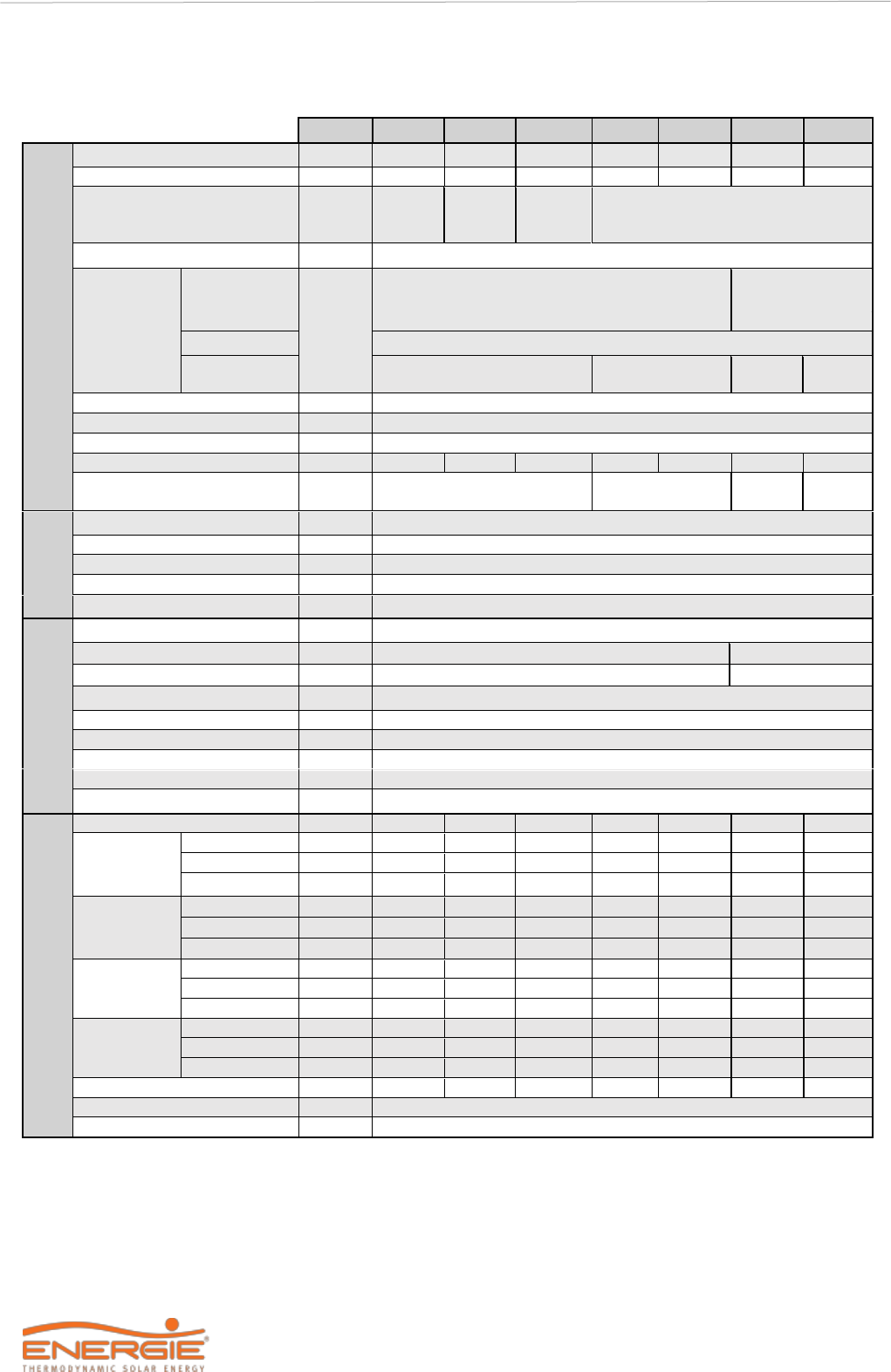
3.2 Techincal Features (1 panel)
Uni.
200i
250i / esm
300i / esm
250ix
300ix
HOT WATER CYLINDER
Dry Weight
kg
40
45 / 83
50 / 95
52
57
Capacity
L
200
250
300
245
295
Water Heater Material
-
Stainless
Steel
Stainless Steel /
Enamelled
Stainless Steel
Cathodic Protection
-
Magnesium Anode (1”1/4 F) (if applicable)
Hydraulic
Joints
Water – Inlet
and Outlet
Pol.
3/4” Male
PT Valve
1/2” Female
Recirculation
3/4” Male
Coil | Inlet e
Outlet
1” Male
Insulation
-
High density polyurethane 50mm
Maximum Pressure
bar
7
Maximum Pressure
°C
80
Heat Loss (EN 12897)
kWh/24h
0,99
1,01 / 1,20
1,17 / 1,39
1,01
1,17
Exchanger Output Power*
kW
-
a) 20 b) 12
SOLAR
PANEL
Material
-
Solar Coat Anodized Aluminium
Dimensions (L x A x E)
mm
2000 x 800 x 20
Weight
kg
8
Max Working Pressure
bar
12
Exposure Temperature
°C
-40 | 120
THERMODYNAMIC
BLOCK
Absorved Power (Med/Max)
W
390 | 650
Thermal Power (Med/Max)
W
1400 | 2380
Electrical Backup Power
W
1500
Refrigerant / Qt.**
- / g
R134a / 1300
Piping Material
-
Copper (DHP ISO1337)
Line (Liq. | Asp)
Pol.
1/4” | 3/8”
Power Supply***
V / Hz
220-240 / Single phase / 50 or 60
Fuse (Main | Electrical Heater)
A
10 | 10
Working Temperature
°C
-5 | 45
PERFORMANCE****
Tapping Porfile
-
L
XL
XL
XL
XL
Coefficient of
Performance
(COP)
Air 2ºC
-
2,8
2,9
2,9
2,9
2,9
Air 7ºC
-
3,1
3,2
3,3
3,2
3,3
Air 14ºC
-
3,6
3,8
3,7
3,8
3,7
Energy
Efficiency
ErP Class
Air 2ºC
-
A+
A
A
A
A
Air 7ºC
-
A+
A+
A+
A+
A+
Air 14ºC
-
A++
A+
A+
A+
A+
Energy
Efficiency
Air 2ºC
%
118
121
119
121
119
Air 7ºC
%
132
132
137
132
137
Air 14ºC
%
154
155
151
155
151
Annual
Energy
Consumption
Air 2ºC
KWh/ano
869
1389
1411
1389
1411
Air 7ºC
KWh/ano
774
1268
1227
1268
1227
Air 14ºC
KWh/ano
664
1078
1111
1078
1111
Mixed Water at 40°C
L
247
349
389
342
382
Default Setpoint
°C
53
Sound Power Level Indoor
dB
47
* a) Primary circuit (Tin =90 °C; Tout =80 °C); Production DHW (Tin=10 ºC; Tout=60 ºC)
b) Primary circuit (Tin =70 °C; Tout =60 °C); Production DHW (Tin=10 ºC; Tout=60 ºC)
** The amount of fluid must be checked by the installer. In some cases it is necessary to add or remove fluid in
order to ensure the correct running of the system.
*** The frequency of 60Hz is a version of the equipment produced only by specific request.
**** According to EN16147, Delegated Regulation (EU) Nº 812/2013 and Delegated Regulation (EU) Nº 844/2013,
for the three climatic zones: colder (20C), medium (70C) and warmer (140C).
Technical Manual
13
ECO
3.3 Techincal Features (2 panels)
Uni.
200is
250is
300is/esm
250isx
300isx
500is
500isx
HOT WATER CYLINDER
Dry Weight
kg
40
45
50/95
52
57
73
93
Capacity
L
200
250
300
245
295
455
443
Water Heater Material
-
Stainless
Steel
Stainless
Steel
Stainless
Steel /
Enamelled
Stainless Steel
Cathodic Protection
-
Magnesium Anode (1”1/4 F) (if applicable)
Hydraulic
Joints
Water – Inlet
and Outlet
Pol.
3/4” Male
1” Male
PT Valve
1/2” Female
1/2” Male
Recirculation
3/4” Male
Coil | Inlet e
Outlet
-
1” Male
-
1” Male
Insulation
-
High density polyurethane 50mm
Maximum Pressure
bar
7
Maximum Pressure
°C
80
Heat Loss (EN 12897)
kWh/24h
1,04
1,01
1,17/1,39
1,01
1,17
1,81
1,81
Exchanger Output Power*
kW
a) 20 b) 12
-
a)54,2
b)12
SOLAR
PANEL
Material
-
Solar Coat Anodized Aluminium
Dimensions (L x A x E)
mm
2000 x 800 x 20
Weight
kg
8
Max Working Pressure
bar
12
Exposure Temperature
°C
-40 | 120
THERMODYNAMIC
BLOCK
Absorved Power (Med/Max)
W
620 | 950
Thermal Power (Med/Max)
W
2300 | 3760
2300 | 4500
Electrical Backup Power
W
1500
2200
Refrigerant / Qt.**
- / g
R134a / 1300
Piping Material
-
Copper (DHP ISO1337)
Line (Liq. | Asp)
Pol.
3/8” | 1/2”
Power Supply***
V / Hz
220-240 / Single phase / 50 or 60
Fuse (Main | Electrical Heater)
A
10 | 10
Working Temperature
°C
-5 | 45
PERFORMANCE****
Tapping Porfile
-
L
XL
XL
XL
XL
XXL
XXL
Coefficient of
Performance
(COP)
Air 2ºC
-
2,76
2,8
2,8
2,8
2,8
2,9
2,9
Air 7ºC
-
3,09
3,2
3,1
3,2
3,1
3,3
3,3
Air 14ºC
-
3,55
3,7
3,7
3,7
3,7
3,5
3,5
Energy
Efficiency
ErP Class
Air 2ºC
-
A+
A
A
A
A
A
A
Air 7ºC
-
A+
A+
A+
A+
A+
A+
A+
Air 14ºC
-
A++
A+
A+
A+
A+
A+
A+
Energy
Efficiency
Air 2ºC
%
116
117
116
117
116
118
118
Air 7ºC
%
130
132
130
132
130
132
132
Air 14ºC
%
151
152
151
152
151
139
139
Annual
Energy
Consumption
Air 2ºC
KWh/ano
885
1438
1447
1438
1447
1823
1823
Air 7ºC
KWh/ano
786
1272
1300
1272
1300
1638
1638
Air 14ºC
KWh/ano
679
1103
1112
1103
1112
1553
1553
Mixed Water at 40°C
L
247
349
389
342
382
599
592
Default Setpoint
°C
53
Sound Power Level Indoor
dB
47
* a) Primary circuit (Tin =90 °C; Tout =80 °C); Production DHW (Tin=10 ºC; Tout=60 ºC)
b) Primary circuit (Tin =70 °C; Tout =60 °C); Production DHW (Tin=10 ºC; Tout=60 ºC)
** The amount of fluid must be checked by the installer. In some cases it is necessary to add or remove fluid in
order to ensure the correct running of the system.
*** The frequency of 60Hz is a version of the equipment produced only by specific request.
**** According to EN16147, Delegated Regulation (EU) Nº 812/2013 and Delegated Regulation (EU) Nº 844/2013, for the three
climatic zones: colder (20C), medium (70C) and warmer (140C).

Technical Manual
14
ECO
3.4 Main Components
3.4.1 General Diagram of Assembly
CAPTION
1
Shut Off Valve
7
Drain Valve
2
Pressure Reducing Valve (3 bar / 0,3 MPa)
8
Circulation Pump
3
Non-return Valve
9
Thermostatic Mixing Valve
4
Safety Group (7 bar / 0,7 MPa)
A
Cold Water Inlet
5
Drainage Siphon
B
Hot Water Outlet
6
Expansion Vessel
C
Recirculation
WARNING
It is necessary to install a safety device at the cold water inlet of the appliance.
The safety device must be in compliance with the standard EN 1487:2002,
maximum pressure 7 bar (0.7 MPa) Water must not be stopped from flowing
from the safety device to the deposit by any sort of accessory.
The safety device must be connected with piping whose diameter is not less
than the cold water inlet coupling. The discharge must be connected to a
sewage siphon or, if this is not possible, elevated to a distance of at least 20 mm
from the pavement to allow visual inspection;
To prevent high pressure from main water supply, install a pressure reduction
valve set to 3 bar (0.3 MPa).
1
2
3
1
5
6
7
1
8
3
1
9
B
C
A
4
Technical Manual
15
ECO
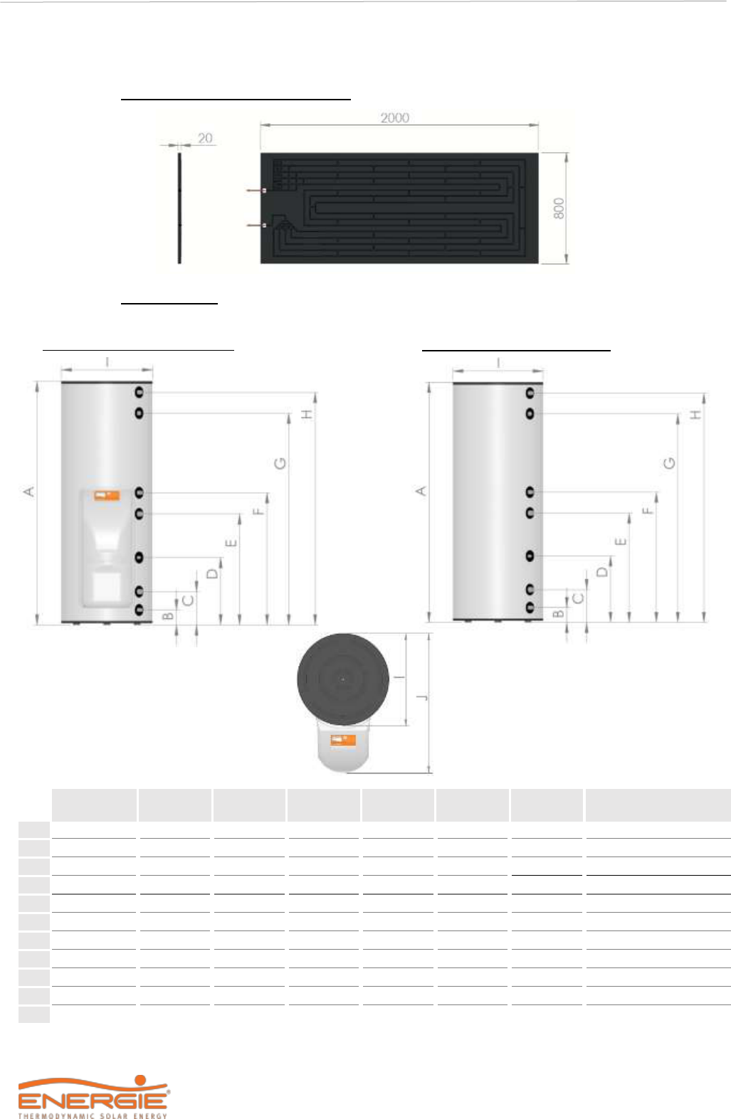
3.4.2 Dimensions
Thermodynamic Solar Panel
Interior Unit
Ø
200 i
250 esm
250 i/ix
300 esm
300 i/ix
500 i/ix
Obs.
Pol.
mm
mm
mm
mm
mm
mm
-
A
-
1240
1540
1540
1430
1400
2020
-
B
G ¾” M
131
99
131
102
107
102
Cold Water
C
G 1” M
-
-
231
-
236
635
Coil Outlet
D
-
-
-
435
-
436
-
Instrumentation
E
G 1” M
-
-
690
-
636
1525
Coil Inlet
F
G ½” F
-
840*
840
782*
855
782
Recirculation
-
G 1 ¼” M
-
1025
-
1096
-
1093
Magnesium Anode
G
G ½” F
905
1351
1205
1182
1065
1770
PT Valve
H
G ¾” M
1030
1477
1325
1325
1190
1937
Hot Water
I
-
Ø 580
Ø 580
Ø 580
Ø 650
Ø 650
Ø650
-
J
-
875
875
875
945
945
945
-
*G ¾” M
ECO 200I | ECO 250I/IX
Front hydraulic connections
ECO 250esm | 300esm/I/IX | ECO 500I/IX
Rear hydraulic connections

Technical Manual
16
ECO
3.4.3 ID Plate
Any contact with the installer or manufacturer must be accompanied by:
• Model;
• Serial number;
• Date of production.
The provision of these data will facilitate all communication and consequently a faster
and more correct response.

Technical Manual
17
ECO
3.4.4 Thermodynamic Solar Panel
The thermodynamic solar panel, responsible for the process of evaporation of the fluid, is made of
aluminium, with post-pressing anodic oxidation that gives it a black appearance.
There are two types of panels: left and right (designated by the connection side):
Left Panel Right Panel
The panels have the following pipe diameters:
•
3/8” aspiration (upper joint)
•
1/4" liquid (lower joint)
In the case of panel equipment, the refrigerant connections are of the conical threaded type (Flare
SAE):
For each panel, the elements supplied are:
1)
Thermodynamic Solar Panel;
2)
Aluminium L-shaped for attachment of Thermodynamic Solar Panel (6x ou 12x);
3)
Fixing elements.
ODS (welded on the
panel)
3/8” Flare Male SAE
ODS (welded on the
panel)
1/4” Flare Male SAE
1
2
3

Technical Manual
18
ECO
3.4.5 Thermodynamic Block + Storage Water Heater
Thermodynamic Block
We call the Thermodynamic Block to the components based on a galvanized steel structure, which
contains two of the main elements for the operation of the thermodynamic cycle: compressor and
expansion valve.
On the side of the block there are 2 and 3 way valves for connection to the panel (3/8 ’’ - Aspiration;
1/4 ’’ - Liquid).
This Thermodynamic Block is coupled to the water heater through three M8 screws and connected
to the condenser, which surrounds the water heater, through two One-Shot valves.
Storage Water Heater
The domestic hot water storage heater is vertical, resting on the ground. Thermal insulation is done
by means of high density polyurethane.
The water heater had:
• Cold water inlet;
• Hot water outlet;
• Recirculation;
• Pressure and temperature valve / instrumentation;
• Magnesium anode (joint 1 1/4" F) (if applicable);
• Possibility of integrating support coil (joint 1 "M);
• Electrical heater;
• Safety thermostat;
• Temperature probe.
Liquid Accumulator
Compressor
Electronic PCB
2-Way Valve –
Thermodynamic Panel
3-Way Valve – Thermodynamic Panel
One-Shot Valve Female
Thermostatic Expansion Valve
One-Shot Valve Male

Technical Manual
19
ECO
3.4.6 Refrigerant
R134a is an HFC refrigerant, and as such, it is not harmful to the ozone layer. They have great thermal
and chemical stability, low toxicity, are not flammable and are compatible with most materials. The
following table lists the evaporation temperature with the pressure:
T (ºC)
P (bar)
T (ºC)
P (bar)
-20
0,33
20
4,70
-15
0,64
25
5,63
-10
1,00
30
6,70
-5
1,43
35
7,83
0
1,92
40
9,10
5
2,49
45
10,54
10
3,13
50
12,11
15
3,90
55
13,83
3.5 Safety and Control Devices
3.5.1 Low Pressure Switch
In case of running outside the range of pressures recommended and defined by the supplier, the
equipment will switch off and indicate error in the electronic panel.
3.5.2 Safety Thermostat
The safety thermostat is set by the supplier to ensure that the water temperature in the storage water
heater does not exceed the standard value. If the temperature exceeds this value, the thermostat
switches off the backup electrical heater. Switching on is done manually by qualified staff, after
analysing the reasons for the switch off.
3.5.3 Temperature Probe
The purpose of the temperature probe is to measure the temperature values of water in the storage
water heater in order to control the system.
3.5.4 Protection Against Corrosion (if applicable)
Besides being resistant to corrosion (stainless steel), the storage water heater has in addition a
magnesium anode that should be checked periodically according to information by the installer.
3.5.5 Dielectric Joint (enamelled boilers)
If the boiler is made of enamelled steel, the equipment contains two dielectric bushings. These
bushings prevent electrons from exchanging between the water inlet and outlet tubes and the water
heater itself. In this way, another protection against corrosion is created, which could be verified
especially in these points.
Thus, the bushings (A) must be tightened on the inlet (B) and water outlet (B) connections of the tank,
before placing the respective tubing (C).
B
C
A

Technical Manual
20
ECO
3.5.6 Expansion Vessel*
The expansion vessel is a device whose purpose is to compensate for the increase in water volume
due to temperature rise.
3.5.7 Safety Group
The safety device allows the system to be protected against anomaly situations: cold water supply,
hot water flowing back, emptying of the storage water heater and high pressure. The valve is
calibrated to activate at 0.7 MPa).
To drain the water in the storage water heater, you should close the supply valve and open the
discharge valve.
The safety valve discharge pipe must be open into the atmosphere, because the valve may drip water
or even discharge water.
The safety valve must be opened regularly to remove impurities and check that it is not blocked. The
discharge pipe must be installed in a vertical position. The discharge pipe must be installed upright
away from a cold environment.
3.5.8 Pressure Reducing Valve
The pressure reducing valve must always be installed upstream from the safety device, and ready to
activate in situations when the pressure in the circuit exceeds 3 bar (0.3MPa). This valve comes with
a pressure gauge.
*Parts not supplied by the manufacturer. They must be installed by the installer.
WANRNING
DANGER
The placement of this device is a recommended procedure for the correct installation
of the equipment.
The installation of this device is the responsibility of the installer. The absence of
this device will void the warranty. As a general rule it is installed in the cold water
pipe.
WARNING
DANGER
The placement of this device is a mandatory procedure for the correct installation
of the equipment.
The installation of this device is the responsibility of the installer. As a general rule it
is installed in the cold water pipe.
WARNING
DANGER
The installation of the pressure reducing valve must take into account the correct
direction of the hydraulic flow.
The correct direction is represented by an arrow on the component itself.
Incorrect installation poses a danger to equipment and people.

Technical Manual
21
ECO
4 INSTALLATION
Assembly sequence:
a)
Thermodynamic solar panel fixing
b)
Placement of the cylinder + thermodynamic
block
c)
Refrigerant connections
d)
Hydraulic connections
e)
Electrical connections
f)
Nitrogen load
g)
Leak verification
h)
Vacuum
i)
Installation start-up
The unit is preloaded for a maximum connection length of up to 12
meters (horizontal) between the panel and the water heater.
Longer distances decrease the performance of your equipment.
4.1 Attachment of the Panel
The nature of the site and the inclination angle where the panels are installed are important factors to
take into account. In order to benefit the most from the sunlight exposure, the panels.
Should have a pitch between 10º and 85º relative to the horizontal plane, and preferably oriented to
the south.
The panel already comes with 6 holes for M8 in the lateral skirts. The distance between holes in the
place where the panel rests, should coincide with the holes made in the panel.
WARNING
DANGER
Attachment to at least 6 points (3 upper points and 3 lower points) is
mandatory!
The lack of at least one of these points can cause deformations in the panel and in
some cases the displacement of the panel from the installation site.
In very windy areas or climatic conditions conducive to bad weather, it is advisable to
fix the panels at more points.
Fixing the Aluminium Profiles: Fixing the aluminium profiles and the panel:
1
Aluminium profile
2
Plastic bushing
3
Self-tapping screw M6x40
4
Washer M6
5
Screw M6x20
6
Nut M6
7
Panel

Technical Manual
22
ECO
The system has 3 small profiles (side A) and 3 large profiles (side B) that must be fixed as shown in
the image, giving the panel a desirable inclination.
If the panel is to be installed in a climatic zone conducive to snowfall, the panel must
be installed with a minimum slope of 45º!
The profile must be fixed to the base (eg tile) using a plastic anchor and M6 screw provided. The
panel is fixed to the profiles using the M6 screws and the respective nuts and washers.
The panel packaging has a marking that can serve as a guide to guide the holes in the base.
This marking follows the following figure:
• A – Liquid inlet
• B – Vapour outlet (aspiration)
WARNING
DANGER
The panel must always be installed with the connections facing downwards.
750 mm
850 mm
850 mm
SIDE B
SIDE A

Technical Manual
23
ECO
4.2 Positioning
Preliminary considerations:
• House and protect the equipment in places susceptible to ice formation;
• Choose the position closest to the main points of use;
• Always insulate the pipes;
• The ambient temperature around the equipment must not exceed 40 ° C;
• The water heater should never be placed outside, also avoiding exposure to sunlight - failure
to respect this parameter can lead to the exclusion of the warranty;
• Make sure that the support surface is sufficient to accommodate the weight of the water-filled
water heater;
• Provide at least 500mm of space on the fronts that may require maintenance.
4.3 Installation of Thermodynamic Block
When assembling the thermodynamic block, must:
a) Tighten the three M8 bolts (A), in the storage water heater;
Do not fully tighten the screws, so that it is easy to insert the thermodynamic block,
giving the final tightening only after inserting the block in the water heater.
500mm
500mm
500mm
A

Technical Manual
24
ECO
b) Aim the metallic structure with the orifices to the three M8 bolts previously mentioned.
c) Set the structure, gently on the screws, adjusting the final tightening of the same;
4.4 Refrigerant Connections
Diameter of the Pipes
Nº panels
Vapour (aspiration)
Liquid (panel inlet)
-
Inches
Inches
1
3/8”
1/4"
2
1/2”
3/8”
WARNING
DANGER
• Refrigerant connections must be made by a qualified technician, with a
professional certificate of capabilities for the purpose.
• Refrigerant connections must be thermally insulated to prevent burns and to
ensure optimum system performance.
• The system has an R134a fluid preload.
4.4.1 Connections to the panel
1 Thermodynamic Panel
a) Prepare the copper pipe, removing the protective caps from the extremities.
b) Place the extremity of the pipe upside down, cut the appropriate size of pipe and sand the
rough edge.
c) Remove the females from the connections to the panel and place them on the side of the tube.
d) Flange the tube with the appropriate tool shaping a conic edge, taking care that there should
be no burrs or imperfections and the length of the walls must be uniform.

Technical Manual
25
ECO
e) Squeeze the female with your hand, taking a few turns.
It is recommended to use thread sealant, appropriate for the purpose!
The sealant must be placed between these two steps [e); f)].
If in doubt, consult the manufacturer.
f) Give the final tightening by applying a twisting pair of values as indicated in the table;
2 Thermodynamic Panels
a) Prepare the copper pipe, removing the protective caps from the extremities.
b) Place the extremity of the pipe upside down, cut the appropriate size of pipe and sand the
rough edge.
c) Then remove the covers from the panel connections and, using a sharp object, remove 5cm
of heat-shrink tubing from them;
d) Using the appropriate tool, must be made the tube expansion (3/8’’) suitable for connection
to the panel.
WARNING
Diameter of the pipe
(inches)
Applied Torque (Nm)
Wrench Nº
1/4”
14 to 16
19
3/8”
33 to 42
21
1.
2.
3.
5 cm

Technical Manual
26
ECO
e) Aim the liquid and suction tubes and before starting the welding operation, you must protect
the heat-shrink tubing (you can use a damp cloth);
f) After welding the panel connections and before installing the equipment, make sure the
apparatus has been cleaned with nitrogen.
For installations of two or more panels, it is essential that the refrigerant is distributed
evenly (Panel inlet). For this purpose, the equipment is already accompanied by a
liquid distributor.
Regarding the suction connections (Exit of the panels), the same symmetry accuracy
in the length of the tubes is not required. The same should be done by "chipping" or
with a "T" (as shown in the following image), properly isolated.
The type of solder recommended for welding the pipes is type oxyacetylene
(Oxygen/ Acetylene). Other types of gases can also be used, such as propane for
example.
WARNING
For installations of two or more panels, it is essential that the refrigerant is distributed
evenly (Panel inlet). For this purpose, the equipment is already accompanied by a
liquid distributor.
This distributor is placed between the two panels. The pipes connecting the
panels (1/4 ’’) must be exactly the same length, and their ends connect directly
to the panels.

Technical Manual
27
ECO
4.4.2 Connection of thermodynamic block to the storage water heater
After securing the thermodynamic block to the storage water heater with its bolts, we can proceed
with making the refrigeration couplings between the block and the storage water heater.
a) Remove the protection caps from the One-Shot valves on the pipes of the condenser and
thermodynamic block.
b) Tighten the valves with your hand making a few turns.
c) Tighten with a suitable wrench, applying a torque in conformity with the diameter of the pipe
employed (according to table in point 4.4.1). Insufficient torque will cause leaks of refrigerant.
Excessive torque on the coupling will damage the edge of the pipe and cause leaks.
4.4.3 Connection of thermodynamic block and panel
Some of the steps to be carried out are the repetition of the procedures carried out in
connection to the panel.
a) Cut the tube to the required size with the end facing down. Clean existing burrs;
b) Taper the tube, not forgetting to place the female on the side of the tube;
c) Squeeze the female with the hand, taking a few turns;
It is recommended to use thread sealant, appropriate for the purpose! The sealant
must be placed between these two steps [c); d)].
If in doubt, consult the manufacturer.

Technical Manual
28
ECO
d) Tighten with the appropriate wrench using the torque pair seen in the previous subchapter.
WARNING
It is important to keep the valves closed to proceed to the following points.
The water heater + thermodynamic group is filled with fluid.
The closed valves ensure that the fluid does not escape during the next steps.
All connections must be isolated!
1
3-Way-Valve
6
2-Way-Valve
2
Pressure intake
7
Conic nut
3
Valve socket
8
Liquid line (small diameter)
4
Valve needle
9
Gas line (large diameter)
5
Hexagonal tip wrench (Allen Key)

Technical Manual
29
ECO
4.4.4 Load of Nitrogen
a) After finishing the couplings, make sure there are no leaks. For this purpose, inject a load of
nitrogen with a pressure of 10 bar through the pressure inlet (3-way valve).
b) Brush every coupling in soap foam and make sure that the pressure in the pressure gauge is
constant.
4.4.5 Vacuum
a) During the whole procedure, employ, connections, vacuum pump and pressure gauges
suitable for fluid R134a.
b) Employ a vacuum pump only to remove the air and humidity inside the piping.
c) Never use the system coolant to purge the connection pipes.
d) The valves must be completely shut during the vacuum process, in order to create vacuum
only in the piping.
Closed Valves
A – 2-Way-Valves B – 3-Way-Valve
e) Create a vacuum with the vacuum pump plugged to the inlet of the 3-way pressure valve as
depicted, keeping the valves completely shut. The vacuum should be at least 30min for
installation of one panel and 45min for installation of two panels;
f) Once the vacuum procedure is over, shut the vacuum pump valves. The vacuum pressure
gauge should indicate the same reading after the pump has stopped, ensuring the installation
is in a vacuum and ready for running the coolant;
g) After concluding the vacuum procedure, you must open the two valves so that the coolant may
circulate throughout the whole system; the installation keeps the vacuum steady and is ready
for running the coolant;
h) Remove hose connected to 3-way valve.
Open Valves
A – 2-Way-Valve B – 3-Way_Valve
After vacuuming, do not remove the hoses until the system is fully pressurized by the
refrigerant.
This prevents atmospheric air (atmospheric pressure) from entering the system
(vacuum).

Technical Manual
30
ECO
4.4.6 Checking good running condition
To check whether your equipment is running correctly, start it and wait at least 30 minutes and then
check these conditions:
a) Super-heating, without solar radiation directly over the panel, should be within the range 5ºC
to 10ºC (Super-heating = Tsuction - Tevaporation);
b) The gradient between the gas temperature at the condenser inlet and the condensation
temperature must be within the range 16ºC to 20ºC.
4.4.7 Load of complementary refrigerant (if necessary)
Your unit has been pre-loaded for connections up to 12m (horizontal) between the panel and the
storage water heater. Longer distances will decrease the performance of your equipment.
Before carrying out an additional load of gas into the equipment, must prepare all the equipment and
tools necessary for the operation, such as:
• Gas bottles and their hoses
• Hexagonal-tip wrench to open the 3-way valve
• Scale with precision of 10 g
To carry out a complementary load of gas, follow these steps:
a) Place the cooling fluid tank on a scale with a 10 g precision and take note of the weight;
b) Connect the hose of the cooling fluid tank (R134a) to the inlet of the 3-way valve;
c) Switch off the compressor on the electronic panel;
d) Open carefully and only slightly the handle of the cooling fluid tank, notice the variation of the
figure indicated in the scale (as you load fluid into the circuit, the figure for the weight in the
scale will decrease);
e) When your reach the figure intended for the injection of cooling fluid into the circuit, close the
tank handle and remove the hose connected to the 3-way valve;
f) Switch on the compressor again and check how it runs.
4.5 Hydraulic Connections
WARNING/DANGER
The water you use may contain impurities and/or substances damaging to the system and even
harmful to your health. Make sure you use water with quality fitting for home consumption. The
following table indicates some parameters according to which water must be subjected to chemical
treatment.
Hardness (ºdH)
pH
Treatment
3,0 up to 20,0
6,5 up to 8,5
No
3,0 up to 20,0
<6,5 up to >8,5
Yes
<3,0 or >20,0
-
Yes

Technical Manual
31
ECO
To assemble the couplings of the hydraulic circuit you must:
a) Connect the water inlet and outlet of the equipment with a pipe and fittings that can cope with
constant temperature / pressure of 75 ºC / 7 bar. For this reason, we recommend the use of
piping with resistance to high temperature and pressure. We recommend the use of pipe type
PEX, PPR, MULTICAMADA, amongst others;
b) It is necessary to install a safety device at the cold water inlet of the appliance. The safety
device must be in compliance with the standard EN 1487:2002, maximum pressure 7 bar (0.7
MPa);
c) Besides this device, other components will be necessary to ensure the interruption of the
hydraulic load, installed according to this sequence:
• Retainer valve / gate valve
• Pressure throttle valve (in case the cold water inlet pressure exceeds 4.5 bar)
• Safety valve / discharge valve
• Expansion tank
The safety/discharge valve must be connected with piping whose diameter is not less than the cold
water inlet coupling. The discharge must be connected to a sewage siphon or, if this is not possible,
elevated to a distance of at least 20 mm from the pavement to allow visual inspection.
WARNING
We recommend the installation of a shut-off / section valve between the gate valve
and the coupling to the storage water heater for the purpose of maintenance, safety
or emergency.
The manufacturer is not responsible for damage related to not following these
recommendations / warnings.
4.6 Electrical Connections
To establish the electric connection of the equipment, check these conditions:
a) The thermodynamic equipment must be plugged to the power supply only after fill- ing the
storage water heater;
b) b) The thermodynamic equipment must be connected to a monophase voltage (230
VAC/50Hz or 60Hz* (version of the equipment produced only by specific request);
c) The connections must comply with the standards of installation in effect in the territory or
country where the thermodynamic equipment has been installed;
d) Earth wiring is obligatory.
It’s recommended that the installation includes:
• Bipolar circuit-breaker with connection cable with section equal to or exceeding 2.5 mm;
• Protection differential circuit breaker of 30 mA.
WARNING
The safety thermostat of this thermodynamic equipment must not, under any
circumstance, undergo any repair outside the installations of the manufacturer.
Not complying with this clause invalidates the warranty of the equipment.

Technical Manual
32
ECO
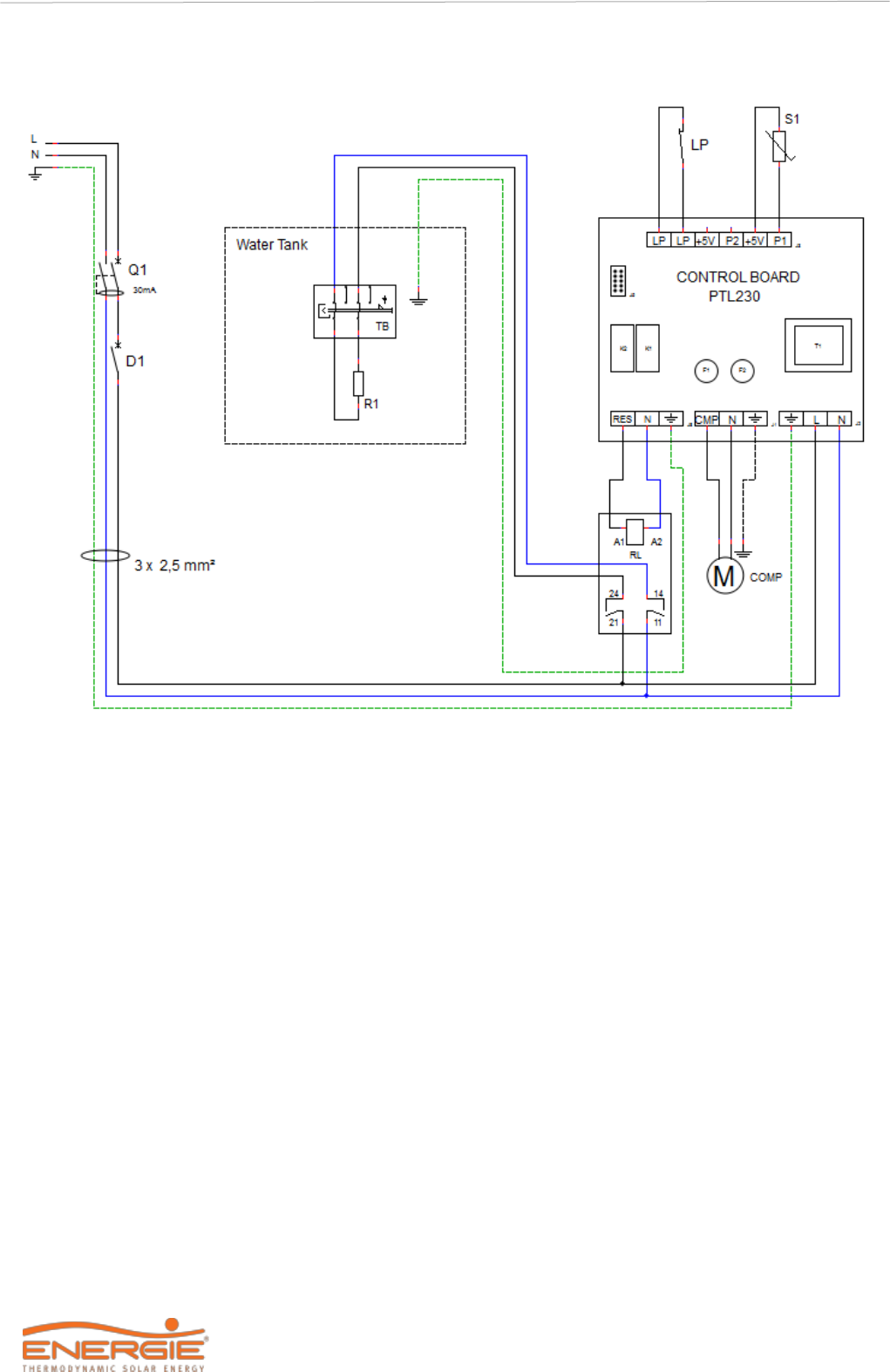
4.6.1 Wiring diagram (1 Thermodynamic Panel)
S1
Temperature probe
Comp
Compressor
LP
Low pressure switch
R1
Support electrical heater
D1
Circuit breaker
TB
Safety thermostat
Q1
Differential
Technical Manual
33
ECO
4.6.1 Wiring diagram (2 Thermodynamic Panels)
S1
Temperature probe
Comp
Compressor
LP
Low pressure switch
R1
Support electrical heater
D1
Circuit breaker
RL
Relay
Q1
Differential
TB
Safety thermostat

Technical Manual
34
ECO
5 FIRST USE
5.1 Filling the Tank
a) Open a cold water tap / isolation valve next to the safety group (this procedure is also used to
check if the drain valve is closed);
b) After obtaining flow in the hot water tap(s), shut it. Your water heater is full;
c) Check the tightening in the pipes;
d) Carry out successive discharges through the safety valve, in order to guarantee the proper
functioning of all hydraulic components of the installation.
5.2 Start Up of the System
Before starting the ECO, check whether the installation is set up according to the recommendations
and that everything is in conformity, then you may plug your equipment to the power supply. After
switching on your equipment, you should wait a few seconds until the controller begins to work.
Then you may start your equipment following these instructions:
1) Startup screen;
2) System is shut off. Press key ON/OFF to turn on the system;
3) Press the key COMP to start up the system;
4) System is running;
5) Setpoint has been reached.
Note 1: The LED on the ON / OFF button indicates the status of your device. If it is flashing, the
equipment does not have any operating order. If the light is on, your equipment is operating in one of
the available modes.
1
2
3
4
5

Technical Manual
35
ECO
6 SYSTEM OPERATION
6.1 Control Panel
The control panel of the Thermodynamic Solar system ECO is simple and intuitive. It enables the
configuration of several operating parameters according to the operating mode selected by the user.
It comprises six command keys that enable checking the running of the equipment, consult and
change parameters:
• ON / OFF / CANCEL;
• MENU;
• COMP;
• E-HEATER;
• DISINFECT;
• OK / LOCK.
6.2 Keys (Functions)
Key
Function
Description
ON/OFF
CANCEL
(ON/OFF) Switch
on/off
Switch on and off controller
(CANCEL ) Exit
ESC function to exit menu, submenu or cancel a function.
OK /
(OK) Confirmation
Confirm parameters within menus or submenus
(LOCK ) Lock/ Unlock
Lock or unlock keyboard
MENU
MENU
Access the menu.
COMP
ON/OFF Compressor
Switch on / off the Compressor.
E-HEATER
ON/OFF Electrical
Heater
Pressing the key allows you to switch on and off the
electrical heater
▲
▼
Change values
Function to run through menus and submenus (inside
Menu).
It allows you to alter value of parameter.
Browse
Menus/Submenus
DISINFECT
(DISINFECT) Anti-
legionella
Press this key and the system will automatically create a
thermal shock in the water to neutralize bacteria
(Legionella).

Technical Manual
36
ECO
6.3 Interface Symbols
Equipment in ECO operating mode
Equipment in AUTO operating mode
Equipment in BOOST operating mode
Compressor
Electrical heater
Unlocked keyboard
Locked keyboard
Timer activated after error of LP
Disinfect function is active
Holiday mode is active
Error alarm (visible on display during error)
Error memory (visible on display during 24h)
Water temperature scale in storage water heater
T
A
Electrical heater is activated when P02 < P08 and/or P07 < Temp.
S3 (Auto Mode)
T
C
Electrical heater is activated when time for continuous running of
Compressor is over T05 (Auto Mode)
LP
Electrical heater is activated by opening of LP contact (Auto/Boost
Mode)
M
Electrical heater is manually activated
6.4 Operating Modes
ECO
is programmed to work in 3 running modes,
ECO
,
AUTO
and
BOOST
, which are
summarized in this table:
The equipment is configured by default to work in the “
ECO
” operating mode. If the user
finds it necessary to change the operating mode, he must carry out the following procedures:
Unlock the keyboard and press the
Menu
key; on the ▲ ▼ keys, scroll through the menu
and select
F03
, access the submenu and select the desired operating mode
Modo
Simbologia
Funcionamento
ECO
Normal running as Thermodynamic System
AUTO
Optimized management of running of Thermodynamic System and/or
Electrical Heater (support)
BOOST
Running of Thermodynamic System + Electrical Heater (support)

Technical Manual
37
ECO
6.4.1 ECO Operating Mode
In ECO operating mode, the equipment runs only as a Heat Pump to heat the water in the storage
water heater. Thus, we could generate a greater efficiency, and savings for the user. Every time the
user feels it necessary, may switch on the support electrical heater, using this mode, manually
pressing the key (E-HEATER). In these circumstances the equipment will automatically change
operating mode to BOOST and indicates the reason of its activation (over the electrical heater). If you
switch off the electrical heater manually, the equipment will begin to run again in ECO mode.
6.4.2 AUTO Operating Mode
In AUTO operating mode, the equipment will run as a Thermodynamic System and/or electrical
heater, and the operation of the electrical heater is managed in an optimized way for the purpose of
keeping up the efficiency of the equipment.
The electrical heater will start every time:
• The user activates it manually (key E-Heater).
• The contact LP opens (low external temperature, lack of fluid, leak in the circuit, etc.).
• The time for running the compressor exceeds parameter T05*
• The water temperature is below P08*.
*Parameter is adjustable (ON / OFF)
6.4.3 BOOST Operating Mode
In BOOST operating mode, the equipment runs as a Heat Pump + Electrical Heater, and the
running of the electrical heater is simultaneous with the Heat Pump. This mode enables the user to
obtain hot water in less time.
The user can change the operating mode when he wishes, he need only press
simultaneously the keys MENU + OK/LOCK for 3 seconds and select the mode that
suits his needs with the cursor.
6.5 Extra Modes
6.5.1 DISINFECT Function
The
ECO
electronic controller is enabled with the
Disinfect
function, which consists of a
water heating cycle at 65 ° C, for an appropriate period of time to prevent the formation of
germs in the tank.
The
Disinfect
function can be configured automatically or manually. In automatic mode the
user has the possibility to configure the execution of the function daily, weekly or monthly,
being inactive the user has to activate it manually in the
Disinfect
button. At the end of the
function, the system returns to the operating mode initially adopted.
The Disinfect function is activated:
•
When pressed the disinfect button for 3 seconds;
•
On the penultimate day of the holiday period (during the holiday period the value
adopted in the disinfect parameter must be null);
•
Depending on the configuration adopted in the disinfect parameter;
•
The disinfect function is disactivated when the
CANCEL
or
COMP
key is pressed.

Technical Manual
38
ECO
6.5.2 VACATION Mode
To activate the
vacation
function, you need to access the menu and set the number of days
on holiday that you wish, and your equipment will automatically enter
Standby
mode until
the last day of holidays. On the last day, the equipment will begin the
Disinfect
function to
eliminate any formation of germs that appeared in the storage water heater during the time
you were absent. After the holidays and once the program Disinfect is over, the equipment
will resume the mode selected (
ECO
,
AUTO
or
BOOST
).
Note:
If you set your equipment to enter Vacation mode and turn it off with the key ON/OFF,
the function becomes inactive. When you return from your holidays you must remember to
switch on your equipment and cancel the days of holidays introduced (Value=0). If you do
not carry out this operation, your equipment will not restart until the days of holidays selected
have expired.
6.5.3 PV Mode
The PV function offers the possibility to raise the water temperature when an alternative electrical
energy source is available (solar photovoltaic, wind or other), increasing the efficiency of the heat
pump and making the alternative electrical energy source more profitable.
To do this, simply connect a cable from the inverter to the equipment control board. The cable
connection on the control board must be made at the 5V / P2 terminals. Note that this is a dry contact
(no voltage), applying a voltage to this contact can cause irreversible damage to the controller.
When the K1 contact closes, the PV function is activated and all active heat sources (Heat Pump +
Electrical Heater) are adjusted to new operating parameters. The compressor will assume the
parameters P01PV / H01PV and the electrical heaters the parameters P02PV / H02PV.
Note: when contact K1 opens, the equipment assumes the operating mode previously adopted.
Contact K1 can also be used to take advantage of bi-hourly rates. To do this, simply connect a timer
to the 5V / P2 terminals instead of the inverter.
OFF
ON
t
Set Point
Par (P01)
Par (P01PV)
Par (P02)
Par (P02PV)
Compressor
Resistência
K1
Electrical heater

Technical Manual
39
ECO
7 SYSTEM MENU
Every time it becomes necessary to change or set new parameters on the equipment, the user must
access the Menu.
To access the menu, the key MENU must be pressed for 3 seconds.
After access use the keys COMP
▲
and E-HEATER
▼
,to navigate the menus and submenus.
In order to confirm values/parameters press the key OK/LOCK. Press the key CANCEL to exit the
menu.
8 ERRORS
Symbols
Description
Problem
/
Checking
Er01 – S1
Anomaly
detected in probe
1
Damaged probe - Measure the probe's internal resistance
which at a temperature of 25ºC is approximately 10 KΩ.
Probe disconnected from the controller - Check that the
connector is securely connected to the electronic board
and/or that the connection terminals are tight.
Er02 – S2
Anomaly
detected
in probe 2,
when applicable
E03 – TA
Anomaly
detected in water
temperature
Water temperature in storage water heater is too hot –
Check that there is no anomaly in the electronic board, such
as a damaged relay.
Temperature probes in short-circuit – Measure internal
resistance of probe, it should be approximately 10 KΩ at the
temperature of 25ºC, check that the connector is well
attached to the electronic plate and the connection
terminals are in good condition.
Error “Lo”
Temperature
probe is
damaged or in
short-circuit
Check the connections of the temperature probe.
Replace with new probe.
LP
Protection
system is
activated
Check low pressure switch – Check if the connector is well
attached to the electronic plate and that the connection
terminals are secure, or that the pressure gauge is running.
Lack of refrigerant fluid in the circuit – Load of refrigerant
incomplete or leak. Low external temperature.
LINK
ERROR
Communication
failure
Connection cable between display and command panel
– Check the cable is in good condition or that the plugs are
correctly inserted (display and command panel).

Technical Manual
40
ECO
9 PARAMETERS DESCRIPTION
Values
Code
Type
Parameters
/
Description
Min
Max
Default
F01
Language
Português; English; Français; Deutsche; Español;
Italiano;
***
***
English
F02
Clock
Date and Time
***
***
***
F03
Mode
Eco
Boost
Auto
***
***
Eco
F04
Holidays
Number of days
0
366
0
F05
Disinfect
0- Disinfect function inactive
1- Disinfect function active once a week (weekly)
2- Disinfect function active once a month (monthly)
***
***
INACTIVE
F06
Parameters
P01 - Setpoint Compressor
1
10
55
52
0
C
H01 - Gradient P01
2
10
3
0
C
P02 - Setpoint Electrical Heater
1
65
52
0
C
H02 - Gradient P02
2
20
3
0
C
P05 – Safety Temperature
70
80
70
0
C
P06
- Setpoint Disinfect
60
69
65
0
C
P08 – Temp. min water to activate electrical heater
1
40
Value = 16 °C
Parameter=ON
T01 – Delay time to compressor starts running
1
20
2 min
T05 – Maximum time compressor running (AUTO)
6h
15h
Value = 12 horas
Parameter=ON
T07 – Delay time to compressor starts running after LP
error
2
20
10 min
P01PV - Setpoint Compressor (K1 contact closed)
10
55
55
0
C
H01PV –Gradient P01PV
2
10
3
0
C
P02PV - Setpoint Electrical Heater (K1 contact closed)
1
65
60
0
C
H02PV - Gradient P02PV
2
20
5
0
C
F07
Info
Information of the values configured in the parameter list.
F08
Levels of access
Installer
***
***
Password: 0022
F09
Test Outputs
CO – Contact N.O.
Compressor output active
OFF
ON
OFF
RE – Contact N.O.
Electrical heater output active
F10
Errors
Elist - Errors list
***
***
***
Ereset - Delete errors list
Manufacturer access
F11
Restore values
Restore all the parameters to factory values
***
***
***
F12
System
Probes’ configuration
Manufacturer access

Technical Manual
41
ECO
10 PROBE CHART
11 TROUBLESHOOTING
Problem
Possible causes
How to proceed
Failure in
electronic board
Power supply failure
Check the power supply
Check the corresponding circuit breaker
Cable damaged or disconnected
Check the integrity of the electronic board’s
electric circuit
Low water
temperature
Equipment is switched OFF
Press the key ON/OFF.
Absence of electrical current or damaged
wiring.
Check the connection of equipment to the
socket.
Check that the corresponding circuit-breaker is
connected.
Check the integrity of the cables. Check that the
electrical cable is disconnected from the
electronic.
Check electric protection (Fuse RES).
Component malfunction.
Check the presence of error on electronic board
and consult the table of errors.
Use of large amount of hot water
Set “BOOST” mode and wait for water heating.
Low temperature programmed in the
Setpoint.
Adjust the temperature of the Setpoint.
ECO mode is selected and outside
temperature quite low
Set “AUTO” mode to start automatic
management of system.
Set “BOOST” mode for a fast water heating.
Electrical heater is off.
Make sure electrical heater has power supply.
Compressor is off.
Switch on compressor with key “COMP”.
Return of hot water into the cold water
circuit (safety device incorrectly installed
or damaged)
Shut off the cold water supply valve to switch off
the safety device. Open a hot water tap. Wait 10
minutes and if you get hot water, replace the
faulty plumbing and/or proceed with the correct
positioning of the safety device.
Clean the filter of the safety device.

Technical Manual
42
ECO
Problem
Possible causes
How to proceed
Water is too hot
and/or there is
steam
Problem with the probe.
Problem with the thermostat.
Check error display on electronic board.
Check correct running of thermostat.
Slow running of
thermodynamic
solar system and
excessive
running of
electrical heater
(AUTO)
Outside temperature is very low
The running of the equipment depends
on weather conditions.
Inlet water temperature is very low
The running of the equipment depends
on the inlet water temperature.
Low value for Setpoint.
Increase the value of Set-point.
Installation has low electric voltage.
Make sure the installation is supplied
with the indicated value for voltage.
Problems with the thermodynamic solar
system.
Check the error display in the electronic board.
Low hot water
flow rate
Loss or clogging of hydraulic circuit.
Check the condition of the hydraulic circuit.
Loss of water
through safety
device
Absence or incorrect dimensioning
of expansion tank (if leak is not continuous)
Installation and/or correct dimensioning of
expansion tank.
Pressure in circuit is high (if the leak is
continuous)
Check the throttle valve (if there is one
installed).
Installation of a throttle valve (if it lacks one).
Consumption
abnormally high
and constant
electrical
Loss or obstruction in cooling circuit
Check that the piping is not damaged.
Employ equipment suitable for checking leaks
in the circuit.
Dire environmental conditions
Electrical heater
does not work
Thermostat failure
Check the condition of the thermostat.
Defective electrical heater
Check the condition of the electrical heater.
Bad odour
Absence of siphon or siphon without water
Install and make sure the siphon has water.
Others
Contact customer service.
12 SYSTEM MAINTENANCE
12.1 General Inspection
During the equipment’s useful life, the owner should carry out a general inspection of the
equipment, according to the place where the equipment is set up:
•
External cleaning of equipment and surrounding areas with a wet cloth;
•
Visual inspection of the whole equipment, with the purpose of detecting possible leaks
and damaged devices.
DANGER
Before carrying out any maintenance operations on the equipment, make
sure that it is not electrically powered!
Any intervention must be carried out by a specialized technician.

Technical Manual
43
ECO
12.2 Magnesium Anode (if applicable)
This equipment has a magnesium anode that together with the building material of the tank
will provide an
effective protection against corrosion.
The internal shielding of the tank will ensure an effective protection against corrosion
contributing to a water quality within the parameters considered normal. However, the
characteristics of the water change according to the installation. (See Chapter 4.5 and
warranty)
In your living area, the quality of the water can be aggressive to your equipment. So together
with the equipment there is a magnesium anode that wears over time, thus protecting your
equipment.
The wear of the anode always depends on the characteristics of the water you use. Thus,
checking the condition of the anode is very important, particularly in the first years of the
installation. To check the condition of your anode, follow these steps:
•
Unplug the appliance from the power supply
•
Shut off water supply
•
Remove pressure (for example, open a hot water tap)
•
Unscrew the anode with a suitable tool
•
Check the level of wear of the anode and replace it, if necessary
•
If the diameter of the anode is less than 15mm, it will need to be replaced
The extension of the deposit's anti-corrosion guarantee is conditioned to the sending
of documentary proof of the annual replacement of the magnesium anode.
12.3 Filter of Reduction Valve
To periodically clean the filter of the reduction valve, you should:
a) Shut off the water supply;
b) Turn anti-clockwise until you remove tension from the spring;
c) Remove the handle;
d) Remove filter and clean.
12.4 Safety Thermostat
The safety thermostat is disarmed whenever there is an anomaly in the system, so,
whenever you want to rearm it, find out what happened for it to have acted.
If you do not find out what happened and it is still disarmed, contact after-sales service to
have your case resolved.
If everything is in order and you want to reset the thermostat, proceed as follows:
Remove the bonnet by loosening the four screws present;
• Unscrew the cover (1);
• Press button (2) to reset the thermostat;
•
Retighten the cover (1) and replace the bonnet, tightening the four screws again.
1
2

Technical Manual
44
ECO
12.5 Empty the Water Storage
After ensuring the water temperature is at a safe level that will avoid burns, follow this
procedure:
•
Unplug the system from the power supply;
•
Shut off the water supply valve and open a hot water tap;
•
Open the system discharge valve.
13 DISPOSAL OF EQUIPMENT
The appliance contains refrigerant gas R134a, which should not be released into the
atmosphere. In case of permanent deactivation of the equipment, please contact a qualified
technician for the purpose.
The crossed-out wheelie bin symbol on the seal with features indicates that the product,
at its end-of-life, must be treated separately from household / urban waste. It must be
delivered to a separate collection centre for electrical / electronic equipment or returned
to the retailer at the time of purchasing new equipment. The end-user is responsible for
delivering the end-of-life device to an appropriate collection centre. Appropriate
differentiated delivery for recycling, treatment, and the environmentally compatible
disposal of the equipment helps to avoid possible harmful effects on the environment
and health, favouring the recycling of the materials that make up the product. For more
detailed information on the available collection systems, please contact your local waste
disposal service or the organization where you purchased the waste.
WARNING
Remember that the water in the storage water heater is at a high temperature,
so there is an associated risk of burns.
Before emptying the storage water heater, allow the water temperature to
drop to a level that avoids burns.

Warranty
This warranty covers all defects to the confirmed materials, excluding the payment of any type of personal
damage indemnity caused directly or indirectly by the materials.
The periods indicated below start from the purchase date of the apparatus, 6 months at the latest from the
leaving date from our storage warehouses.
Water Cylinder
(Domestic and Industrial)
5 Years: Stainless Steel (2+3 Years)*
5 Years Enamelled (2+3 Years)*
Manufacturer Warranty
Thermodynamic
Solar Panel
10 years against
corrosion
Electrical components and moving
parts:
• Thermodynamic Block
⚫ Solar Block
• Solarbox
⚫ Split
• Monobloc (except cylinder)
• Thermobox
• Inverter
2 Years
*The warranty extension of 3 years, against corrosion of the internal tank (Enamelled / Stainless Steel), is
conditioned to the submission of:
• Warranty and Check Sheet at maximum 15 days after the installation.
• Documental evidence of the magnesium anode annual replacement (if applicable).
• Pictures of the installation where it’s shown safety group, expansion vessel, hydraulic and electrical
connections.
In case of warranty, the parts replaced are property of the manufacturer. A repair under the warranty is not
reason for an extension of its term.
Warranty Exclusions
The warranty ceases to be effective when the apparatus is no longer connected, used or assembled in
accordance with manufacturer instructions, or if there has been any form of intervention by unauthorized
technicians, has the appearance of modifications and/or if the series number appears to have been removed or
erased. The equipment should be installed by qualified technicians according to the rules in effects and/or the
rules of the trade, or the instructions of our technical services. Further exclusions from warranty:
• Hot water tanks have been operating in water with the following indexes:
o Active chlorine > 0.2 ppm
o Chlorides > 50 mg/l (Inox)
o Hardness > 200 mg/l
o Conductibility > 600μS/cm (20ºC)
o PH < 5,5 or PH > 9 (Sorensen at 20ºC)
o Magnesium > 10 mg/l
o Calcium > 20 mg/l
o Sodium > 150 mg/l
o Iron > 1 mg/l
o If one of the water parameters has a higher value than stipulated by directive 236/98 (Portugal) or
equivalent standard in the costumer’s country
• Parts are subject to natural wear and tear – levers, switches, resistances, programmers, thermostats,
etc.
• Breakdown due to incorrect handling, electrical discharges, flooding, humidity or by improper use of the
apparatus.
• The warranty lapses if it is transferred to another owner, even if within the guarantee period.
• The warranty lapses if this certificate is incorrectly filled in, if it is violated or if it is returned after more
than 15 days have passed since the installation or purchase date of the apparatus.
NOTE: This sheet must be properly filled, signed and stamped by the installer / reseller and returned to
ENERGIE EST, Lda., otherwise the warranty will not be validated.
Send this installation sheet to [email protected], writing the serial number of the equipment as subject.

NOTES:

Technical Manual
3
ECO
