
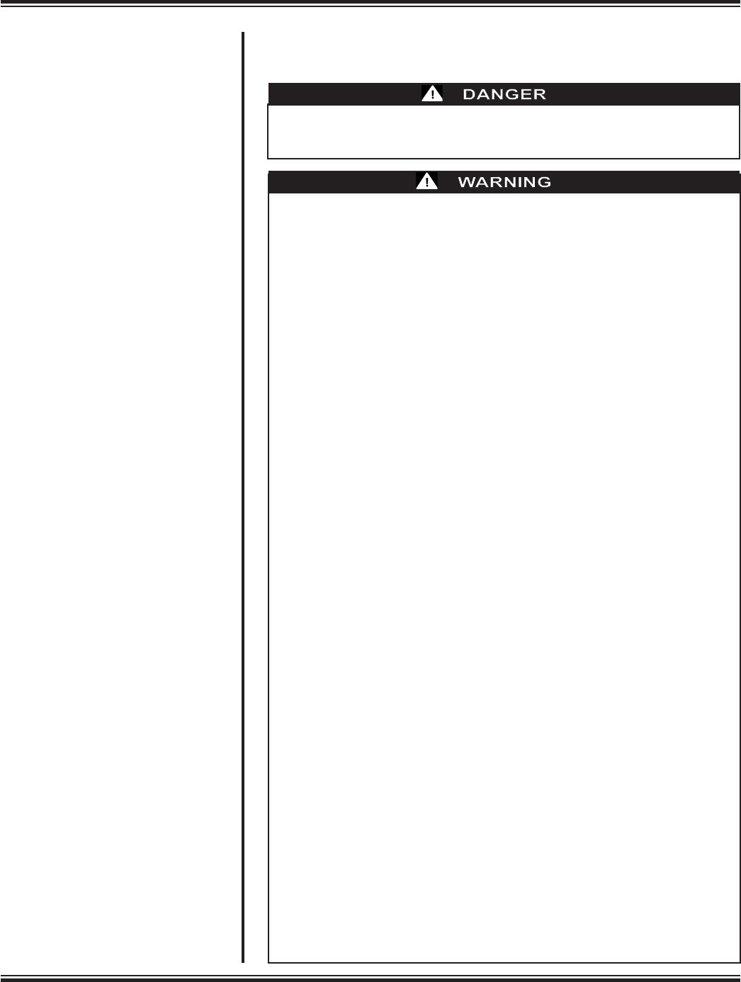
ALERT
To control temperature:WATER
To control temperature:PATIENT
•Connectbanket(s
)
•Inser t
p
atient
probe
•P ress button
Press
a
gaintos elect
Set desiredpatient
tempreature
AUTO
CONTROLOPTION
•
To monitor temperature:
•Insertpatientprobe
Press button
PATIENT
(NOTH ERAPY)
• MONITOR
SELECT MODE
SILENCE
ALARM
TEST LIGHTS
AND
A
LARM
CHECK W
A
TER FLOW.
CHECK
P
ATIENTP
ROBE.
ADDWATER
.
REMOVE
FROMUSE N
OW
.
MACHINES
HUTD
OWN.
MANUAL
AUTO
MONITOR
TEMPERA
TURE
Set
P
oint
W
ater
P
atient
°C/°F
War
ming
Cooling
Flow-OK
•Connectbanket(s)
•P ress button
Set desiredp atient
tempreature
MANUAL
•
MEDI-THERM
®
III
HYPER/HYPOTHERMIA MACHINE
MTA7900
SERVICE MANUAL
P/N 101251000 Rev A 04/10
www.gaymar.com

SERVICE MANUAL
Medi-Therm
®
III
SAFETY PRECAUTIONS
• Repairs should be performed only by qualied
personnel such as cert5ied biomedical
electronics technicians or certied clinical
engineers familiar with repair practices for
servicing medical devices and in accordance
with the Medi-Therm III Service manual.
• Always perform the FUNCTIONAL CHECK AND
SAFETY INSPECTION (section 7.3, p. 20) after
making repairs and before returning the Medi-
Therm
®
III machine to patient use.
Improper repair may result in death or
serious injury, equipment damage, or
malfunction.
Federal law restricts this device to sale by
or on the order of a physician.
RECEIVING INSPECTION
Upon receipt, unpack the Medi-Therm III machine. Save
all packing material. Perform a visual and mechanical
inspection for concealed damage by removing the
wraparound from the chassis (see page 75). If any damage
is found, notify the carrier at once and ask for a written
inspection. Photograph any damage and prepare a written
record. Failure to do this within 15 days may result in loss
of claim.
Refer to section 7.0 of this Medi-Therm III Service Manual
for additional details.
Do not return the Medi-Therm III machine to Gaymar
IndustrieswithoutrstcontactingGaymar’sTechnical
Service Department for assistance.
Telephone: Direct (716)662-2551
TollFree 1800828-7341
IMPORTANT
Before operating the Medi-Therm III machine, remove the
compressor shipping braces. See p. 88, gure B.
OPERATING INSTRUCTIONS
For more information on operating the Medi-Therm III machine,
refer to the Medi-Therm III Operator’s Manual.
Medi-Therm and Clik-Tite are registered trademarks of Gaymar Industries, Inc.
©2010. Gaymar Industries, Inc. All right reserved. www.gaymar.com

SERVICE MANUAL
Medi-Therm
®
III
i
CONTENTS
Section Description ................................................................................Page
1.0 PATIENTSAFETY ..................................................................... 1
2.0 MACHINEPRECAUTIONS ..................................................... 3
3.0 REPAIRPOLICY ........................................................................ 4
3.1 In-WarrantyRepairs ............................................................. 4
3.2 Out-of-WarrantyRepairs ..................................................... 4
4.0 SPECIFICATIONS ..................................................................... 5
4.1 PhysicalSpecications .......................................................... 5
4.2 ThermalSpecications ........................................................ 5
4.3 ElectricalSpecications ....................................................... 6
5.0 PROBEINFORMATION ........................................................... 7
6.0 THEORYOFOPERATIONS .................................................... 9
6.1 Machine.................................................................................. 9
6.2 Interconnections .................................................................. 11
6.3 PowerSupply ........................................................................ 12
6.4 MachineFunctions ............................................................... 12
7.0 FUNCTIONALCHECK,SAFETYINSPECTION,
PREVENTIVE MAINTENANCE ............................................. 18
7.1 ReceivingInspection ............................................................ 18
7.2 CleaningProcedures ........................................................... 18
7.3 FunctionalCheckandSafetyInspection ........................... 20
7.4 InspectionForm ................................................................... 33
8.0 TROUBLESHOOTING&SERVICEMODES ........................ 34
8.1 ServiceModes ...................................................................... 34
8.2 TroubleshootingCharts ...................................................... 38
9.0 REPAIR PROCEDURES ........................................................... 57
9.1 RefrigerationSystem .......................................................... 57
9.2 ReplacingthePowerSupplyBoard .................................... 59
9.3 ReplacingtheControl/DisplayBoard ................................ 60
9.4 ReplacingtheTopCover ..................................................... 61
9.5 ReplacingThermostats........................................................ 62
9.6 CleaningtheFlowSwitch ................................................... 63
9.7 ReplacementParts .............................................................. 64
9.8 Shipping/RepackingInstructions ........................................ 64
10.0 REFERENCETABLES ............................................................... 65
10.1 Celsius-FahrenheitConversion .......................................... 65
10.2 Temperaturevs.Resistance ................................................ 66
11.0 SERVICEINFORMATION ....................................................... 67
TABLES
Table Description ................................................................................Page
1 HighTemperatureLimits ......................................................... 25
2 RFUErrorCodes ...................................................................... 35
3 ServiceModes ........................................................................... 36
4 Celsius/FahrenheitConversion ................................................ 65
5 Temperaturevs.Resistance ..................................................... 66
6A OperatorControls/Indicators ................................................. 68
6B OperatorControls/Indicators ................................................. 71
7 PartsList(base) ........................................................................ 77
8 PartsList(head)........................................................................ 78
9 Control/DisplayBoardPartsList ............................................ 85
10 PowerSupplyBoardPartsList ................................................ 86
CONTENTS

SERVICE MANUAL
Medi-Therm
®
III
ii
ILLUSTRATIONS
Figure Description .............................................................................. Page
1 TypicalWaterWarm-upRate ................................................... 6
2 TypicalWaterCooldownRate ................................................. 6
3 Medi-ThermIIISystem ............................................................ 8
4 MT590TestTool........................................................................ 24
5 InitiatingServiceMode1 ........................................................ 35
6A/6L TroubleshootingCharts ........................................................... 38
6A AccessingRFUCodes ............................................................... 38
6B RFUCode1 ............................................................................... 39
6C RFUCodes2,3,–,E,andL ...................................................... 40
6D RFUCodes4,5 .......................................................................... 41
6E RFUCodes6,7 .......................................................................... 42
6F RFUCode8 ............................................................................... 43
6G RFUCode9 ............................................................................... 44
6H RFUCodeH(page1of2) ........................................................ 46
6H RFUCodeH(page2of2) ........................................................ 47
6I CheckWaterFlowAlertisOn(page1of2) .......................... 48
6I CheckWaterFlowAlertisOn(page2of2) .......................... 49
6J PumpMotorNotRunning ...................................................... 50
6K WaterWon’tHeatinAutoorManualMode(page1of2) ... 52
6K WaterWon’tHeatinAutoorManualMode(page2of2) ... 53
6L WaterWillNotCool(page1of3) .......................................... 54
6L WaterWillNotCool(page2of3) .......................................... 55
6L WaterWillNotCool(page3of3) .......................................... 56
7 FlowSwitch ............................................................................... 63
8 CircuitBoardsandConnectors(head)................................... 67
9A OperatorControls/Indicators ................................................. 68
9B OperatorControls/Indicators ................................................. 70
10 HeatingFlowDiagram ............................................................. 72
11 CoolingFlowDiagram ............................................................. 72
12 RefrigerationFlowDiagram .................................................... 73
13 TestSetup .................................................................................. 74
14 MachineDisassembly................................................................ 75
15 PartsDiagram(base) ............................................................... 76
16 PartsDiagram(head) ............................................................... 78
17 ThermostatWiringDiagram ................................................... 79
18 SystemWiringDiagram ........................................................... 81
19 PowerSupplyBoardSchematic(sheet1of3) ....................... 82
20 Control/DisplayBoardSchematic(sheet2of3) ................... 83
21 Control/DisplayBoardSchematic(sheet3of3) ................... 84
22 Control/DisplayBoard .............................................................. 85
23 PowerSupplyBoard ................................................................. 86
24 SystemBlockDiagram ............................................................. 87
25 Shipping/RepackagingInstructions ......................................... 88
FIGURES
SERVICE MANUAL
Medi-Therm
®
III
1
1.0 PATIENT SAFETY
Use the Medi-Therm III Hyper/Hypothermia machine only under the direction
of a physician.
Review the following precautions and procedures prior to each application:
• If the patient’s temperature is not responding or does not reach
the prescribed temperature in the prescribed time or deviates
from the prescribed temperature range, notify the attending
physician promptly. Failuretonotifythephysicianpromptly
mayresultindeathorseriousinjury.
• Power interruption will cause the Medi-Therm III machine to go
into a standby mode, resulting in no therapy to the patient. Follow
instructions for desired mode to resume operation. Failureto
resumetherapycouldresultindeathorseriousinjury.
• The Medi-Therm III machine is provided with a means of
checking rectal/esophageal temperature probes. When performing
the probe check, use a disposable protective sheath (Becton-
Dickinson catalog 3700 oral sheath or equivalent) on the probe.
Failuretousesheathcouldresultincross-contamination.
• When using the rate controlled Auto Moderate or Auto Gradual
modes for warming, switching to other modes, e.g. Auto Rapid or
Manual, or changing the temperature set point during the therapy
will cause the Medi-Therm to reset the therapy. Alternating
the Mode or Temperature set point may impact the
overalldurationofthetherapy.
• A physicians order is required for use of equipment. Check the
integrity of the skin according to department protocol when
regulating temperature with external devices. Frequency of
assessment and documentation will vary depending upon the
individual response of the patient. Failuretomonitorpatient
mayresultinskindamageorinappropriatepatient
temperature.
PEDIATRICS—The temperatures of infants and children are more
responsive to surface heating and cooling than adults. The smaller
the patient, the more pronounced the effect because of the
patient’s higher ratio of skin contact area to body mass.
TEMPERATURE-SENSITIVE PATIENTS—Patients with impaired
peripheral blood circulation caused by vascular diseases and
patients who are incapacitated may be more sensitive to
temperature changes than patients with more normal circulation.
OPERATING ROOM PATIENTS—Patients with poor circulation
associated with inadequate heart function, reduction in blood volume,
and constriction of peripheral blood vessels may deviate from the
normal response to the external application of heat and cold.
PATIENT SAFETY
Do not use the Medi-Therm III machine in the presence of
ammable anesthetics. Riskofexplosioncanresult.

SERVICE MANUAL
Medi-Therm
®
III
2
• Avoid placing additional heat sources between the patient and blanket/
body wrap. Skindamagecanresult.
Heat applied by the blanket/body wrap can result in a rise in skin
temperature at the areas of contact. The additional heat rise due to
electrosurgical currents owing to the dispersive electrode could
be sufcient to cause tissue injury. Each thermal effect by itself may
be completely safe, but the additive effect may be injurious.
1
Keep
additional heat sources from between the patient and the blanket/body
wrap.
• Prevent excessive and/or prolonged tissue pressure and shearing forces,
especially over boney prominences. Skindamagemayresult.
Localized skin injury due to tissue compressed between boney
prominences and uid-lled channels has occurred during prolonged
cardiovascular procedures at water temperatures well below the
scientically established epidermal burn injury threshold.
2
Local ischemia can follow the application of pressures exceeding
capillary pressure resulting in tissue necrosis. This local effect may be
enhanced by generalized impairment of the circulation, local shearing
forces and increased metabolic demand because of temperature eleva-
tion. Pathological changes may begin in two (2) hours.
• Keep the area between the patient and the blanket/body wrap dry.
Excessivemoisturemayresultinskindamage.
The application of heating or cooling may affect the toxicity of
solutions. Prep solutions have been reported to injure the skin when
allowed to remain between patients and water circulating heating
blankets/body wraps during prolonged procedures.
3
REFERENCES
1 Gendron, F. G. Unexplained Patient Burns. chap. 5, p. 87, Quest Publishing Co., 1988.
2 Scott, Stewart M. Thermal Blanket Injury in the Operating Room. Arch. Surg., vol. 94, p. 181, Feb. 1967; Crino, Marjanne H. Thermal Burns
Caused by Warming Blankets in the Operating Room. Clinical Workshop, vol. 29, pp. 149-150, Jan-Feb 1980; Gendron, Francis G. Journal
of Clinical Engineering, vol. 5, no. 1, pp. 19-26, January-March 1980; Moritz, A. R. and Henriques, Jr., F.C. Studies of Thermal Injury II. The
Relative Importance of Time and Surface Temperature in the Causation of Cutaneous Burns. Am. J. Path., 23:695, 1947; Stoll, Alice M. and
Chianta, Maria A. Method and Rating System for Evaluation of Thermal Protection. Aerospace Medicine, vol. 40, no. 11, pp. 1232-1238,
Nov. 1969; Stewart, T. P. and Magnano, S. Burns or Pressure Ulcers in the Surgical Patient. Decubitus, vol. 1, pp. 36-40, 1988.
3 Llorens, Alfred S. Reaction to povidone-iodine surgical scrub, scrub associated with radical pelvic operation. Am. J. Obstet. Gynecol., pp.
834-835, Nov. 14, 1974; Hodgkinson, Darryl J., Irons, George B. and Williams, Tiffany J., Chemical Burns and Skin Preparation Solutions.
Surgery, Gynecology & Obstetrics, vol. 17 pp. 534-536, Oct. 1978.
PATIENT SAFETY
1.0 PATIENT SAFETY
(continued)
• Place a dry absorbent sheet between the patient and the blanket
when using the plastic-like side of any blanket.
A dry absorbent sheet placed between the patient and the Hyper/
Hypothermia Blanket will absorb perspiration. Vinyl blankets and
body wraps with nonwoven fabric surfaces do not require an
absorbent sheet when using the nonwoven side toward the patient.
• Federallawrestrictsthisdevicetosalebyorontheorder
of a physician.

SERVICE MANUAL
Medi-Therm
®
III
3
MACHINE PRECAUTIONS
2.0 MACHINE
PRECAUTIONS
Disconnect power before servicing unit.Riskofelectricshock.
• Repairs should be performed only by qualied personnel such as certied biomedical
electronics technicians or certied clinical engineers familiar with repair practices for
servicing medical devices, and in accordance with the Medi-Therm III Service Manual.
Improperrepairmayresultindeathorseriousinjury,equipmentdamage,
ormalfunction.
• Always perform the FUNCTIONAL CHECK AND SAFETY INSPECTION (section 7.3, p.
20) after making repairs and before returning the Medi-Therm III machine to patient
use. Improperrepairmayresultindeathorseriousinjury,equipment
damage,ormalfunction.
• Some manufacturer’s patient probes may contain compensation resistors in series
with YSI 400 series thermistors. Do not use these probes with the Medi-Therm
III machine. Inaccuratepatienttemperaturereadoutswillresultand
inappropriatetherapymaybedelivered.
NOTE: Use only Gaymar probes or equivalent YSI 400 series probes approved for
use with medical devices.
(Refer to the list of recommended probes in section 5.0,
p. 7 PROBE INFORMATION.)
• All wire-lead, patient-connected transducer assemblies are subject to reading
error, local heating, and possible damage from high-intensity sources of RF energy.
Inadequately grounded electrosurgical equipment represents one such source, since
capacitively-coupled currents may seek alternate paths to ground through probe
cables and associated instruments. Patientburnsmayresult.
If possible, remove the probe from patient contact before activating the surgical unit or
other RF source. If probes must be used simultaneously with electrosurgical apparatus,
hazards can be reduced by selecting a temperature monitoring point which is remote
from the expected RF current path to the ground return pad.
• Do not tip machine over without rst draining the water out and unplugging the
power cord. Electricalshockordamagetothemachinecanresult.
Add distilled water only. Failuretousedistilledwatermayresultinpoormachine
performance.
• Do not use alcohol, since it is ammable. Alcohol may also accelerate blanket/body
wrap deterioration.
• Do not operate the machine without water, since damage to internal components
may result.
• Do not overll. Overlling may result in overow because the water in the blanket/
body wrap drains back into the machine when the machine is turned off. Overlling
may also result in splashing from the overow tube during transport.

SERVICE MANUAL
Medi-Therm
®
III
4
3.0 REPAIR POLICY
3.1 IN-WARRANTY
REPAIRS
3.2 OUT-OF-WARRANTY
REPAIRS
The Medi-Therm III Hyper/Hypothermia machine is warranted free of defects
in material and workmanship for a period of two (2) years, under the terms
and conditions of the Gaymar warranty in place at the time of purchase. The
compressor portion of the machine carries a ve (5) year prorated warranty.
The full warranty is available from Gaymar upon request. Medi-Therm III Hyper/
Hypothermia machines can be repaired at the factory or in the eld. Upon
customer request, a shipping carton will be provided to safely return the machine
to Gaymar or a qualied Service Center.
For customers who repair Gaymar Medi-Therm III machines at their location, this
manual contains information to allow a qualied biomedical technician, familiar
with practices for servicing medical devices, to make necessary repairs. Service
training for the Hyper/Hypothermia machine is recommended and is available
from Gaymar. For specic details, contact your Gaymar representative or the
Technical Service Department at Gaymar. (See back cover of this manual for
Gaymar telephone numbers.)
All in-warranty eld repairs must be authorized by Gaymar’s Technical Service
Department before proceeding.
The following repair options are available when local machine servicing is elected:
I . Defective Component
Replacement parts can be ordered. Specify the Gaymar part number; refer to
the Parts Lists in section 11, pp. 76–88 of this manual.
2. MachineRepairs
If the Medi-Therm III machine becomes defective and the cause of the
problem cannot be determined, the complete machine can be returned to the
factory for servicing at the purchaser’s expense. This normally represents the
most expensive repair option.
Please contact Gaymar to obtain an RG (returned goods) number prior
to returning the machine.
REPAIRS / WARRANTY

SERVICE MANUAL
Medi-Therm
®
III
5
4.1 PHYSICAL SPECIFICATIONS
SPECIFICATIONS
4.2 THERMAL SPECIFICATIONS
4.0 SPECIFICATIONS
MTA7900
Dimensions
37 in. high x 18-3/4 in. deep x 14 in. wide
(94.0 cm high x 47.6 cm deep x 35.6 cm wide)
Weight
141 lb (full); 121 lb (empty); shipping wt, 136 lb
64.0 kg (full); 54.9 kg (empty); shipping wt, 61.7 kg
Normal Reservoir Oper-
ating Volume
Approximately 10 quarts (9-1/2 liters) distilled water
Operating Ambient Tem-
perature Range
15.6ºC to 32.2ºC (60ºF to 90ºF)
Dead Head Pressure 9.0 psi max (62 kPa max)
Flow 16 gph (gallons per hour) 60.6 liters/hour) *
High Temperature Limits Fixed
(S2) & (S3)
44ºC (111.2ºF) to 49ºC (120.2ºF)
(Machine will go into REMOVE FROM USE NOW / MACHINE SHUTDOWN
condition and audible alarm will be on)
Low Temperature Limits Fixed (S1)
-3ºC (26.6ºF) to +2.5ºC (36.5ºF)
(Machine will go into REMOVE FROM USE NOW / MACHINE SHUTDOWN
condition and audible alarm will be on)
Add Water Alert Actuation Less than 8 quarts (7.6 liters) of water in the cold reservoir
Check Water Flow Alert Actuation 6 GPH
Check Probe Activation Tempera-
ture (whenever probe is used)
29ºC (84.2ºF) or above 45ºC (113ºF)
Patient Temperature Control
Range for Automatic Mode
30ºC (86.0ºF) to 41ºC (105.8ºF)
Water Temperature Control Range
for Manual Mode
4ºC (39.2ºF) to 42ºC (107.6ºF)
* Minimum ow rate through a full size Gaymar Hyper/Hypothermia Blanket

SERVICE MANUAL
Medi-Therm
®
III
6
4.2 THERMAL SPECIFICATIONS (cont'd)
4.3 ELECTRICAL SPECIFICATIONS
Figure 1—Typical water warm-up rate
(with full size blanket)
Figure 2—Typical water cooldown rate
(with full size blanket)
SPECIFICATIONS
MTA7900
Patient Temperature Measurement Accuracy
+0.5ºC, +0.9ºF
(using Gaymar 400 series probe)
Display Accuracy +0.3ºC, +0.5ºF
Display Resolution
Blanket Water Temperature 1ºC, 1ºF
Patient Temperature 0.1ºC, 0.1ºF
Controller Accuracy
Blanket Water Temperature
+0.8ºC, +1.4ºF
NOTE: At set points of 4ºC to 6ºC, this accuracy may not be
obtainable due to compressor control characteristics.
Patient Temperature +0.5ºC, +0.9ºF
Current Leakage
Chassis 100 microamps maximum
Patient Probe 50 microamps maximum
Input Voltage 120V + 10V
Frequency 60 Hz
Input Current 11.5A
Regulatory
UL416
CSA C22.2 No. 125
Electromagnetic Compatibility
Meets EN60601-1-2:1993
(CISPR 11 Classied as Class A,
Group 1 ISM Equipment)
Debrillation Proof
The Medi-Therm III MTA7900 along with its temperature probe
is a “Debrillator Proof, Type BF Applied Part” per IEC60601-1
standards.

SERVICE MANUAL
Medi-Therm
®
III
7
5.0 PROBE
INFORMATION
DisposableProbes
• DP400CE Disposable Rectal/Esophageal -
Adult/Small Child (3' [0.9 meters] long, requires adaptor);
YSI 400 series type
ProbeAdaptor
• ADP10CE Reusable adaptor cable for DP400CE: connects Gaymar
disposable probe to Gaymar or Cincinnati Sub-Zero
control unit.
ReusableProbes
• PAT101 Patient probe—Rectal/Esophageal -
Adult (10' [3.0 meters] long); YSI 400 series type
• PAT102 Patient probe—Rectal/Esophageal -
Pediatric (10' [3.0 meters] long); YSI 400 series type
• PAT108 Patient probe—Skin surface (10' [3.0 meters] long);
YSI 400 series type
PROBE INFORMATION
Some manufacturer’s patient probes may contain compensation resistors
in series with YSI 400 series thermistors. Do not use these probes with
the Medi-Therm III machine.
Inaccuratepatienttemperaturereadoutswillresultand
inappropriatetherapymaybedelivered.
NOTE: Use only Gaymar probes or equivalent YSI 400 series probes
approved for use with medical devices.
(Refer to the list of recommended probes above.)

SERVICE MANUAL
Medi-Therm
®
III
8
MEDI-THERM
®
III SYSTEM
Figure 3 - Medi-Therm III System
Hyper/Hypothermia
blanket/body wrap
Gaymar probe or equivalent YSI 400 series probe
approved for use with medical devices.

SERVICE MANUAL
Medi-Therm
®
III
9
The Gaymar Medi-Therm III machine provides a means of regulating patient
temperature by supplying temperature-controlled water through a connector
hose to a Gaymar Hyper/Hypothermia blanket/body wrap. The blanket/body wrap
provides an interface for heating or cooling the patient. A patient probe senses
patient temperature, which is displayed on the control panel. (See gure 3, p. 8.)
The Medi-Therm III machine controls output water temperature by mixing hot
and cold water using hot and cold solenoid valves under microcontroller control.
A circulating pump, heater and refrigeration unit are also utilized.
Bimetallic thermostats and associated backup circuitry limit output water
temperature independent of the microcontroller.
The feedback for control purposes depends upon the machine's operating mode.
The Medi-Therm III machine may be operated in one of three operating modes:
• In MANUAL mode, the operator sets the desired water temperature. A
temperature sensor within the machine monitors the water temperature
and the machine heats or cools the water as required to bring the water
temperature to the SET POINT temperature. The patient temperature may be
monitored by use of a patient probe connected to the patient probe jack on
the front of the unit.
• In AUTO mode, the Medi-Therm III machine automatically regulates the
patient's temperature to the selected SET POINT. The machine constantly
compares actual patient temperature with the SET POINT value, and
automatically adjusts the water temperature so that the desired patient
temperature is achieved.
• In MONITOR mode, the operator can monitor patient temperature through
the patient probe, without providing therapy.
Two gray hose sets are provided to connect multiple blankets and/or body wraps
in order to provide more body surface contact. Increased body surface contact
facilitates more efcient warming/cooling.
NOTE: When connecting a second blanket/body wrap to the Medi-Therm
III machine, check the water level prior to connecting the additional
blanket/body wrap.
Whenever the machine is on, 10 quarts of water are maintained cold in the cold
water reservoir. A cold water reservoir probe provides temperature feedback to
the microcontroller which cycles the refrigeration unit on at 5.8°C (42.5°F) and
off at 3.3°C (38.0°F).
When the water requires cooling, water is pumped from the cold water reservoir.
When the water requires heating, a cartridge heater is used to quickly heat the
water.
6.0 THEORY OF
OPERATION, SYSTEM
6.1 THEORY,
MEDI-THERM III
MACHINE

SERVICE MANUAL
Medi-Therm
®
III
10
WATER TEMPERATURE CONTROL
Hot and cold solenoid valves regulate the ow path by directing water
returning from the blanket/body wrap to either the hot or cold water reservoir.
Regulating the ow path controls the temperature of water pumped to the
blanket/body wrap. The microcontroller controls solenoid valve operation. Only
one valve may open at a time:
When the WARMING status light is lit, the hot solenoid valve is open.
Water returning from the blanket/body wrap circulates through the hot
water reservoir and is heated before being pumped back to the blanket/
body wrap. The heater, pump, and hot solenoid valve are energized. (See
g. 10, p. 72.)
When the COOLING status light is lit, the cold solenoid valve is open.
Water returns from the blanket/body wrap to the cold water reservoir
and is replenished by chilled water from the cold water reservoir
before being pumped back to the blanket/body wrap. The pump and
cold solenoid valve are energized. (See g. 11, p. 72.) The refrigeration
unit maintains the cold water reservoir temperature and operates
independently of the solenoid status.
When both the WARMING and COOLING lights are off, either the water
temperature is within 1°C (1.8°F) of the setpoint (in MANUAL mode) or the
patient temperature is within 0.5°C (0.9°F) of the setpoint (in AUTO mode).
Water temperature is controlled by alternating between heating and cooling (see
gures 10–11) with the heater cycled on and off as needed.
REFRIGERATION UNIT
The refrigeration circuit (see gure 12, p. 73) consists of two heat exchangers
operating at two pressures and two devices used to change these pressures. The
rst of these devices is the compressor which changes the gas pressure from
low to high. The other device is the capillary tube which reduces the refrigerant
pressure from high to low.
Beginning the cycle at the capillary tube, high pressure liquid refrigerant ows
in the capillary tube and is discharged into the evaporator coil. The evaporator
coil, which is a heat exchanger, receives the refrigerant as a mixture of liquid and
vapor at a pressure low enough so that it boils and absorbs heat from the water
surrounding it.
The heated refrigerant vapor then leaves the evaporator coils, enters the suction
side of the compressor and is compressed, causing its pressure and temperature
to increase. The vapor, much warmer than the ambient air, travels to the
condenser.
The condenser is the other heat exchanger. The condenser fan draws the colder
ambient air over the condenser coils and removes the heat being carried by the
refrigerant and causes it to condense back into liquid refrigerant. This completes
the cycle and the high pressure liquid refrigerant is returned to the capillary tube
to be used over again. The temperature of the water surrounding the evaporator
coil (in the cold water reservoir) is controlled by the microcontroller. The
microcontroller senses the temperature with a cold water reservoir probe and
cycles the compressor relay on and off.
6.1 THEORY OF
OPERATION,
MEDI-THERM III
MACHINE (continued)

SERVICE MANUAL
Medi-Therm
®
III
11
BACKUP SYSTEMS
Backup systems within the Medi-Therm III machine limit the temperature of
water exiting the machine to specied ranges in the event of a failure of the
control system including the microcontroller:
Maximumwatertemperature is limited by two bimetallic thermostats.
If either of these two thermostats is actuated, a REMOVE FROM USE NOW /
MACHINE SHUTDOWN circuit is triggered which:
• shuts down the pump and heater;
• lights the ALERT and the REMOVE FROM USE NOW / MACHINE
SHUTDOWN indicators; and,
• sounds the audible alarm.
In addition, if the microcontroller is operational, the compressor shuts down, the
displays blank, and the ALERT indicator and audible alarm turn on and off.
Minimum water temperature is limited by a bimetallic thermostat. If this
thermostat is actuated, a REMOVE FROM USE NOW / MACHINE SHUTDOWN
circuit is triggered, which in turn:
• shuts down the pump and heater;
• lights the ALERT and the REMOVE FROM USE NOW / MACHINE
SHUTDOWN indicators; and,
• sounds the audible alarm.
In addition, if the microcontroller is operational, the compressor shuts down,
the displays blank, and the ALERT indicator and audible alarm turn on and off.
See gure 8, p. 67 for base-to-head and control/display board-to-power supply
board connections; gure 18, p. 81 for system wiring diagram; gures 19–21,
pp. 82–84 for electrical schematics; gures 22–23, pp. 85–86 for component
layouts and part designations; and gure 24, p. 87 for the system block diagram.
CONTROL/DISPLAY BOARD AND POWER SUPPLY BOARD
The Medi-Therm III machine uses two printed circuit boards (see gure 8, p. 67):
• The control/display board contains the microcontroller circuits, the
display circuits, and all other low voltage control circuits.
• The power supply board contains the power supply, the low voltage
to high voltage interface circuits, and the REMOVE FROM USE NOW /
MACHINE SHUTDOWN backup safety circuits.
The control/display board connects to the patient probe jack J1 via P2 at J2 and
to the digital control assembly panel via P4 at J4. All other connections from the
system’s peripheral devices to the control/display board are made through the
power supply board.
A 26-pin cable connects the control/display board via P1 at J1 to the power supply
board via P3 at J4.
6.1 THEORY OF
OPERATION,
MEDI-THERM III
MACHINE (continued)
6.2 SYSTEM
COMPONENT
INTERCONNECTIONS

SERVICE MANUAL
Medi-Therm
®
III
12
Four cables connect the components in the base of the machine to the PC boards
in the head (see gure 8, p.67):
• A 9-pin connector P6 ties the water temperature probe RT2, cold
water reservoir probe RT1, ow switch S5, and level switch S4 to the
power supply board at J2 and ultimately to the control/display board.
• A 12-pinconnector P7 ties the high voltage devices (pump, heater,
hot solenoid valve SV2, cold solenoid valve SV1, and refrigeration
compressor relay K1) to the interface circuits on the power supply
board, as well as thermostats S1, S2, and S3 to the high voltage backup
circuitry on the power supply board.
• A 6-pinconnector P5 connects transformer T1 housed in the base
to the power supply circuitry at J3 on the power supply board.
• A chassisgroundharness from the control/display board connects
to the chassis.
See gure 18, p.81 for the system wiring diagram; gures 19–21, pp. 82–84 for the
electrical schematics; gures 22–23, pp. 85–86 for component layouts and part
designations; and gure 24, p. 87 for the system block diagram.
Power enters the Medi-Therm III machine through circuit breaker CB1 to feed
the refrigeration unit through relay K1. It also then enters the power supply board
at J1 to feed the hot solenoid valve, cold solenoid valve, heater and pump triacs,
the high voltage backup water temperature limiting circuits and transformer T1.
Power to drive the low voltage circuits on the control/display board is derived
from the machine’s power supplies which reside entirely on the power supply
board. The transformer T1 output is rectied and ltered to generate unregulated
positive and negative voltages. Q5, D1, L1 and associated components are
congured as a DC to DC switching regulator in a buck conguration yielding a
nominal output of +5.3 volts DC. Q6 is a linear regulator with a nominal output
of plus twelve (+12) volts DC, while Q7, also a linear regulator, delivers a nominal
output of minus twelve (-12) volts DC.
See gure 18, p. 81 for system wiring diagram; gures 19–21, pp. 82–84 for the
electrical schematics; gures 22–23, pp. 85–86 for component layouts and part
designations; and gure 24, p. 87 for the system block diagram.
The U37 microcontroller is fully dependent on the code stored in the U31
EPROM. When the machine is on, the microcontroller continually cycles through
its main program loop to perform the following:
• Thermistor output measurement (see section 6.4.1, p. 13)
• Digital control panel input (section 6.4.2, p. 13)
• Display update (section 6.4.3, p. 13)
• Peripheral input (section 6.4.4, p. 14)
• Water/Patient temperature control (section 6.4.5, p. 15)
• Cold water reservoir temperature control (section 6.4.6, p. 16)
Backup water temperature limiting is achieved independently of the
microcontroller. (See section 6.4.7, p. 16.)
6.2 SYSTEM
COMPONENT
INTERCONNECTIONS
(continued)
6.3 POWER SUPPLY
6.4 MACHINE
FUNCTIONS

SERVICE MANUAL
Medi-Therm
®
III
13
Temperature measurement is achieved using 400 series thermistor beads located
in the water path (water temperature probe RT2), the cold water reservoir (cold
water reservoir probe RT1), and in the patient via the patient probe jack J1.
Under microcontroller U37 control, each of the three beads is connected to the
current source circuitry (U38 and associated components) by a demultiplexor
U49. At the same time, the resulting output voltage created by the current
through the thermistor is presented to an amplier circuit (U39 and associated
components) via multiplexor U50. The amplied voltage is then applied to a
voltage-to-frequency converter U24. A frequency up to 100kHz is presented to
port pin P3.5 of the microcontroller. The microcontroller converts the incoming
frequency to a temperature value.
At regular intervals two compensation resistors R13 and R12 are also processed
in the same manner. These compensation resistors are precision resistors with
values at each end of the probe temperature range of 0°C (32°F) to 50°C (122°F).
The values from the precision resistors are used to compensate for circuit drift.
User input is entered via a digital control panel. The input from the buttons is
decoded by U45. The “data available” line of U45 is tied to the microcontroller
port pin P3.3. When a button press is decoded and debounced by U45, the
“data available” line goes high and the microcontroller responds by inputting the
decoded value.
For display of measured and set point temperatures, 7 segment LED displays are
utilized:
• The set point display is driven by driver chip U48. The microcontroller
interfaces to it via the data bus at addresses 0FFF8H, 0FFF9H, 0FFFAH,
0FFFBH.
• The patient display is driven by driver chip U6. The microcontroller
interfaces to it via the data bus at addresses 0FFF4H, 0FFF5H, 0FFF6H,
0FFF7H.
• The water temperature display is driven by driver chip U5. The
microcontroller interfaces to it via the data bus at addresses 0FFECH,
0FFEDH, 0FFEEH, 0FFEFH.
6.4.1 THERMISTOR
OUTPUT
MEASUREMENT
6.4.2 DIGITAL CONTROL
PANEL INPUT
6.4.3 DISPLAY UPDATE

SERVICE MANUAL
Medi-Therm
®
III
14
All alarm and status indicators are lit by LED bars driven by inverter/driver IC’s:
• The alarm latch U53 is the interface between the microcontroller
and the ALERT, ADD WATER, CHECK PROBE, CHECK FLOW, REMOVE
FROM USE NOW / MACHINE SHUTDOWN, SELECT, °F and °C drivers
via the data bus at address 0FFBFH. A high signal written to the latch
by the microcontroller activates the individual inverter/drivers to
light the corresponding indicator.
• The mode display latch U54 is the interface between the
microcontroller and the COOLING, WARMING, FLOW-OK, AUTO,
MANUAL, and MONITOR drivers via the data bus at address 0FFDFH.
A high signal written to the latch by the microcontroller activates
the individual inverter/drivers.
• The control option display latch U64 is the interface between the
microcontroller and the GRADUAL, MODERATE, and RAPID drivers via
the databus at address FDFFH. A high signal written to the latch by
the microcontroller activates the individual drivers.
• The control latch U51 is the interface between the microcontroller
and the two leader light drivers via the data bus at address 0FF7FH.
When this latch is selected, a low signal on the data line from the
microcontroller causes a high signal on the latch output Therefore,
these two LED bar displays are “active low” in the eyes of the
microcontroller in contrast to all the other LED bar displays of the
machine.
The audible alarm is driven either by a high signal from the control latch U51
(from the microcontroller via the data bus at address 0FF7FH) or a high RFU
IN signal from Q10 on the power supply board. A low data line signal from the
microcontroller to U51 causes a high signal on the latch output. Therefore, the
alarm is “active low” in the eyes of the microcontroller. Transistor Q2 activates
the alarm.
The input buffer U55 is the interface between the microcontroller (via the data
bus at a “read” address of 0FFFEH) and the input signals from the ow switch S5
and the level switch S4 (which travel from the base through the power supply
board), the probe presence switch within the patient probe jack J1, and the
service mode button S3 on the control/display board. The lines to the buffer from
the peripheral devices are default high (via pull-up resistors).
The level switch S4 will pull its buffer input line low when it senses a sufcient
water level.
The ow switch S5 will pull its buffer input line low when it senses sufcient ow.
The probe presence switch within J1 will pull its buffer input line low when it
senses the presence of the patient probe.
Pressing the service mode switch S3 on the control/display board will pull its
buffer input line low.
6.4.3 DISPLAY UPDATE
(continued)
6.4.4 PERIPHERAL INPUT

SERVICE MANUAL
Medi-Therm
®
III
15
If the machine is in MANUAL mode, the water temperature as sensed by the
water temperature probe is used as the feedback signal for controlling the water
temperature to the MANUAL mode set point temperature.
If the machine is in AUTO mode, the patient temperature as sensed by the patient
probe connected to the patient probe jack is used as the feedback signal for
controlling the patient temperature to the AUTO mode set point temperature.
The machine accomplishes this by adjusting the water temperature. The water
temperature the machine uses in AUTO mode is dependent on the CONTROL
OPTION setting selected and if COOLING or WARMING is desired.
When COOLING the patient:
RAPID - the coldest water is used for cooling - as low as 4°C (39°F). This may
not be the most comfortable setting for the patient.
MODERATE - Water temperature is limited to 15°C (27°F) below the patient's
temperature. This will provide an improved comfort setting to the patient.
GRADUAL - Water temperature is limited to 10°C (18°F) below the patient's
temperature. This will provide the optimal comfort setting to the patient.
When WARMING the patient:
RAPID - the highest allowable water temperature is used for warming - as
high as 42°C (107.6°F). This is the fastest warming mode the machine can
provide.
MODERATE - The patient temperature will increase at a rate of 1°C (1.8°F)
in a period of 3 hours (0.33°C/Hr [0.6°F/Hr]).
GRADUAL - The patient temperature will increase at a rate of 1°C (1.8°F) in
a period of 6 hours (0.17°C/Hr [0.3°F/Hr]).
When using AUTO MODERATE and AUTO GRADUAL for patient warming,
NO MANUAL INTERVENTION is required once the patient set point
temperature has been selected for warming.
When WARMING a patient in MODERATE or GRADUAL modes, water
temperature is limited to a maximum of 42.0°C (107.6°F) and a minimum which
is determined by the current control option selected 15.0°C [27°F] below the
patient temperature in MODERATE mode and 10.0°C [18°F] below the patient
temperature in GRADUAL mode).
If the patient temperature deviates from the warming rate specied by the
CONTROL OPTION selected (Moderate and Gradual only) by 1.0°C (1.8°F) the
following will occur:
• the PATIENT temperature will ash;
• the ALERT led will ash; and;
• the audible alarm will toggle
Once the patient temperature returns to within 1.0°C (1.8°F) of the warming
rate specied by the CONTROL OPTION selected, the PATIENT temperature and
ALERT light will stop ashing and the audible will silence.
NOTE: If the control MODE or SET POINT is changed while this alarm is
occuring, the alarm will be reset.
NOTE: If the control MODE or SET POINT is changed while in Auto-Gradual
or Auto-Moderate control mode, this may impact the overall time period
of the therapy depending on when in the hourly cycle the mode is inter
rupted. The therapy time duration is also dependent on the patient’s
temperature at the time the Auto-Moderate or Auto-Gradual control
modes are re-selected.
For water temperature control, the microcontroller outputs a pulse train to
each solenoid valve and the heater. The pulse train duty cycle depends on the
magnitude and sense of the control signal calculated by the microcontroller.
6.4.5 WATER / PATIENT
TEMPERATURE
CONTROL

SERVICE MANUAL
Medi-Therm
®
III
16
Pin 11 of U51 on the control/display board and U8 and Q9 of the power supply
board control the cold solenoid valve while pin 9 of U51 on the control/display
board and U7 and Q8 of the power supply board control the hot solenoid valve.
Pin 8 of U51 on the control/display board and U2 and Q4 of the power supply
board control the circulating pump. Pin 7 of U51 on the control/display board and
U1 and Q3 of the power supply board control power to the heater.
The control latch U51 on the control/display board is the interface between
the microcontroller (via the data bus at address 0FF7FH) and the refrigeration
compressor relay driver on the power supply board. A high signal on the
appropriate data line causes a low signal at pin 6 of U51 on the control/display
board, which then activates Q12 on the power supply board. Q12 on the power
supply board is the interface between the control/display board and the coil of
the power relay K1 located in the machine base. The microcontroller switches
power through the relay to the refrigeration compressor at cut-out and cut-in
temperatures of 3.3°C (38°F) and 5.8°C (42.5°F). These temperatures are sensed
by the cold water reservoir probe RTl located in the water reservoir. (See gure
12, p. 73.) Control of the cold water reservoir temperature takes place whenever
the machine is on.
The power supply board includes the REMOVE FROM USE NOW / MACHINE
SHUTDOWN circuitry, which includes U3, U4, U5, U6, U9, U10, D2, D3, Q1, Q2,
their interconnected components, and xed, nonadjustable thermostats S2, S3,
and S1 located in the base. Under normal circumstances, Q1 and Q2 are kept
turned on by the action of R7, C10, and D4 and R5, C15, and D5 to complete
the conduction path for the heater and pump. If the water temperature falls into
the low temperature limit range, S1 will open. If the water temperature rises
into the high temperature limits ranges, S2 and/or S3 will open. (See section 4.2
Thermal Specication table, page 5, for the correct high or low temperature limits
6.4.6 COLD WATER
RESERVOIR
TEMPERATURE
CONTROL
6.4.7 BACK-UP WATER
TEMPERATURE
LIMITING
That is, while the solenoids and heater are either on or off, the ratio of on time
to off time is proportional to the calculated control signal amplitude. For large
differences between set point and probe temperatures, the output to the cold
solenoid will be on and the output to the hot solenoid/heater combination will be
off, or vice-versa. For differences approaching zero, the output pulse train will be
applied to the hot solenoid and cold solenoid in a complementary fashion, with
the on times and off times automatically adjusted to maintain a probe temperature
equal to the set point, or the output pulse train will be applied to the heater (with
the hot solenoid remaining open), with the on times and off times of the heater
automatically adjusted to maintain a probe temperature equal to the set point.
The circulating pump is energized whenever the unit is in AUTO or
MANUAL modes.
The control latch U51 on the control/display board is the interface between the
microcontroller (via the data bus at address 0FF7FH) and the peripheral drivers on
the power supply board.
Interface circuitry on the power supply board consists of U1, U2, U7, U8, Q3, Q4,
Q8, Q9, and associated components. U1, U2, U7, and U8 are optically coupled
triac drivers used to control their respective triacs (Q3, Q4, Q8, and Q9); these
combinations provide electrical isolation between the low voltage microcontroller
control circuits and the line voltage circuits.
The heater, pump, hot solenoid valve, and cold solenoid valve are individually
controlled by the microcontroller through latch U51 on the control/display board.
A high signal on the data line from the microcontroller causes a low signal on the
appropriate output line of U51 which then sinks current from the power supply
board to activate the peripheral devices.

SERVICE MANUAL
Medi-Therm
®
III
17
6.4.7 BACK-UP WATER
TEMPERATURE
LIMITING (continued)
* RFU = REMOVE FROM USE NOW / MACHINE SHUTDOWN
THEORY OF OPERATION
with corresponding model number of your machine.) When any one of these
thermostats opens, it directly interrupts the circuit and shuts off the pump and
heater; at the same time, full line voltage will appear between J1-2 and J1-3. In this
case, U5 and U10 will be turned on by the action of R4, D3, and associated parts
while U3 and U9 will be turned on by the action of R6, D2, and associated parts.
U5 prevents Q2 from turning on and U3 prevents Q1 from turning on even if the
open thermostat(s) closes again. The output of either U9 or U10, through buffer
Q10, signals the microcontroller that a thermostat has tripped and that a REMOVE
FROM USE NOW / MACHINE SHUTDOWN condition has resulted. Thus, should
any thermostat (S1, S2, or S3) trip, the heater and pump are shut off and the
microcontroller is notied.
On the control/display board, a high signal from Q10 of the power supply board
feeds Q2 to drive the audible alarm, feeds driver U62 to light the REMOVE FROM
USE NOW / MACHINE SHUTDOWN LED, and feeds driver U60 to light the ALERT
LED. All this is done independent of the microcontroller. This same signal is sent
to port pin P3.2 of the microcontroller Q3.
If the microcontroller is operational at the event of a high signal from Q10 of the
power supply board, the signal at P3.2 causes the microcontroller to shut off the
7 segment displays, ash the ALERT LED and light the REMOVE FROM USE NOW /
MACHINE SHUTDOWN LED, toggle the audible alarm, store the appropriate RFU*
code indicating the reason for the shutdown, turn off the heater and pump triacs
Q3 and Q4, turn off the solenoid triacs Q8 and Q9, and turn off the compressor
transistor Q12. Anytime the microcontroller goes into a shutdown condition it
also sends an output signal from port pin P3.4, through U40 of the control/display
board, to command, via Q11, U4, and U6 on the power supply board, a REMOVE
FROM USE NOW / MACHINE SHUTDOWN condition. The process of turning
off the heater and pump triacs Q3 and Q4 by the microcontroller removes
power from the REMOVE FROM USE NOW / MACHINE SHUTDOWN circuitry
on the power supply board which then allows the indicators on the control/
display board to toggle under microcontroller control. This shutdown condition
by the microcontroller program will remain until the machine is powered down.
If, upon machine turn on, the fault condition still exists, attempting to resume
therapy (which would turn on the pump and possibly heater) will replace power
to the REMOVE FROM USE NOW / MACHINE SHUTDOWN circuits on the power
supply board and cause the REMOVE FROM USE NOW / MACHINE SHUTDOWN
condition to recur.
Also, if during normal operation, the microcontroller senses internal problems, it
will attempt a shutdown as described above. (See table 2, section 8.1, p. 35.)
If the microcontroller is nonoperational at the event of a signal from Q10 of
the power supply board, the user is notied of the REMOVE FROM USE NOW /
MACHINE SHUTDOWN condition by the fact that the above mentioned indicators
are on continuously. In addition, there are separate, redundant circuits on the
power supply board, each triggered by any of the thermostats, that insure that
the pump and heater remain off even if the thermostat cools sufciently to close
again. The REMOVE FROM USE NOW / MACHINE SHUTDOWN condition remains
latched and can be cleared only by an operator intervention in the form of turning
the machine circuit breaker off. If, upon machine turn on, the fault condition still
exists, attempting to resume therapy will cause the REMOVE FROM USE NOW /
MACHINE SHUTDOWN condition to recur.

SERVICE MANUAL
Medi-Therm
®
III
18
Concealed Damage
After unpacking the Medi-Therm III machine, inspect the machine for concealed
damage. Save all packing material and carefully describe or photograph the
damage. Notify the carrier at once and ask for an inspection (in writing). Failure
to do this within 15 days may result in loss of claim. Do not return the machine to
GAYMAR — call Gaymar's Technical Service Department for advice.
Before placing the Medi-Therm III machine into service, perform a FUNCTIONAL
CHECK AND SAFETY INSPECTION (pp. 20 to 33).
IMPORTANT
BeforeoperatingtheMedi-ThermIIImachine,removethe
compressorshippingbraces.(Seep.88,gureB.)
Fluid System
Use distilled water to retard algae growth and mineral buildup. Change the
distilled water monthly or more often depending upon use.
The water circulation system, including reusable blankets, should be cleaned every
month to retard algae growth.
To clean the uid system, drain the machine and prepare an algaecidal solution
according to manufacturer’s instructions. Use Gaymar product catalog MTA33.
Add the solution to the machine, attach blankets, set the machine in MANUAL
mode to a setpoint temperature of 10°C (50°F) and circulate the solution for 12
hours. Drain the solution and rell the machine with distilled water.
• Do not use bleach (sodium hypochlorite).
Bleachwilldamagetheheatingelementinthemachine,
whichcouldresultinexcessiveleakagecurrent.
Compressor
Dirt that has accumulated on the condenser coils and cooling ns within the
machine will reduce the efciency of the compressor and should be removed with
a vacuum cleaner or compressed air hose. This will require removal of the rear
bafe assembly. This should be checked monthly or more frequently depending
upon use. (See gure 14, p. 75.)
7.0 FUNCTIONAL CHECK, SAFETY INSPECTION, AND PREVENTIVE MAINTENANCE
7.1 RECEIVING
INSPECTION
PROCEDURES
7.2 CLEANING
PROCEDURES
RECEIVING INSPECTION
& CLEANING PROCEDURES

SERVICE MANUAL
Medi-Therm
®
III
19
Pump
Pump motor should be oiled once a year with 3-4 drops of general purpose
motor oil in the locations identied on the pump label.
Panel Exterior
Clean the control panel and panel exterior with a cloth dampened with
isopropyl alcohol.
Reusable Blankets
Outside surfaces of standard reusable blankets may be cleaned with a damp
cloth and mild detergent to prevent algae growth. To clean the insides, attach the
blankets to the machine and follow instructions for section 7.2, p. 18, CLEANING
PROCEDURES, Fluid System.
NOTE: Exposure to harsh chemicals will cause blankets to lose exibility and
resistance to cracking.
Probe Check Well
The Probe Check Well should be cleaned with a small tubular brush and
detergent, and then wiped with a commercial disinfectant.
When performing the PROBE CHECK, use a disposable protective
sheath (Becton-Dickinson catalog 3700 oral sheath or equivalent)
on the probe.
Failuretousesheathcouldresultincross-contamination.
Connector Hoses
Clean connector hose sets with a damp cloth and mild detergent. Always wipe dry.
Probes
Do not autoclave. Clean with a damp cloth and mild detergent. Wipe dry.
Probes are made of PVC. If probe must be sterilized, use any cold sterilization
means except alcohol, which may accelerate probe deterioration. Always wipe dry.
If gas sterilization is necessary, probes should be handled like any other PVC
product. Probes are made of PVC.
Reusable probes may be cleaned with a damp cloth and mild detergent. Always
wipe dry. Exposure to harsh chemicals will cause probe to lose exibility and
resistance to cracking.
Disposable probes should be discarded after use.
NOTE: Exposure to harsh chemicals will cause probe to lose exibility and
resistance to cracking. Do not use damaged temperature probes.
Discard probes having visible pinholes, cracks or abrasions.
7.2 CLEANING
PROCEDURES
(continued)
CLEANING PROCEDURES

SERVICE MANUAL
Medi-Therm
®
III
20
To assure the optimum performance, dependability and safety, the following should
be performed every twelve (12) months or as specied in the facility's preventive
maintenance program.
An Inspection Form is provided at the end of this section to facilitate and
document the inspection process. Lower case letters preceding the subheadings
within section 7.3 correspond to the lines on the INSPECTION FORM.
Always perform the FUNCTIONAL CHECK AND SAFETY INSPECTION
after making repairs and before returning the Medi-Therm III machine to
patient use.
Improperrepairmayresultindeathorseriousinjury,
equipmentdamage,ormalfunction.
The following test equipment (or equivalent) is required to perform the
preventive maintenance/functional check procedures:
• GAYMAR TPT9 Flowmeter/Temperature Tester
• GAYMAR TFC1 Thermometer (±1°C accuracy);
-2°C to +52°C range
• GAYMAR DBK9 Blanket Connector Hose
*• GAYMAR MT590 Test Tool, or
GAYMAR PRK2 Patient Temp Simulator Kit, or
Precision Decade Box (0-10K ohms, 0.2% accuracy, 1 ohm
increments)
• GAYMAR DHP901 or DHP813 Hyper/Hypothermia Blanket
*• GAYMAR MT590 Test Tool, or
6" (approximately 150 cm) Shorting Jumper
• Ground Resistance Checker
• Current Leakage Tester
• Static Control Wrist Strap
* The GAYMAR MT590 Test Tool is a dedicated test tool available from
Gaymar Industries. This tool was designed to allow for more convenient and
safer testing of the high temp backup thermostats by eliminating the need
to remove the lower wraparound cover and avoiding the use of a shorting
jumper that could be accidentally left inside the machine. In addition, the
test tool can be used to monitor input/output signals between the head and
base of the machine through the use of indicator lights. This feature can be of
great value during any troubleshooting process. This test tool also provides
a patient probe simulator which allows testing of the machine without a
precision decade box.
For more information on the MT590 Test Tool, contact the Gaymar
Technical Service Department.
7.3 FUNCTIONAL CHECK
AND SAFETY
INSPECTION
FUNCTIONAL CHECK AND
SAFETY INSPECTION
Test Equipment
Requirements

SERVICE MANUAL
Medi-Therm
®
III
21
7.3 FUNCTIONAL CHECK
AND SAFETY
INSPECTION
(continued)
FUNCTIONAL CHECK AND
SAFETY INSPECTION
Disconnect power before servicing unit. Riskofelectricalshock.
Follow the following procedures carefully, paying particular attention to test
setups. Any deviation from the setups, procedures, or test equipment may result in
incorrect or misleading results.
Before making any repairs, be sure to recheck your test setup, procedure, and test
equipment.
Test equipment should be calibrated in accordance with NIST (National Institute
of Standards and Technology) guidelines to insure accurate readings.
a) Condition of Chassis
The following inspections should be performed:
1. The chassis should be clean and relatively free of rust and corrosion.
2. Exterior screws should be tight.
3. Legends, markings, and operator instructions should be legible.
4. Dirt that has accumulated in vents and cooling ns within the
machine should be removed with a vacuum cleaner or compressed
air hose. This will require removal of the rear bafe assembly.
5. Check that the casters are tight and functioning properly.
6. The quick-disconnect ttings on the machine may become stiff and
difcult to engage. If so, apply a silicone-base lubricant to the inside
of the machine ttings and the outside of the blanket connector.
7. Clean the Probe Check Well according to the procedure described
in section 7.2, p. 19.
8. Inspect the uid system for debris and any sign of algae growth.
Clean according to Cleaning Procedures, Fluid System (section 7.2).
b) Attachment Plug
Examine the attachment plug on the line cord to be sure that it is in
good condition.
c) Line Cord and Strain Reliefs
Examine the line cord along its entire length for physical damage, such as cuts
or cracked insulation. A damaged line cord should be replaced rather than
repaired. Check the quality of the strain reliefs at both ends of the line cord.
d) Circuit Breaker
A worn out circuit breaker can be responsible for intermittent shutoffs,
with no other apparent indications of failure.
Examine the physical condition of the circuit breaker, paying particular
attention to the push-on terminals at the rear of the breaker. Terminals
should be snug. Replace breaker and/or terminals if there is discoloration
or any indications of heating.
Cycle the switch on and off several times. The switch should have a
positive engagement (“click”) for the OFF and ON positions.

SERVICE MANUAL
Medi-Therm
®
III
22
e) Condition of Lights and Alarm
Plug in the Medi-Therm III machine and turn it on. Press and hold the
TEST LIGHTS button. The right and left halves of the display panel should
light and blank alternately (along with the audible alarm). The three status
legends (FLOW OK, WARMING, and COOLING), the ALERT legend and its
four (triangular) indicators, the three mode legends, SELECT heading
should be lit, and the three AUTO/CONTROL OPTION legends should be
lit. The three temperature displays should indicate “888”, “888.8”, and
“888.8”. The two temperature scale indicators (“°C” and “°F”) and the
two lines connecting SET POINT to both the WATER and PATIENT DISPLAY
should be lit. The audible alarm should sound. Replace any LED’s which
do not light.
f) Flow
To measure the machine’s ow rate and check the ow switch actuation,
perform the following:
1. Fill machine with distilled water until green band on oat stem is
fully visible.
2. Connect the test setup shown in gure 13, p.74.
3. Turn machine on. Set machine in MANUAL mode.
4. Increase the temperature set point to light the WARMING status
light. Note the ow rate. The FLOW OK indicator should be lit.
5. Decrease the temperature set point to light the COOLING status
light. Note the ow rate. The FLOW OK indicator should be lit.
6. The ow rate in both modes should exceed 16 GPH
(60.6 liters/hr).
NOTE: If the unit has been completely drained, air can be
trapped in the pump causing the ow to be decreased.
To clear the air, turn the unit off, wait approximately
one minute, and start again from step 3.
7. Kink the hose to stop the ow. The CHECK WATER FLOW indicator
should light, the FLOW OK indicator should go out, the ALERT
indicator should ash on and off, and the audible alarm will toggle.
g) Level Switch Actuation
To test the actuation of the level switch, perform the following:
1. Fill machine with distilled water until green band on oat stem is
fully visible. The ADD WATER indicator should be off.
2. Connect a DBK9 hose to a supply tting on the machine and direct
the other end to a drain or gallon (4 liter) container.
3. Turn machine on. Set machine in MANUAL mode. Adjust the
temperature set point to 4°C (39.2°F) (COOLING status light on).
4. Allow water to drain until bobber has bottomed out on the drain
screen (about 3 quarts or 3 liters). The ADD WATER indicator should
be lit.
5. Rell machine until the green band is fully visible and verify that the
ADD WATER indicator goes out.
7.3 FUNCTIONAL CHECK
AND SAFETY
INSPECTION
(continued)
FUNCTIONAL CHECK AND
SAFETY INSPECTION

SERVICE MANUAL
Medi-Therm
®
III
23
h) Cold Water Reservoir Controller
To check the cold water reservoir controller, perform the following:
1. Fill machine with distilled water until green band on oat stem is
fully visible.
2. Connect the test setup shown in gure 13, p. 74.
NOTE: To minimize the test time for this test only, do not
connect a blanket as shown in gure 13. Connect the return line
of connector hose to the TPT9 tester.
3. Turn machine on and push the MANUAL mode button.
4. Set the Temperature Setpoint to 4°C (39.2°F).
5. Verify that the machine can supply water anywhere within the 3°C
(37.4°F) to 6°C (42.8°F) range as measured by the thermometer
and that the compressor turns off one time. (This will take 15-30
minutes, depending upon room temperature and other conditions.
The use of a blanket for this test can extend this time up to 60
minutes.)
i) Water Temperature Controller and Display Test
To check the temperature controller, perform the following:
1. Fill machine with distilled water until green band on oat stem is
fully visible.
2. Connect the test setup shown in gure 13, p. 74.
3. Turn machine on. Set in MANUAL mode.
4. Set the Temperature Setpoint to the various settings specied on the
INSPECTION FORM (section 7.4, p. 33), wait until both the COOLING
and WARMING indicators turn off and the water temperature
stabilizes, then record the temperature of the thermometer and that
shown on the display. Verify that the recorded values are within
limits outlined on INSPECTION FORM, item i.
7.3 FUNCTIONAL CHECK
AND SAFETY
INSPECTION
(continued)
FUNCTIONAL CHECK AND
SAFETY INSPECTION

SERVICE MANUAL
Medi-Therm
®
III
24
j) High Temperature Backup Thermostat Trip
Temperatures [MT590 Test Tool Procedure]
• Changes to the wiring of the high temperature backup
thermostats can defeat their operation. To verify thermostat
operation, perform the Thermostat Verication Test described in
section 7.3, item k, p. 29 after performing the following test
procedure.
• After performing the following test procedure, verify that the
MT590 Test Tool or any installed shorting jumpers have been
removed before returning the machine to patient use.
Failuretodotheabovemayresultindeathorserious
injury.
To measure trip points of the high temperature backup thermostats with an
MT590 Test Tool, perform the following steps 1-15:
1. Fill machine with distilled water until green band on oat stem is fully
visible.
j) High Temperature Backup Thermostat Trip Temperatures
The following procedure describes two different approaches for
measuring the trip points (actuation temperatures) of the machine’s
high temperature backup thermostats. Steps 1-15, pp. 24-26, should be
followed when a Gaymar MT590 Test Tool is available. For those facilities
not having access to an MT590, follow steps 1A-20A, pp. 27-28.
7.3 FUNCTIONAL CHECK
AND SAFETY
INSPECTION
(continued)
COMPRESSO R
COLD SO L.
HO TSOL.
PUMP
HEATER
J1
S2
BYPA SS
NO RM AL
R.F. U. CIRC UI TSELEC T
HIGH TEMP ERATUR E
BACKUP TH ERMO STATS
P/N 0 7 7 13 -
0 00
TE ST
PROBE
PA TIENT
S3
®
A
B
FROM MT 590TESTTOOL
TO J1 ON POWE RSUPPLY
BOAR DINHEAD
TO J1 ON
MT 590TESTTOOL
PATIENTPROBE
SIMU LATOR
37°C
32°C
Figure 4—MT590 Test Tool
FUNCTIONAL CHECK AND
SAFETY INSPECTION
MT590 TEST TOOL
POWER SUPPLY
BOARD IN HEAD

SERVICE MANUAL
Medi-Therm
®
III
25
7.3 FUNCTIONAL CHECK
AND SAFETY
INSPECTION
(continued)
FUNCTIONAL CHECK AND
SAFETY INSPECTION
2. Unplugthepowercord.
3. Connect the test setup as shown in gure 13, p. 74.
4. Connect MT590 Test Tool as shown in gure 4. Connect P7 (base) to
J1 (MT590). Connect 12 pin cable (MT590) to J1 (head, power supply
board). Plug machine in. Insure the S2 and S3 toggle switches are in the
NORMAL position.
5. Place the machine in service mode 3. Refer to section 8.1, SERVICE
MODES (pp. 34-35) for instructions on how to access service modes.
6. To insure the correct measurement of thermostat trip points, run
machine for 5 minutes in service mode 3 (see Table 3, service mode 3,
p. 37) after the blanket water temperature has reached 42°C (107.6°F).
This allows the inside of the machine to achieve normal operating
temperature. (Bottom wraparound cover must be on machine during this
test.)
7. Enter service mode 4 (see section 8.1, p. 34) from service mode 3. Mode
4 will cause the machine to heat up until one of the safety thermostats
trip.
8. Monitor the water temperature. When the ALERT and REMOVE FROM
USE NOW / MACHINE SHUTDOWN LED’s light and the audible alarm
sounds, the temperature on the thermometer should be within the high
temperature limits range. (See Table 1 below for high temperature limits.)
When the thermostat trips, record the thermometer temperature on
the INSPECTION FORM (p. 33).
(If this is the second thermostat tested, proceed to step 12. Otherwise,
proceed with step 9.)
Table 1—High Temperature Limits
9. An LED should be lit on the face of the MT590 Test Tool to indicate
an open S2 or S3 thermostat. If both LED’s are lit, proceed to step
12. (Both thermostats have tripped at the same temperature. This
is allowable so long as the water at the TPT9 was within the high
temperature limits range. See Table 1 for high temperature limits.
Otherwise, toggle the corresponding switch S2 or S3 to the bypass
position for whichever LED was lit.
10. Turn machine off.
11. Place machine in service mode 3. If machine still indicates REMOVE
FROM USE NOW / MACHINE SHUTDOWN, then the other
thermostat has tripped at the same temperature. This is allowable
so long as the water temperature at the TPT9 was within the high
temperature limits range. See Table 1 for high temperature limits.
Verify the non-bypassed LED is lit. Record the temperature. Proceed
to step 12.
If the unit enters service mode 3 with no REMOVE FROM USE NOW
/ MACHINE SHUTDOWN alarm, then repeat steps 6 through 8 to
check the other thermostat
High Temperature Limits Fixed
(S2) & (S3)
44°C (111.2°F) to
49°C (120.2°F)

SERVICE MANUAL
Medi-Therm
®
III
26
j) High Temperature Backup Thermostat Trip Temperatures
[MT590 Test Tool Procedure, cont'd.]
12. Place both switches S2 and S3 in the bypass position. Turn the machine
off, then turn the machine on and select MANUAL mode. Allow machine
to run for approximately 1 minute. This will circulate cold water from
the reservoir past the thermostats, causing them to reset.
13. Return switches S2 and S3 to the normal position. If unit continues to
be in alarm condition, repeat step 12.
14. While the machine is running in MANUAL mode, place the RFU
CIRCUIT SELECT A-B switch in the “A” position and toggle the TEST
switch. The machine should shut down, blank the displays, light the
REMOVE FROM USE NOW / MACHINE SHUTDOWN LED, ash the
ALERT LED and toggle the audible alarm. Turn the machine off, then
restart the machine in the MANUAL mode.
Repeat the above procedure with the RFU CIRCUIT SELECT switch in
the “B” position.
This step will verify that both (redundant) RFU circuits are functioning.
15. Turnmachineoffandunplugthepowercord.Disconnect MT590
Test Tool from wire harness and reassemble machine.
Verify that the MT590 Test Tool or any installed shorting jumpers
have been removed before returning the machine to patient use.
Failuretodosomayresultindeathorseriousinjury.
7.3 FUNCTIONAL CHECK
AND SAFETY
INSPECTION
(continued)
FUNCTIONAL CHECK AND
SAFETY INSPECTION

SERVICE MANUAL
Medi-Therm
®
III
27
j) High Temperature Backup Thermostat Trip Temperatures
[Alternate Shorting Jumper Procedure]
To measure trip points of the high temperature backup thermostats if you
do not have access to an MT590 Test Tool, perform the following steps 1A-
20A. (If you have access to an MT590, follow steps 1-15 on the preceding
pages.)
• Changes to the wiring of the high temperature backup thermostats
can defeat their operation. To verify thermostat operation, perform
the Thermostat Verication Test described in section 7.3, item k, p. 29
after performing the following test procedure.
• After performing the following test procedure, verify that the MT590
Test Tool or any installed shorting jumpers have been removed
before returning the machine to patient use.
Failuretodotheabovemayresultindeathorserious
injury.
7.3 FUNCTIONAL CHECK
AND SAFETY
INSPECTION
(continued)
FUNCTIONAL CHECK AND
SAFETY INSPECTION
1A. Fill machine with distilled water until green band on oat stem is fully
visible.
2A. Unplugthepowercord.
3A. Remove wraparound (see gure 14, p. 75).
4A. Remove plastic cover from wiring terminal block TB1.
(See gure 14 for TB1 location.)
5A. Replace wraparound cover. Do not reinstall screws at this time.
6A. Connect test setup as shown in gure 13, p. 74.
7A. Plug the machine in.
8A. Place the machine in service mode 3. Refer to section 8.1, SERVICE
MODES (pp. 34-35) for instructions on how to access service modes.
9A. To insure the correct measurement of thermostat trip point (because
the wraparound was removed), run machine for 15 minutes after the
water temperature has reached 42°C (107.6°F). This allows the inside of
the machine to achieve normal operating temperature.
10A. Enter service mode 4 (see section 8.1, p. 34) from service mode 3.
Mode 4 will cause the machine to heat up until one of the safety
thermostats trip.
11A. Monitor the water temperature. When the ALERT and REMOVE FROM
USE NOW / MACHINE SHUTDOWN LED’s light and the audible alarm
sounds, the temperature on the thermometer should be within the
high temperature limits range. (See Table 1, p. 25, for high temperature
limits.) This indicates that one of the safety thermostats has tripped.
Record the thermometer temperature at which the thermostat tripped
on the INSPECTION FORM.

SERVICE MANUAL
Medi-Therm
®
III
28
j) High Temperature Backup Thermostat Trip Temperatures
[Alternate Shorting Jumper Procedure, cont'd.]
NOTE: Ifthisisthesecondtimethethermostathastripped
(i.e.,ifyouhavepreviouslycompletedsteps12Ato18A),
proceedtostep19A.Otherwise,proceedtostep12A.
12A. Turnthemachineoffandunplugthepowercord.
Disconnect hoses.
13A. Remove wraparound cover from machine.
14A. Place a shorting jumper across terminals 7 and 9 of TB1. Reconnect
the machine to the wall outlet, turn it on, and press the MANUAL
mode button. If the unit indicates REMOVE FROM USE NOW /
MACHINE SHUTDOWN proceed to step 15A. If the unit enters
MANUAL mode with no REMOVE FROM USE NOW / MACHINE
SHUTDOWN alarm, then proceed to step 17A.
15A. Turnthemachineoffandunplugthepowercord. Remove
shorting jumper from terminals 7 and 9 of TB1 and reconnect across
terminals 7 and 10.
16A. Plug machine in and turn it on. Press the MANUAL mode button. If
the machine still indicates a REMOVE FROM USE NOW / MACHINE
SHUTDOWN alarm, then both thermostats have tripped at the same
temperature. This is allowable so long as the water temperature
at the TPT9 was within the high temperature limits range. (See
Table 1, p. 25 for high temperature limits.) If both thermostats have
tripped, proceed to step 19A. If the unit enters MANUAL mode with
no REMOVE FROM USE NOW / MACHINE SHUTDOWN alarm, then
proceed to step 17A.
17A. Turnthemachineoffandunplugthepowercord. Replace
wraparound cover. Reconnect hoses from test setup to machine (see
gure 13, p. 74).
18A. Repeat steps 7A through 11A.
19A. Turnthemachineoffandunplugthepowercord.Disconnect
supply hose from TPT9 and allow water to gravity drain into a
container for approximately one minute. This will circulate cold
water from the reservoir past the thermostats, causing them to
reset. Do not install a second shorting jumper. Reconnect supply
hose to TPT9 and return drained water to machine reservoir.
20A. Remove wraparound cover from machine. Remove shorting jumper.
Replace plastic terminal block cover. Replace wraparound cover and
reinstall screws.
Verify that the MT590 Test Tool or any installed shorting jumpers
have been removed before returning the machine to patient use.
Failuretodosomayresultindeathorseriousinjury.
7.3 FUNCTIONAL CHECK
AND SAFETY
INSPECTION
(continued)
FUNCTIONAL CHECK AND
SAFETY INSPECTION

SERVICE MANUAL
Medi-Therm
®
III
29
k) ThermostatVericationTest
Verify that the high temperature backup thermostats
independently shut down the machine.
Incorrectoperationofthesethermostatsmayresultin
deathorseriousinjury.
1. Fill machine with distilled water until green band on oat stem is
fully visible.
2. Unplugthepowercord.
3. Remove wraparound (see gure 14, p. 75).
4. Carefully disconnect the yellow wire from the top thermostat (S3)
by pulling the connector off the terminal along the same angle as the
terminal (see gure 17, p. 79).
5. Plug in the machine and turn it on.
6. Select MANUAL mode.
7. Observe that the machine indicates REMOVE FROM USE NOW /
MACHINE SHUTDOWN.
8. Turnthemachineoffandunplugthepowercord.
9. Reconnect the yellow wire to S3.
10. Carefully disconnect the yellow wire from the lower thermostat (S2)
by pulling the connector off the terminal along the same angle as the
terminal.
11. Plug the machine in and turn it on.
12. Select MANUAL mode.
13. Observe that the machine indicates REMOVE FROM USE NOW /
MACHINE SHUTDOWN.
14. Turnthemachineoffandunplugthepowercord.
15. Reconnect the yellow wire to S2.
16. Replace wraparound and reinstall screws.
7.3 FUNCTIONAL CHECK
AND SAFETY
INSPECTION
(continued)
FUNCTIONAL CHECK AND
SAFETY INSPECTION

SERVICE MANUAL
Medi-Therm
®
III
30
l) Patient Temperature Display Test
To check the patient temperature display, perform the following:
1. Fill machine with distilled water until green band on oat stem is
fully visible.
2. Connect a resistance of 1355 ohms to the patient probe jack, to
simulate a 37°C (98.6°F) patient temperature.
3. Turn machine on and set it in the MANUAL mode.
4. PATIENT Temperature Display should indicate 37°C (98.6°F)
± 0.3°C (0.5°F). Record appropriate value on INSPECTION FORM.
5. Connect a resistance of 1667 ohms to the patient probe jack to
simulate an 32°C (89.6°F) patient temperature.
6. PATIENT temperature display should indicate 32°C (89.6°F)
± 0.3°C (0.5°F). Record appropriate value on INSPECTION FORM.
NOTE: The CHECK PATIENT PROBE alarm may ash on
during step 6 if the display indicates less than 32.0°C
(89.6°F). This condition is considered normal and
allowable.
m) Grounding Resistance
Use an ohmmeter to measure the resistance between the grounding
pin on the line cord attachment plug and an exposed metal point on the
chassis. The value should be less than 0.5 ohms.
n) Current Leakage, CHASSIS
Measure the maximum current leakage between the chassis and the
ground in all operating congurations (heating, cooling, compressor ON,
compressor OFF, normal and reverse polarity with the machine grounded
and ungrounded). The current leakage should not exceed the following:
Condition Current Leakage
Machine grounded 10 microamps
Machine ungrounded 100 microamps
Current Leakage, PATIENT PROBE
It is rst necessary to prepare a patient probe by wrapping it tightly
along its entire length with metal foil. Then measure current leakage at
the foil for all combinations: grounded, ungrounded, normal polarity, and
reversed polarity. The current leakage should not exceed 50 microamps.
NOTE: If additional information is required, refer to AAMI American National
Standard, Safe Current Limits for Electromedical Apparatus or contact
Gaymar’s Technical Service Department.
7.3 FUNCTIONAL CHECK
AND SAFETY
INSPECTION
(continued)
FUNCTIONAL CHECK AND
SAFETY INSPECTION

SERVICE MANUAL
Medi-Therm
®
III
31
o) Reset the RFU Code
The Medi-Therm III machine will retain the previously stored code.
Before returning a machine to service, reset the RFU code to zero so
that a previous code is not held in memory.
To reset the RFU code to zero:
1. Place the machine in service mode 1 (see section 8.1, p. 34).
2. Press the TEST LIGHTS button on the control panel.
The RFU code is reset when the number on the blanket display shows “0”.
This completes the recommended functional test and preventive maintenance
procedures for the Gaymar Medi-Therm III.
If a machine passes all the requirements of paragraphs “a” through “o”, the
machine should be considered operational and suitable for return to service.
Verify that the MT590 Test Tool or any installed shorting jumpers have
been removed before returning the Medi-Therm III to service.
Failuretodosomayresultindeathorseriousinjury.
7.3 FUNCTIONAL CHECK
AND SAFETY
INSPECTION
(continued)
FUNCTIONAL CHECK AND
SAFETY INSPECTION

SERVICE MANUAL
Medi-Therm
®
III
32
FUNCTIONAL CHECK AND
SAFETY INSPECTION
[This page has been intentionally left blank.]

SERVICE MANUAL
Medi-Therm
®
III
33
Medi-Therm III Hyper/Hypothermia
Functional Check / Inspection Form*
Location____________________________________________________________ Serial number_______________________________
Item
OK? (Y/N) Action Needed
Action Taken
(Date / Initials)
a. Condition of chassis
b. Condition of attachment plug
c. Line cord and strain reliefs
d. Circuit breaker
e. Condition of lights and alarm
f. Flow
1. Greater than...
(WARMING)
16 GPH (60.6 l/hr)
2. Greater than...
(COOLING)
16 GPH (60.6 l/hr)
3. Flow switch activation
g. Level switch activation
h. Cold water reservoir controller: 3ºC (37.4ºF) to 6ºC (42.8ºF)
i. Water temperature controller and display test:
Temperature
Control Setpoint
Display
Reading
Thermometer
Reading
10ºC (50ºF)
25ºC (77ºF)
41ºC (105.8ºF)
Display readings within 1ºC (1.8ºF) of temperature setpoint
thermometer reading within 1ºC (1.8ºF) of temperature setpoint
j.
S2: High temperature backup thermostat: 44ºC (111.2ºF) to 49ºC (120.2ºF)
S3: High temperature backup thermostat: 44ºC (111.2ºF) to 49ºC (120.2ºF)
k. Thermostat verication test: S2/S3
j. Patient temperature display test:
Probe Resistance
(ohms)
Patient Temperature Display
1355 37ºC + 0.3ºC (98.6ºF + 0.5ºF)
1667 32ºC + 0.3ºC (89.6ºF + 0.5ºF)
m. Ground resistance less than 0.5 ohms
n. Current Leakage:
Chassis (grounded)........................................... 10 microamps max.
Chassis (ungrounded)..................................... 100 microamps max.
Patient Probe.................................................... 50 microamps max.
o. Reset of RFU code
7.4 INSPECTION FORM
INSPECTION FORM
* Complete entire Functional Check / Inspection Form prior to troubleshooting unit.

SERVICE MANUAL
Medi-Therm
®
III
34
Some troubleshooting and functional checks may be aided by using the Medi-
Therm III machine’s service modes of operation.
All service modes are entered from service mode I by pressing the appropriate
digital control panel button within 10 seconds of entry into service mode 1. If no
button is pressed after service mode I is entered, the machine will reset itself to
standby mode after 10 seconds. See table 3 for a description of each mode.
To initiate service mode 1:
1. Turn machine off.
2. Remove the 6 screws holding the head to the base.
Wear a static control device connected to the chassis ground to
prevent electrostatic discharge. (See gure 5, p. 35.)
Electrostaticdischargecandamagethecontrol/display
board.
3. Lift the head, press and hold service button S3 on the low voltage
control/display board (gure 5), then turn the machine on.
In service mode 1, the machine will display the last RFU* code
(on the WATER temperature display) and the software version
(on the PATIENT display). An RFU code may help to debug a
machine which has shut down due to a REMOVE FROM USE
condition (table 2).
Pressing the TEST LIGHTS button while in service mode I will
reset the RFU code to zero. Whenever returning a machine
to service, reset the RFU code to zero to avoid basing future
troubleshooting decisions on an old code.
* RFU = REMOVE FROM USE NOW / MACHINE SHUTDOWN
8.0 TROUBLESHOOTING
AND SERVICE MODES
8.1 SERVICE MODES
TROUBLESHOOTING
SERVICE MODES

SERVICE MANUAL
Medi-Therm
®
III
35
8.1 SERVICE MODES (continued)
Table 2 - RFU† Error Codes
SERVICE MODES
Figure 5—Initiating service mode 1
SERVICE BUTTON S3
ON CONTROL/DISPLAY BOARD
RFU Code Description Troubleshooting Chart
0 Reset code--Indicates no RFU† condition recorded. None
1 Measured water or reservoir probe value is out of the range 32ºF to 122ºF (0ºC to 50ºC). Figure 6B
2,3 Microcontroller system failure Figure 6C
4 Compensation resistor 1 (R12) is out of spec-too high or open-circuited. Figure 6D
5 Compensation resistor 1 (R12) is out of spec-too low or short-circuited. Figure 6D
6 Compensation resistor 2 (R13) is out of spec-too high or open-circuited. Figure 6E
7 Compensation resistor 2 (R13) is out of spec-too low or short-circuited. Figure 6E
8 Water temperature probe measurement is out of spec-possibly open or short-circuited. Figure 6F
9 Reservoir probe measurement is out of spec-possibly open or short-circuited. Figure 6G
-- Microcontroller system failure-CHECKSUM. Figure 6C
E Microcontroller system failure-RAMTEST Figure 6C
H Microcontroller received RFU† signal from the power supply board. Figure 6H
L Microcontroller system failure Figure 6C
† RFU = REMOVE FROM USE NOW / MACHINE SHUTDOWN

SERVICE MANUAL
Medi-Therm
®
III
36
ServiceMode1:
To access Press and hold S3 (see gure 5, p. 35) on the control/display board, then turn machine on.
Uses • Verication of software version level.
• Last RFU code indication and RFU code reset.
• Verication of proper watchdog functioning (U34).
• Entrance to other modes.
Description • Required for entrance to other modes.
• Patient display shows software version level.
• Water temperature display shows RFU code.
• Pressing the TEST LIGHTS button will reset RFU code to zero.
• ALERT LED ashes.
• Leader lights ash.
• Setpoint display ashes “1”.
• 10 second duration. Machine resets to standby mode after 10 seconds if no buttons are pressed.
To exit Pressing the MANUAL, AUTO, or MONITOR buttons will cause entrance into other modes. If no further
action is taken by the user, the machine will reset itself to standby mode after approximately 10 seconds.
ServiceMode2:
To access Press MANUAL button while in service mode 1.
Uses To assist in testing trip point of S1 thermostat.
Description • Patient and water temperature displays are blank.
• ALERT LED ashes.
• Leader lights ash.
• Setpoint display ashes “2”.
• Pump and compressor are turned on, and cold solenoid valve is opened.
• No temperature measurement is performed by the machine.
To exit Pressing any button except the MANUAL button will reset the machine to standby mode.
(Pressing the MANUAL button again will do nothing.)
(continued on next page)
Table 3 - Service Modes
SERVICE MODES
RFU = REMOVE FROM USE NOW / MACHINE SHUTDOWN

SERVICE MANUAL
Medi-Therm
®
III
37
ServiceMode3:
To access Press AUTO button while in service mode 1.
Uses To prewarm the machine for testing of high temperature thermostat S2 and S3 trip points.
Description • Patient display is blank.
• ALERT LED ashes.
• Leader lights ash.
• Setpoint display ashes “3”.
• The water temperature display shows the water temperature in degrees Celsius or Fahrenheit
depending on choice made in last normal operating mode.
• The output water temperature is controlled to 42°C (107.6°F).
To exit Pressing any button except the AUTO button or the °C/°F button will reset machine to standby
mode. (Pressing AUTO button again will do nothing.) Pressing the °C/°F button will put the
machine into mode 4 from mode 3.
ServiceMode4:
To access Press °C/°F button while in service mode 3.
Uses To test the trip points of the high temperature thermostats S2 and S3.
Description • Patient display is blank.
• ALERT LED ashes.
• Leader lights ash.
• Setpoint display ashes “4”.
• The water temperature display shows the water temperature in degrees Celsius or Fahrenheit,
depending on choice made in last normal operating mode.
• The output water temperature is controlled to 49°C (120.2°F) .
To exit Pressing any button except the °C/°F button will reset the machine to standby mode.
(Pressing the °C/°F button again will do nothing.)
ServiceMode5:
To access Press MONITOR button while in service mode 1.
Uses • To verify reservoir probe reading.
• To assist troubleshooting cooling problems.
Description • Patient display shows the cold water reservoir temperature in degrees Celsius or Fahrenheit,
depending on what was selected during the last normal operating mode.
• ALERT LED ashes.
• Leader lights ash.
• Setpoint display ashes “5”.
• The water temperature display is blank.
• The pump is on and cold solenoid valve is opened.
• The compressor is controlled using normal control algorithms.
To exit Pressing any button except the MONITOR button will reset the machine to standby mode.
(Pressing the MONITOR button again will do nothing.)
Table 3 - Service Modes (continued)
SERVICE MODES

SERVICE MANUAL
Medi-Therm
®
III
38
8.2 TROUBLESHOOTING CHARTS
Figure 6A—Accessing RFU codes
IMPORTANT
Whenever possible, perform the
FUNCTIONAL CHECK AND SAFETY
INSPECTION (see section 7.3) prior
to troubleshooting machine.
TROUBLESHOOTING CHARTS

SERVICE MANUAL
Medi-Therm
®
III
39
Figure 6B—RFU Code 1
TROUBLESHOOTING CHARTS
RFU CODE 1
Measured values
from RT1 or RT2 are
not within 0°C and 50°C (32°F
and 122°F)
Insure integrity of the control/display board
to power supply board connections.
Insure integrity of base to
power supply board connections.
Run machine. If RFU condition (RFU code 1)
reappears, unplug machine and measure
resistance between pins 10 and 11 of J1
on back of control/display board.
Is it between
811 and 7355
ohms?
Measure resistance between
pins 23 and 11 of J1 on back of
control/display board.
Is it between
811 and 7355
ohms?
Suspect temperature
measurement circuitry.
Repair/replace the
control/display board.
Disconnect connector P6 from
J2 on the power supply board
and measure resistance
between pins 2 and 9
of connector P6.
Disconnect connector P6 from
J2 on the power supply board
and measure resistance
between pins 3 and 5
of connector P6 at base.
Faulty signal lines between
control/display board and RT1.
Is it between
811 and 7355
ohms?
Is it between
811 and 7355
ohms?
Faulty signal lines between
control/display board and RT2.
Suspect RT1.
Repair/replace.
Is RT1 actual
temperature between
0°C and 50°C (32°F and
122°F)?
Is RT2 actual
temperature between
0°C and 50°C (32°F and
122°F)?
Suspect RT2.
Repair/replace.
Suspect controller failure
caused RT1 or RT2 to read
an actual temperature
outside 0°C to 50°C (32°F and
122°F) range.
Repair/replace the
control/display board.
Yes
No
Yes
No
Yes
No
No
Yes
No
No
YesYes

SERVICE MANUAL
Medi-Therm
®
III
40
Figure 6C—RFU Codes 2, 3, – , E, and L
TROUBLESHOOTING CHARTS

SERVICE MANUAL
Medi-Therm
®
III
41
Figure 6D—RFU Codes 4, 5
TROUBLESHOOTING CHARTS
RFU CODE 4
Compensation resistor 1
(R12 on control/display
board) reading is too high.
RFU CODE 5
Compensation resistor 1
(R12 on control/display
board) reading is too low.
Measure R12 resistance.
Is it 816 ohms
±0.1%?
Replace R12.
Suspect temperature
measurement circuitry.
Repair/replace the
control/display board.
No
Yes
SERVICE MANUAL
Medi-Therm
®
III
42
Figure 6E—RFU Codes 6, 7
TROUBLESHOOTING CHARTS
RFU CODE 6
Compensation resistor 2
(R13 on control/display
board) reading is too high.
RFU CODE 7
Compensation resistor 2
(R13 on control/display
board) reading is too low.
Measure R13 resistance.
Is it 7320 ohms
±0.1%?
Replace R13.
Suspect temperature
measurement circuitry.
Repair/replace the
control/display board.
No
Yes

SERVICE MANUAL
Medi-Therm
®
III
43
Figure 6F—RFU Code 8
TROUBLESHOOTING CHARTS
RFU CODE 8
Blanket probe
reading faulty.
Insure integrity of control/display board to
power supply board connections. Insure
integrity of base to power supply board
connections.
Run machine. If RFU condition (RFU
Code 8) reappears, unplug machine and
measure resistance between pins 10 and
11 of J1 on back of control/display board.
Measure resistance
between pins 3 and 5 of
connector P6.
Faulty signal lines between
control/display board
and RT2.
Suspect RT2.
Repair/replace.
Suspect temperature
measurement circuitry.
Repair/replace the
control/display board.
Is it
between 811 and
7355 ohms?
Disconnect connector
P6 from J2 on
power supply board.
Is it
between 811 and
7355 ohms?
Is RT2
temperature between
0°C and 50°C (32°F
and 122°F)?
Suspect controller failure
caused RT2 to actually read
outside 0°C to 50°C (32°F
and 122°F) range (811 to
7355 ohms).
Repair/replace the
control/display board.
No
Yes
Yes
No
No
Yes

SERVICE MANUAL
Medi-Therm
®
III
44
Figure 6G—RFU Code 9
TROUBLESHOOTING CHARTS
RFU CODE 9
Reservoir probe
reading faulty.
Insure integrity of control/display board to
power supply board connections. Insure
integrity of base to power supply board
connections.
Run machine. If RFU condition (RFU
Code 9) reappears, unplug machine and
measure resistance between pins 23 and
11 of J1 on back of control/display board.
Measure resistance
between pins 2 and 9 of
connector P6.
Faulty signal lines between
control/display board and
RT1.
Suspect RT1.
Repair/replace.
Suspect temperature
measurement circuitry.
Repair/replace the
control/display board.
Is it
between 811 and
7355 ohms?
Disconnect connector
P6 from J2 on
power supply board.
Is it
between 811 and
7355 ohms?
Is RT1 temperature
between 0°C and
50°C (32°F and
122°F)?
Suspect controller failure
caused RT1 to actually read
outside 0°C to 50°C (32°F
and 122°F) range (811 to
7355 ohms).
Repair/replace the
control/display board.
No
Yes
Yes
No
No
Yes

SERVICE MANUAL
Medi-Therm
®
III
45
TROUBLESHOOTING CHARTS
[This page has been intentionally left blank.]

SERVICE MANUAL
Medi-Therm
®
III
46
TROUBLESHOOTING CHARTS
RFU CODE H
Microprocessor
received
shutdown signal
from base.
Power down unit.
Connect test setup
as shown
in figure 13.
Power up unit
and press
AUTO or MANUAL
Does
RFU condition
reappear?
Is
CHECK WATER
FLOW alert on?
Test S2, S3 as
indicated in
High Temperature
Thermostat Function
Test.
Is
S2 or S3 thermostat
out of spec?
Unit may have
cooled/warmed
sufficiently.
Operate unit in
MANUAL Mode with
setpoint temperature
equal to 42°C
(107.6°F).
Replace
thermostat.
Power down unit.
Measure ohms across
TB1 terminals
10 and 8.
Is
resistance 0?
Thermostats are
closed.
Suspect
REMOVE
FROM USE NOW
circuitry.
No
Yes
Yes
No
No
Yes
No
See "CHECK WATER
FLOW Alert is On"
(figure 6L)
Yes
No
Figure 6H—RFU Code H, Page 1 of 2

SERVICE MANUAL
Medi-Therm
®
III
47
Does RFU
condition
reappear?
A thermostat is open.
Determine which.
Allow unit to cool to
room temperature or
until thermostat closes.
Is it S2 or S3?
Test S2, S3 as indicated in
High Temperature Backup
Trip Temperatures
Function Tes
t.
Repair/replace
power board.
S1 is open.
Allow unit to warm to
room temperature or
until thermostat closes.
Operate unit in
MANUAL
Mode with
setpoint temperature
equal to 4°C (39.2°F).
Does RFU
condition
reappear?
Does TPT9 read less
than
3°C (37.4°F)?
Is
S2 or S3 thermostat
out of spec?
Replace
thermostat.
Operate unit in
MANUAL mode with
setpoint temperature
equal to 4°C (39.2°F).
Does RFU
condition
reappear?
Does TPT9 read
less than 3°C
(37.4°F)?
Test S1 as indicated in
Low Temperature
Thermostat
Function Test.
Is
S1 thermostat
out of spec?
Replace S1.
Possible faulty control system or
temperature measurement circuitry.
Call GAYMAR Technical Services.
No
Yes
No
Yes
No
Yes
No
Yes
No
Yes
No
Yes
Yes
No
No
Yes
TROUBLESHOOTING CHARTS
Figure 6H—RFU Code H, Page 2 of 2

SERVICE MANUAL
Medi-Therm
®
III
48
TROUBLESHOOTING CHARTS
Is a steel object
**
attracted to center top of
the valve?
CHECK WATER
FLOW alert is on.
Connect
test setup
as shown in
figures 13.
Test flow rate with
machine heating
and cooling.
First, suspect flow
switch S5.
Repair/replace.
Test switch contact
opening before
reinstalling.
Second, suspect
control/display
board.
Repair/replace.
See
"PUMP MOTOR
NOT RUNNING"
(figure 6J).
Connect
hoses
properly.
Replace
blankets, hoses.
Correct
occlusion.
Check/suspect
solenoids.
Adjust setpoint to
insure WARMING
LED is on.
Check
hot solenoid SV2
(it should be
energized).
Repair/replace
hot solenoid SV2.
Adjust setpoint
to insure
COOLING LED
is on.
Check cold solenoid
SV1. (It should be
energized.)
Suspect
control/display board.
Repair/replace.
Are hoses
connected properly
(one to
SUPPLY,
one
to
RETURN
)?
Are
blankets, hoses excessively
dirty?
Are
blankets,
hoses or connectors
pinched or
occluded?
Is flow OK?
See section 4.1 for
minimum values.
Is
pump motor
running?
Line
voltage at
terminals 1 and 3
of TB1?
Line
voltage at
output of
Q8?
Is
optocoupler U8
input pulled
low?
Is
pin 11 ref to
pin 10 of U51
0 VDC?
Is
SV2 coil
energized?
**
No
Yes
Yes
No
Yes
No
No
YesNo
No
Yes
Yes
No
Yes
Yes
No Yes
Yes
*
*
No
Figure 6I—Check Water Flow Alert is On, Page 1 of 2

SERVICE MANUAL
Medi-Therm
®
III
49
TROUBLESHOOTING CHARTS
Line
voltage at terminals
2 and 3 of
TB1?
Line
voltage at
output of
Q8?
Is
optocoupler
U7 input pulled
low?
Is pin 9
ref to pin 10
of U51
0 VDC?
Suspect
control/display board.
Repair/replace.
Suspect
base-to-power
supply board
connection.
Disconnect
hot solenoid SV2.
Measure coil
resistance for short.
Suspect
board-to-board
connection.
Repair.
Suspect
Q8 or U7.
Repair/replace
power supply board.
Assume Q8 triac is
also damaged.
Repair/replace
power supply board.
Call
GAYMAR
Techinical Services.
Suspect
board-to-board
connection.
Repair.
Disconnect
cold solenoid SV1.
Measure coil
resistance for short.
Suspect
base-to-power
supply board
connection.
Repair.
Repair/replace
cold solenoid
SV1.
Replace
impeller.
Repair/replace
cold solenoid
SV1.
Suspect
Q9 or U8.
Repair/replace
power supply.
Assume Q9 triac is
also damaged.
Repair/replace
power supply board.
Is
impeller
broken or
cracked?
Is
SV1 coil
energized?
**
Is
cold solenoid
SV1 coil
shorted?
Is
hot solenoid
SV2 coil
shorted?
Repair/replace
hot solenoid SV2.
Yes
No
Yes
No
Yes
Yes
No
No
Yes
Yes No
No
Yes
Yes
No
*
Is a steel object
**
attracted to center top of
the valve?
No
*
Figure 6I—Check Water Flow Alert is On, Page 2 of 2
NOTES:
* The line voltage measured should be the same
as that measured across terminals 5 and 3 of
TB1. (There may be residual voltage between
terminals 2 and 3 or terminals 1 and 3 of TB1
when the circuitry is in the OFF state because
of the solenoid valve construction and circuit
configuration. These are not considered line
voltage.
** The solenoid coil can be tested with a
multimeter set to the diode check function. With
the power off, measure the diode drop across the
terminals of the solenoid coil in both directions.
There should be an open circuit in one direction
and approximately 0.8V in the other. If not, the
solenoid valve is bad and should be replaced.

SERVICE MANUAL
Medi-Therm
®
III
50
TROUBLESHOOTING CHARTS
PUMP MOTOR
NOT RUNNING
Verify unit is in AUTO or
MANUAL
modes.
Line
voltage at
terminals 6 and 8
of TB1?
Line
voltage at
output of Q4?
Is
optocoupler U2
input pulled
low?
Is
pin 8 ref to
pin 10 of U51
0 VDC?
Suspect
control/display board.
Repair/replace.
Repair/replace
pump.
Suspect
base-to-power supply
board connection.
Repair.
Disconnect pump and
measure resistance for
short. (It should be
approximately 10 ohms).
Suspect
board-to-board
connection.
Repair.
Is
pump winding
shorted?
Suspect Q4 or U2.
Repair/replace
power supply board.
Replace
pump.
Assume Q4 triac
is also damaged.
Repair/replace
power supply board.
Yes
No
Yes
No
Yes
No
Yes
No
No
Yes
Figure 6J—Pump Motor Not Running

SERVICE MANUAL
Medi-Therm
®
III
51
TROUBLESHOOTING CHARTS
[This page has been intentionally left blank.]

SERVICE MANUAL
Medi-Therm
®
III
52
TROUBLESHOOTING CHARTS
WATER WON'T HEAT IN
AUTO OR MANUAL MODE.
Connect test setup
as shown in
figure 13.
Select MANUAL mode.
Adjust setpoint to 41°C.
Allow machine time to heat
(30 minutes max).
Is
water temperature
display within 1°C
(1.8°F) of setpoint?
If thermometer in TPT9
contradicts this,
suspect RT2.
Check pump
(it should be running).
Is pump
running?
Is there
adequate flow?
See
"PUMP MOTOR
NOT RUNNING"
(figure
6J
)
See
"CHECK WATER
FLOW ALERT IS ON"
(figure 6I)
Check
hot solenoid SV2
(it should be on).
Suspect
base-to-power
supply board connection.
Repair.
Disconnect hot
solenoid SV2.
Measure coil
resistance for short.
Suspect
board-to-board
connection.
Repair.
Suspect
Q8 or U7.
Repair/replace
power supply board.
Is
hot solenoid coil SV2
shorted?
Repair/replace hot
solenoid SV2.
Assume Q8 triac
is also damaged.
Repair/replace
power supply board.
Line
voltage at terminals
2 and 3 of
TB1?
Is SV2 coil
energized?
**
Repair/replace
hot solenoid SV2.
Suspect
base-to-power supply
board connection.
Repair.
Suspect
Q9 or U8.
Repair or replace
power supply board.
Suspect
board-to-board
connection.
Repair.
Yes
No
No
No
Yes
Yes
No
Is a steel object
**
attracted to center top of
the valve?
Yes
*
No
Yes
Line
voltage at output
of Q8?
Is
optocoupler U7
input pulled
low?
Is
pin 9 ref to
pin 10 of U51
0 VDC?
Suspect
control/display board.
Repair/replace.
No
No
No
*
Yes
Yes
Yes
Yes
No
Figure 6K - Water Won't Heat in Auto or Manual Mode, Page 1 of 2

SERVICE MANUAL
Medi-Therm
®
III
53
TROUBLESHOOTING CHARTS
Check
cold solenoid SV1
(it should be off).
Line
voltage at terminals
1 and 3 of
TB1?
Line
voltage at output
of Q9?
Is
optocoupler U8
input pulled
low?
Is
pin 11 ref to
pin 10 of U51
0 VDC?
Suspect
base-to-power supply
board connection.
Repair.
Suspect
Q3 or U1.
Repair/replace
power supply board.
Suspect
board-to-board
connection.
Repair.
Suspect
control/display board.
Repair/replace.
Check heater
(it should be on).
Line
voltage at terminals
11 and 8 of
TB1?
Line
voltage at output
of Q3?
Is
optocoupler
U1 input pulled
too low?
Is
pin 7 ref to
pin 10 of U51
0 VDC?
Measure resistance
of heater. Refer to
power supply board
schematic (fig. 19)
for heater resistance.
Is it
opened
or
shorted?
Replace
heater.
Suspect
control/display board.
Repair/replace.
Suspect
cold solenoid SV1 may be
stuck open, or hot solenoid
SV2 may be stuck closed.
Disassemble solenoids.
Clean, inspect seats,
repair/replace.
No
Yes
*
*
No
Yes
Yes
No
No Yes
Yes No
No
Yes
No
Yes
Yes
No
*
*
No
Yes
Figure 6K - Water Won't Heat in Auto or Manual Mode, Page 2 of 2
NOTES:
* The line voltage measured should be the same as that measured across terminals 5
and 3 of TB1. (There may be residual voltage between terminals 2 and 3 or terminals
1 and 3 of TB1 when the circuitry is in the OFF state because of the solenoid valve
construction and circuit configuration. These are not considered line voltage.
** The solenoid coil can be tested with a multimeter set to the diode check function.
With the power off, measure the diode drop across the terminals of the solenoid coil
in both directions. There should be an open circuit in one direction and approximately
0.8V in the other. If not, the solenoid valve is bad and should be replaced.

SERVICE MANUAL
Medi-Therm
®
III
54
TROUBLESHOOTING CHARTS
WATER WILL NOT
COOL
Connect test setup as
shown in
figure 13 (but don't
use the blanket).
Select MANUAL
mode.
Adjust setpoint to 4°C
(39.2°F).
Allow machine time to cool.
(30 min. max.)
Is
water display
within 1°C (1.8°F) of
setpoint?
Is
compressor
on?
Will
reservoir temperature
reach 6°C (42.8°F) or
below?
If thermometer in TPT9
contradicts this,
suspect RT2.
Is reservoir
temperature 6°C (42.8°F)
or below?
Refrigeration unit
may have lost its
charge.
Dirty or restricted
refrigeration
condenser.
Refrigeration
system
faulty.
Check pump
(it should
be running).
See "WATER WILL
NOT COOL" (figure 6L,
sheet 3 of 3).
Is
pump
running?
Is
there
adequate
flow?
See
"PUMP MOTOR
NOT RUNNING"
(figure 6J)
See
"CHECK WATER
FLOW ALERT IS ON"
(figure 6L)
Is
SV1 coil
energized?
**
Repair/replace
cold solenoid SV1.
Check
hot solenoid SV2
(it should be off).
Line
voltage at
terminals 2 and 3
of TB1?
Check heater
(it should be off).
Check
cold solenoid SV1
(it should be on).
No
Yes
Yes
No
Yes
No
No
No
Yes
No
Yes
No
Yes
No
Yes
Is a steel object
**
attracted to center top of
the valve?
*
Yes
Figure 6L - Water Will Not Cool, Page 1 of 3

SERVICE MANUAL
Medi-Therm
®
III
55
Suspect
base-to-power supply
board connection.
Repair.
Line
voltage at
output of
Q8?
Line
voltage at
terminals 11 and 8
of TB1?
Hot solenoid SV2
may be stuck open
or cold solenoid SV1
stuck closed.
Disassemble
solenoids.
Clean, inspect seats,
Repair/replace.
Line
voltage at
output of
Q3?
Suspect
base-to-power supply
board connection.
Repair.
Is
optocoupler U7
input pulled
low?
Suspect
Q8 or U7.
Repair/replace
power supply board.
Line
voltage at
terminals 1 and 3
of TB1?
Line
voltage at
output of
Q9?
Is
optocoupler U8
input pulled
low?
Is
pin 9 ref to
pin 10 of U51
0 VDC?
Suspect
board-to-board
connection.
Repair.
Suspect
base-to-power supply
board connection.
Repair.
Is
optocoupler U1
input pulled
low?
Is
pin 7 ref to
pin 10 of U51
0 VDC?
Suspect
Q3 or U1.
Repair/replace
power supply board.
Suspect
board-to-board
connection.
Repair.
Suspect
control/display board.
Repair/replace.
Suspect
control/display board.
Repair/replace.
Disconnect
cold solenoid SV1.
Measure coil
resistance for short.
Suspect
control/display board.
Repair/replace.
Is
pin 11 ref to
pin 10 of U51
0 VDC?
Suspect
board-to-board
connection.
Repair.
Is cold
solenoid SV1 coil
shorted?
Suspect
Q9 or U8.
Repair/replace
power supply board.
Repair/replace
cold solenoid
SV1.
Assume Q8 is
also damaged.
Repair/replace
power supply board.
No
Yes
No
Yes
Yes
No
No Yes
No
Yes
No
Yes
Yes
No
Yes
Yes
No
No Yes
No
Yes
No
Yes
*
*
*
*
*
No
TROUBLESHOOTING CHARTS
Figure 6L - Water Will Not Cool, Page 2 of 3
NOTES:
* The line voltage measured should be the same as that measured across terminals 5
and 3 of TB1. (There may be residual voltage between terminals 2 and 3 or terminals
1 and 3 of TB1 when the circuitry is in the OFF state because of the solenoid valve
construction and circuit configuration. These are not considered line voltage.
** The solenoid coil can be tested with a multimeter set to the diode check function.
With the power off, measure the diode drop across the terminals of the solenoid coil
in both directions. There should be an open circuit in one direction and approximately
0.8V in the other. If not, the solenoid valve is bad and should be replaced.

SERVICE MANUAL
Medi-Therm
®
III
56
TROUBLESHOOTING CHARTS
from
"WATER WILL
NOT COOL"
(figure 6L,
sheet 1 of 3).
Jumper
relay K1 contacts,
(pin 2 to pin 4,
and pin 6 to pin 8).
Suspect
compressor unit
starter relay.
Is
compressor
on?
Remove jumpers
(from pin 2 to pin 4,
and from pin 6 to 8).
Suspect
compressor unit
thermal overload.
Suspect
compressor
capacitor.
Replace.
See power supply
board schematic.
Is
12 VDC
across relay
K1 coil?
Suspect
relay K1.
Replace.
Is
12 volt signal
at transistor Q12
output?
Suspect
base-to-power supply
board connection.
Repair.
Is
input signal
to transistor Q12
0 VDC?
Suspect
transistor Q12.
Repair/replace
power supply board.
Is
pin 6 ref to
pin 10 of U51
0 VDC?
Possible reservoir
probe (RT1)
problem. Enter
Service Mode 5.
Suspect
board-to-board
connection.
Repair.
Does
compressor turn
ON
at 3.3°C (37.9°F) and
OFF
at 5.8°C (42.4°F)?
Suspect
control/display board.
Repair/replace.
Suspect
RT1.
Repair/replace.
No
Yes
Yes
No
Yes
No
Yes
No
Yes No
No
Yes
Figure 6L - Water Will Not Cool, Page 3 of 3

SERVICE MANUAL
Medi-Therm
®
III
57
Always perform the FUNCTIONAL CHECK AND SAFETY INSPECTION
(section 7.3) after making repairs and before returning the Medi-Therm
III machine to patient use.
Improperrepairmayresultindeathorseriousinjury,
equipmentdamage,ormalfunction.
In addition to the following repair procedures, refer to the troubleshooting charts
in section 8.0, page 34, TROUBLESHOOTING AND SERVICE MODES.
• Equipment contains refrigerant under high pressure. Refer servicing
to a certied refrigeration service technician.
Improperrepairprocedurescanresultinseriousinjury
ordamagethecompressorunit.
• The refrigeration system contains rotating fan blades. Do not
operate with fan shroud removed.
Injurycouldresult.
NOTE: Servicing and/or repair of the refrigeration system should be
performed in compliance with applicable federal, state, and local
regulations.
9.0 REPAIR PROCEDURES
9.1 REFRIGERATION
SYSTEM
Do not attempt servicing the R-134a refrigeration system unless you are certied
in R-134a refrigeration maintenance, repair, and reclaiming procedures. Supply the
following information to the refrigeration service technician:
• Use only R-134a refrigerant and polyol ester oil when charging a
Medi-Therm III R-134a system.
Usingotherrefrigerantsoroilswilldamagethecompressor.
• The Medi-Therm III R-134a system uses a polyol ester oil for
lubrication because conventional mineral oils do not provide sufcient
lubricity and miscibility. R-134a refrigerant and polyol ester oil are
highly susceptible to moisture absorption (more so than mineral oil).
It is important that proper system evacuation, charging, and leak
detection procedures be employed. Do not leave the refrigeration
system open to ambient air when servicing. Moisture absorption will
result in reduced compressor life.
9.1.1 R-134a SYSTEMS

SERVICE MANUAL
Medi-Therm
®
III
58
• The smaller molecular size of R-134a refrigerant allows it to leak from
smaller openings.
• Prior to charging the system, Gaymar recommends evacuating the system
to below 500 microns. Then, perform a vacuum decay test to assure there
is not a large differential between the system and the vacuum pump. After 5
minutes, the system should still be at 500 microns or below.
• Foroptimumperformance,chargetheR-134asystemwith8.5
ouncesofR-134arefrigerant.Make sure that the entire 8.5 ounce
charge is pulled from the gauge manifold and hoses into the system before
disconnecting.
• If it is necessary to check a unit’s charge, purge the refrigerant gauge manifold
and hoses with R-134a refrigerant from an external source before opening
the service valves to prevent affecting the unit’s charge.
In a properly charged unit, the low side refrigerant gauge pressure
should be approximately 14 to 23 psi; the high side pressure should be
approximately 123 to 137 psi, under the following conditions:
1. the unit’s wraparound is removed;
2. the ambient temperature is 22.2°C (72°F);
3. the unit is connected to a blanket/body wrap, and the Medi-Therm
III has been set to 4°C (39.2°F) in manual mode;
4. the reservoir water temperature is 4.4°C (40°F); and,
5. the pressure check is performed with a gauge manifold connected to
the system with exible hoses.
Upon completion of the pressure check, turn the unit off and allow
refrigerant in the manifold and hoses (especially the high side) to migrate
back into the unit before closing the service valves and disconnecting the
hoses. Warming the hose near the service valve with your hands for 2-3
minutes will ensure this.
• If recharging is required, most likely there is a leak in the system. Locate and
repair any leaks before recharging the unit.
• Replace the two service valve caps and two gage port caps after servicing the
refrigeration system.
After servicing the refrigeration unit, make sure to perform the FUNCTIONAL
CHECK AND SAFETY INSPECTION (see section 7.3).
9.1.1 R-134a SYSTEMS
(continued)

SERVICE MANUAL
Medi-Therm
®
III
59
Wear a static control device connected to the chassis ground to prevent
electrostatic discharge. (See gure 5, p. 35.)
ElectrostaticdischargecandamagecircuitryonPCboards.
The following procedures describe replacement of the power supply board. A
digital voltmeter is required.
POWER SUPPLY BOARD REMOVAL
(refertogure8,p.67):
1. Unplugthepowercord.
2. Disconnect the 26-conductor cable harness assembly from the power supply
board at J4.
3. Disconnect the three cable harness connectors P5, P6, and P7.
4. Remove the seven (7) board mounting screws.
5. Lift board out of head.
POWER SUPPLY BOARD INSTALLATION
(refertogure8,p.67):
1. Unplugthepowercord.
2. Place the new power supply board in head.
3. Install seven (7) board mounting screws.
4. Connect the three cable harness connectors P5, P6, and P7 to J3, J2, and J1 on
the power supply board.
5. Perform a voltage check of the power supply board. Do not use the board or
connect it to the control/display board if the voltages are incorrect.
NOTE: To prevent an accidental short circuit, connect voltmeter
leads while the machine is off.
With the 26-conductor cable harness assembly disconnected from the
power supply board and the machine on, measure for the following
voltages at the following board locations (see gure 23, p. 86):
DVM DVM
Common + Lead Voltage
to Pin to Pin Reading
Q7 1 3 -12 ± 0.5V
Q6 2 3 +12 ± 0.5V
C16 – + +5.3 ± 0.3V
6. Turn machine off.
7. Connect the 26-conductor cable assembly.
8. Perform the FUNCTIONAL CHECK AND SAFETY INSPECTION (section 7.3)
9.2 REPLACING THE
POWER SUPPLY
BOARD

SERVICE MANUAL
Medi-Therm
®
III
60
Wear a static control device connected to the chassis ground to prevent
electrostatic discharge. (See gure 5, p. 35.)
ElectrostaticdischargecandamagecircuitryonPCboards.
Control/DisplayBoardRemoval(refertogure8,p.67):
1. Unplugthepowercord.
2. Disconnect the 26 conductor cable harness assembly from the control/
display board at J1.
3. Unfasten the patient probe assembly J1 from the head by removing the hex
nut and pull the assembly from its mounting hole.
4. Remove the six (6) board mounting screws and three (3) lockwashers. Push
aside the 26-conductor cable harness and EMI lter assembly. Remove the
three standoffs from the PC board.
5. Push aside the ground harness and transformer cable and lift board enough
to gain access to the PC board.
6. Disconnect the digital control panel from the board at J4 and the patient
probe assembly from the board at J2.
NOTE: These connectors have locking tabs that must be pressed in order
to disengage them from the board.
Use care when disconnecting the digital control panel ribbon
from the control board.
Foldingtheribboncablemaycausefailureofthe
controlpanel.
7. Lift board out of cover.
Control/DisplayBoardInstallation(refertogure8,p.67):
1. Unplugthepowercord.
2. Place the new control/display board in the head.
3. Install the six (6) board mounting screws and three (3) standoffs as follows:
a. Insert one standoff through the middle mounting hole along the
board's longer edge (toward front of machine). This will be used to
hold the transformer cable off the board.
b. Install the other two standoffs in the two mounting holes closest to
the J1 connector for the 26-conductor cable harness. Theses will be
used to hold the 26-conductor cable harness and EMI assembly off
the board.
9.3 REPLACING THE
CONTROL/DISPLAY
BOARD

SERVICE MANUAL
Medi-Therm
®
III
61
c. Move the 26-conductor cable harness and EMI lter assembly over
the standoffs.
d. Insert two board screws through the transformer cable retaining
clips on the transformer cable and mount one through the corner
EMI lter assembly hole and into the standoff. Mount the other to
the standoff along the board's longer edge.
e. Install three board screws and three lockwashers through the
ground harness:
(1.) Install the corner board screw through the ground wire of
the patient probe assembly, then into the board.
(2.) Install the second screw and washer through the ground
harness into the board.
(3.) Install the third screw and washer through the EMI lter
assembly and into the installed standoff.
f. Install the remaining board screw.
4. Insert patient probe assembly into mounting hole and fasten with hex nut.
Insure patient probe assembly is oriented so that the bevelled corner of the
probe assembly is positioned as shown in gure 16, p. 78.
5. Connect the digital control panel plug P4 to the board at J4.
6. Connect the patient probe assembly plug P2 to the board at J2.
7. Perform a voltage check of the power supply board (see section 9.2,
p. 59).
8. Connect the 26 conductor cable assembly from the power supply board.
9. Perform the FUNCTIONAL CHECK AND SAFETY INSPECTION (section 7.3).
To install a complete new cover:
1. Unplugthepowercord.
2. Remove old top cover from machine by removing 6 screws underneath top
cover and disconnecting cables. See gure 14, p. 75.
3. Install new top cover.
4. Perform the FUNCTIONAL CHECK AND SAFETY INSPECTION (section 7.3).
9.4 REPLACING THE
TOP COVER

SERVICE MANUAL
Medi-Therm
®
III
62
To replace thermostat (see gures 15, 17, and 18; pp. 76-77, 79, 81):
1. Unplugthepowercord.
2. Remove wraparound from chassis.
3. Disconnect spade lugs from thermostat terminals.
4. Carefully peel back insulating material.
5. Remove the two screws holding the thermostat. Remove the thermostat.
6. Apply thermal grease to the underside of the replacement thermostat to
ensure proper operating temperature ranges.
* Recommended thermal greases:
• Silicone Heat Sink Compound
(Dow Corning; Midland, Michigan)
• Thermal Joint Compound Type 120-5
(Wakeeld Engineering; Wakeeld, Massachusetts)
Always use thermal grease on thermostats for Medi-Therm III
units.
Failuretousethermalgreasecouldraisetrippoints
abovetheacceptablerange.
7. Reconnect spade lugs to terminals. Refer to gures 17, p. 79 to ensure
thermostat is connected correctly.
Do not bend or alter terminals.
Terminalsmaybreak.Also,bendingmayalterthetrip
pointrange.
8. Mount thermostat, using existing screws.
9. Reapply insulating material.
10. Perform the FUNCTIONAL CHECK AND SAFETY INSPECTION (section 7.3).
9.5 REPLACING
THERMOSTATS

SERVICE MANUAL
Medi-Therm
®
III
63
To clean the ow switch (see gure 7 below and gure 15, pp. 76-77):
1. Remove nuts (item A) and remove assembly.
2. Loosen hose clamps (items B and C) and remove hoses.
3. Remove barbed adapters (item D). Remove piston.
4. Clean all parts with alcohol and remove any foreign matter.
5. To reassemble, reverse steps 1 through 3 above. Ensure that the piston is
replaced into the ow switch housing with its round "disk" side oriented
down.
9.6 CLEANING THE
FLOW SWITCH
Figure 7 - Flow Switch

SERVICE MANUAL
Medi-Therm
®
III
64
For base replacement parts information, refer to gure 15, table 7, pp. 76-77.
For head replacement parts information, refer to gure 16, table 8, p. 78.
Repairs should only be performed by qualied personnel familiar with repair
practices for servicing medical devices.
Failuretoinstallcompressorshippingbracesbeforeshipment
canresultinextensivedamagetotherefrigerationsection.(See
p.88,gureB.)
See gure 25, p. 88 for complete repackaging instructions to ship the
Medi-Therm III machine back to Gaymar or to a qualied Service Center.
If you do not have the original packing materials, please contact Gaymar's Technical
Service Department and a complete Customer Return Kit will be sent to you.
Be sure to obtain return authorization from our Technical Service Department
before shipping the machine.
9.7 REPLACEMENT
PARTS
9.8 SHIPPING /
REPACKAGING
INSTRUCTIONS

SERVICE MANUAL
Medi-Therm
®
III
65
Table 4—Celsius-Fahrenheit Conversion
10.0 REFERENCE TABLES
10.1 CELSIUS-FAHRENHEIT
CONVERSION
ºC ºF
0.0
0.5
1.0
32.0
32.9
33.8
1.5
2.0
2.5
34.7
35.6
36.5
3.0
3.5
4.0
37.4
38.3
39.2
4.5
5.0
5.5
40.1
41.0
41.9
6.0
6.5
7.0
42.8
43.7
44.6
7.5
8.0
8.5
45.5
46.4
47.3
9.0
9.5
10.0
48.2
49.1
50.0
10.5
11.0
50.9
51.8
ºC ºF
11.5
12.0
12.5
52.7
53.6
54.5
13.0
13.5
14.0
55.4
56.3
57.2
14.5
15.0
15.5
58.1
59.0
59.9
16.0
16.5
17.0
60.8
61.7
62.6
17.5
18.0
18.5
63.5
64.4
65.3
19.0
19.5
20.0
66.2
67.1
68.0
20.5
21.0
21.5
68.9
69.8
70.7
22.0
22.5
71.6
72.5
ºC ºF
23.0
23.5
24.0
73.4
74.3
75.2
24.5
25.0
25.5
76.1
77.0
77.9
26.0
26.5
27.0
78.8
79.7
80.6
27.5
28.0
28.5
81.5
82.4
83.3
29.0
29.5
30.0
84.2
85.1
86.0
30.5
31.0
31.5
86.9
87.8
88.7
32.0
32.5
33.0
89.6
90.5
91.4
33.5
34.0
92.3
93.2
ºC ºF
34.5
35.0
35.5
94.1
95.0
95.9
36.0
36.5
37.0
96.8
97.7
98.6
37.5
38.0
38.5
99.5
100.4
101.3
39.0
39.5
40.0
102.2
103.1
104.0
40.5
41.0
41.5
104.9
105.8
106.7
42.0
42.5
43.0
107.6
108.5
109.4
43.5
44.0
44.5
110.3
111.2
112.1
45.0 113.0

SERVICE MANUAL
Medi-Therm
®
III
66
10.2 TEMPERATURE vs. RESISTANCE
Table 5—Temperature vs. Resistance
PATIENTPROBE,BLANKETWATERPROBE(RT2),AND
RESERVOIRPROBE(RT1)TEMPERATURERESISTANCE
ºC ºF (OHMS)
0
1
2
32.0
33.8
35.6
7355
6989
6644
3
4
5
37.4
39.2
41.0
6319
6011
5719
6
7
8
42.8
44.6
46.4
5444
5183
4937
9
10
11
48.2
50.0
51.8
4703
4482
4273
12
13
14
53.6
55.4
57.2
4074
3886
3708
15
16
17
59.0
60.8
62.6
3539
3378
3226
18
19
20
64.4
66.2
68.0
3081
2944
2814
21
22
23
69.8
71.6
73.4
2690
2572
2460
24
25
75.2
77.0
2354
2252
ºC ºF (OHMS)
26
27
28
78.8
80.6
82.4
2156
2064
1977
29
30
31
84.2
86.0
87.8
1894
1815
1739
32
33
34
89.6
91.4
93.2
1667
1599
1533
35
36
37
95.0
96.8
98.6
1471
1412
1355
38
39
40
100.4
102.2
104.0
1301
1249
1200
41
42
43
105.8
107.6
109.4
1152
1107
1064
44
45
46
111.2
113.0
114.8
1023
983.8
946.2
47
48
49
116.6
118.4
120.2
910.2
875.8
842.8
50 122.0 811.3

SERVICE MANUAL
Medi-Therm
®
III
67
SERVICE INFORMATION
Figure 8—Circuit Boards and Connectors (Head)
11.0 SERVICE INFORMATION
P4 at J4
PATIENT PROBE
ASSEMBLY
P2 at J2
P1 at J1
GROUND
HARNESS
CHASSIS
GROUND
CABLE ASSEMBLY
26 CONDUCTOR
CONTROL DISPLAY
BOARD
P3 at J4
GROUND
HARNESS
P5 at J3
P6 at J2
POWER SUPPLY
BOARD
P7 at J1

SERVICE MANUAL
Medi-Therm
®
III
68
SERVICE INFORMATION
Figure 9A—Operator Controls/Indicators
Item Name Function
1 FLOW-OK Indicates water is owing adequately.
2 WARMING Indicates water or patient is being heated. Refer to section 4.2 THERMAL SPECIFICATIONS, p.5.
3 COOLING Indicates water or patient is being cooled. Refer to section 4.2 THERMAL SPECIFICATIONS, p.5.
4 ALERT Indicates an alert condition exists.
5 SELECT Indicates a mode must be selected. Flashes if set point buttons are pressed before selecting mode.
6 CHECK WATER FLOW
Indicates the ow of water to the blanket/body wrap has been restricted. An audible alarm accompa-
nies this alert.
7 CHECK PATIENT PROBE
Indicates the patient probe is sensing an abnormal patient temperature (below 29C° [84.2°F] or above
45°C [113°F]). An audible alarm accompanies this alert.
8 ADD WATER Indicates the water reservoir is below the recommended level.
9
REMOVE FROM USE
NOW / MACHINE SHUT-
DOWN
May indicate the Medi-Therm III has shut down due to water temperature exceeding either the high or
low limit. It may also indicate an error in one of the circuit boards of the machine. Remove the Medi-
Therm III machine from use immediately.
10 TEST LIGHTS
Enables the operator to conrm that all indicator lights and digital displays are working, and that the
audible alarm is functioning. The displays ash and the audible alarm sounds as long as the TEST
LIGHTS button is pressed.
1
4
5
6
7
8
9
10
11
12 13
14
13a
13b
13c
21
20
19
18
17
16
1532
SERVICE MANUAL
Medi-Therm
®
III
69
SERVICE INFORMATION
11 SILENCE ALARMS
Temporarily silences the audible alarm. The alarm will reactivate in approximately 5 minutes if the
condition persists. The SILENCE ALARM button will not function if the REMOVE FROM US NOW /
MACHINE SHUTDOWN indicator is lit.
12 MANUAL
Selects the manual mode of operation. In MANUAL mode, the operator must observe the patient tem-
perature and adjust the water set point temperature to obtain the desired results.
13 AUTO
Selects the automatic mode of operation. In AUTO mode, the operator sets the desired temperature
and the patient temperature is automatically regulated to the operator-specied set point.
The rate of cooling or warming is user adjustable through the use of the CONTROL OPTION.
13a Rapid
COOLING: the coldest water is used for cooling, the temperature can be as low as 4°C (39°F).
WARMING: the hottest water is used for warming, the temperature can be as high as 42°C (107.6°F).
13b Moderate
COOLING: the cooling water temperature is limited to 15°C (27°F) below the PATIENT TEMPERA-
TURE.
WARMING: the PATIENT TEMPERATURE will increase at a rate of 1°C (1.8°F) in a period of 3 hours
(0.33°C/Hr [0.6°F/Hr]).
13c Gradual
COOLING: the cooling water temperature is limited to 10°C (18°F) below the PATIENT TEMPERA-
TURE.
WARMING: the PATIENT TEMPERATURE will increase at a rate of 1°C (1.8°F) in a period of 6
hours(0.17°C/Hr [0.3°F/Hr]).
14 MONITOR
Selects the monitor mode of operation. In MONITOR mode, the operator may monitor the patient
temperature without providing therapy.
15 WATER
Indicates the temperature of the water being delivered to the blanket/body wrap. This display is only
illuminated when the MODE is set to MANUAL or AUTO.
16 PATIENT
Indicates the actual patient temperature as sensed by the probe connected to the patient probe jack.
This display is illuminated when MODE is set to MANUAL, AUTO, or MONITOR and a patient probe is
plugged into the PATIENT PROBE jack.
17 °C/°F INDICATOR
Displays the temperature and set point in either degrees Celsius (°C) or Fahrenheit (°F). Pressing the
°C/°F button will display the appropriate scale and light the corresponding indicator.
18 °C/°F BUTTON
19 LEADER LIGHTS Emphasizes whether water temperature or patient temperature is being set.
20 SET POINT
Indicates the desired SET POINT temperature. When operating in MANUAL mode, pressing the SET
POINT button (up or down) sets the desired WATER temperature. When in AUTO mode, pressing the
SET POINT button sets the desired patient temperature.
21 SET POINT BUTTONS
Table 6A - Operator Controls/Indicators

SERVICE MANUAL
Medi-Therm
®
III
70
Figure 9B—Operator Controls/Indicators
23
24
25
26
27
28
29
A
L
E
R
T
T
o c
o
n
t
r
o
l
t
e
m
p
e
r
a
t
u
r
e
:
W
A
T
E
R
T
o c
o
n
t
r
o
l
t
e
m
p
e
r
a
t
u
r
e
:
P
A
T
I
E
N
T
T
o
m
o
n
i
t
o
r
t
e
m
p
e
r
a
t
u
r
e
:
P
A
T
I
E
N
T
(
N
O
T
H
E
R
A
P
Y
)
•Connect blanket(s).
•P
ress
button.
•Set desiredwater temperature.
MANUAL
•Conne
ctblanket
(s).
•Inser
tpatie
ntprobe.
•P
ress
butt
on.
P
ress
again
tosele
ct
•Set
desire
dpatie
nt
tem
perat
ure.
AUTO
CONTR
OLOPTION.
•Inser
tpatie
ntprobe.
•P
ress
butt
on.
M
ONITOR
SE
L
E
CTM
O
D
E
S
I
L
E
N
C
E
A
L
A
R
M
T
E
S
TL
I
G
H
T
S
A
N
DA
L
A
R
M
C
H
E
C
K W
A
T
E
R F
L
O
W
.
C
H
E
C
K P
A
T
I
E
N
T P
R
O
B
E
.
A
D
D W
A
T
E
R
.
R
E
M
O
V
EF
R
O
MU
S
EN
O
W
.
M
A
C
H
I
N
E S
H
U
T D
O
W
N
.
M
A
N
U
A
L
A
U
T
O
M
O
N
I
T
O
R
T
E
M
P
E
R
A
T
U
R
E
S
e
t P
o
i
n
t
W
a
t
e
r
P
a
t
i
e
n
t
°
C
/
°
F
Wa
r
m
i
n
g
C
o
o
l
i
n
g
F
l
o
w
-
O
K

SERVICE MANUAL
Medi-Therm
®
III
71
Table 6B—Operator Controls/Indicators
Item Name Function
23
OPERATING
INSTRUCTIONS
Condensed operating instructions are mounted on the machine head and on top of the water ll
opening cover.
24
WATER FILL
OPENING
Used to ll water reservoir to proper level. To ll, lift cover on the water ll opening and ll with dis-
tilled water until the green band on the oat stem is fully visible.
CAUTION: Add distilled water only. Failure to use distilled water may result in poor machine
performance. Do not use alcohol. Do not operate without water. Do not overll.
25
PATIENT PROBE
JACK
Accepts patient probe plug connecting patient probe to machine.
Use only Gaymar probes or equivalent YSI 400 series probes approved for use with medical
devices.
26
BLANKET /
BODY WRAP
CONNECTIONS
Connects machine to quick-disconnects on the connector hose.
27
PROBE CHECK
WELL
Used to perform probe check (refer to Operating Manual for procedure).
WARNING: When performing the probe check, use a protective sheath (Becton-Dickinson
catalog 3700 oral sheath or equivalent) on probe to prevent cross contamination.
28 ON / OFF SWITCH
(Circuit breaker) Controls power to the unit.
29 AIR VENTS
Permits adequate air circulation. Keep louvered openings clear on all three sides of the cabinet.

SERVICE MANUAL
Medi-Therm
®
III
72
Figure 11—Cooling ow diagram
When the Medi-Therm III machine is cooling, water ows in the path shown below.
Figure 10—Heating ow diagram
When the Medi-Therm III machine is heating, water ows in the path shown below.
SERVICE INFORMATION
Machine – Blanket/Body Wrap
Connections
Machine – Blanket/Body Wrap
Connections
Blanket / Body Wrap
Blanket / Body Wrap
* Water bypass prevents overheating when a blanket / body wrap is not
connected to the Medi-Therm III.
* Water bypass prevents overheating when a blanket / body wrap is not
connected to the Medi-Therm III.

SERVICE MANUAL
Medi-Therm
®
III
73
SERVICE INFORMATION
Figure 12—Refrigeration ow diagram

SERVICE MANUAL
Medi-Therm
®
III
74
SERVICE INFORMATION
Figure 13—Test setup

SERVICE MANUAL
Medi-Therm
®
III
75
Figure 14—Machine disassembly
SERVICE INFORMATION

SERVICE MANUAL
Medi-Therm
®
III
76
SERVICE INFORMATION
Figure 15—Parts Diagram (Base)

SERVICE MANUAL
Medi-Therm
®
III
77
SERVICE INFORMATION
Table 7—Parts List (Base)
ITEM DESCRIPTION PART NUMBER
KIT, CONDENSING UNIT 78256-000
A. START CAPACITOR 90701-142
B. RELAY 78257-000
C. THERMAL OVERLOAD 78258-000
D. RC NETWORK 78429-000
2 THERMOSTAT, WHITE DOT (S2 & S3)78263-000
3 COMPRESSOR RELAY 91234-001
4 TEMPERATURE PROBE ASSEMBLY (RT2) KIT77737-000
5 THERMOSTAT, BLACK DOT (S1) 77372-000
CIRCUIT BREAKER (CB1) 77754-000
CIRCUIT BREAKER COVER 77756-000
7 SOLENOID VALVE (SV1 OR SV2) 77824-000
8 WATER LEVEL SENSOR 77757-000
9 TRANSFORMER ASSEMBLY (T1) 10892-001
10 QUICK DISCONNECT (FEMALE) 01080-000
11 FLOW SWITCH ASSEMBLY 77797-000
12 PUMP 07368-001
13 COLD TANK PROBE ASSEMBLY (RT1)77759-000
14 FILTER DRIER ASSEMBLY (INCLUDES SUCTION SERVICE LINE AND CAPILLARY TUBE)10878-000
15 CASTER 91518-000
16 POWER CORD STRAP 03791-000
17 REAR BAFFLE ASSEMBLY 07464-001
18 STRAIN RELIEF 90634-001
19 POWER CORD 77879-000
WRAPAROUND (Not Shown) 07215-000
A. WRAPAROUND SCREW (Not Shown) 90018-075
B. WRAPAROUND LOCKWASHER (Not Shown) 90140-008
21 HEATER ASSEMBLY 07370-000
22
RC NETWORK (Not Shown); connected between terminals 4 and 8 of COMPRESSOR RELAY (ITEM 3
10615-000
23 ADAPTER 90726-001
24 HOSE BARB (5/16") 90275-018
25 HOSE BARB (1/2") 90275-054
26 MANIFOLD ASSEMBLY 07305-001
27 SOLENOID VALVE ASSEMBLY 07420-000
28 COVER PLATE (TB1) 04940-000
29 COVER PLATE LABEL 07835-000
30 TUBING, WATER PATH (5/16" ID)--order by the foot (Not Shown) 80366-000
31 INSULATION (1/2" ID; FOR 5/16" TUBING)--order by the foot (Not Shown) 80234-000
32 TUBING, WATER PATH (1/2" ID)--order by the foot (Not Shown) 80161-000
33 INSULATION (3/4" ID; FOR 1/2" TUBING)--order by the foot (Not Shown) 80162-000
34 FAN BLADE (Not Shown) 77543-001
35 QUICK REFERENCE GUIDE (Not Shown) 101274-000
6
20
1

SERVICE MANUAL
Medi-Therm
®
III
78
SERVICE INFORMATION
Figure 16—Parts Diagram (Head)
Table 8—Parts List (Head)
ITEM DESCRIPTION PART NUMBER
34 COVER, WITH LABELS, CONTROL PANEL, FLOAT ASSY 78259-002
35 STEM
36 FOAM FLOAT
37 RETAINING RING
38 PRECAUTIONS AND ALERTS LABEL 100393-000
39 INSTRUCTION LABEL 101254-000
40 DIGITAL CONTROL PANEL ASSEMBLY KIT101286-000
41 PATIENT PROBE JACK ASSEMBLY 07311-000
42 CONTROL/DISPLAY PCB ASSEMBLY KIT101255-000
43 POWER SUPPLY PCB ASSEMBLY 10528-000
44 CABLE ASSEMBLY 26 CONDUCTOR 07481-000
45 COVER DOOR WITH LABELS AND HINGES 100386-000
46 COVER SCREW (Not shown) 90410-075
77760-000
(ALL PARTS)

SERVICE MANUAL
Medi-Therm
®
III
79
SERVICE INFORMATION
Figure 17—Thermostat Wiring Diagram
NOTE:
Positions8and9ofTB1
areconnectedtogether.

SERVICE MANUAL
Medi-Therm
®
III
80
[This page has been intentionally left blank.]

Gaymar Industries, Inc.
10 Centre Dr.
Orchard Park, New York 14127-2295
Phone: 1-800-828-7341
(716) 662-2551
Fax: 1-800-993-7890
www.gaymar.com
MEDI-THERM
®
III IS
MADE IN THE USA
