
MODELS : WM3770H*A
WASHING MACHINE
SERVICE MANUAL
REA D TH I S M A N U A L CA REFU L LY TO D I A GN O SE
PROBLEM S CORRECTLY BEFORE
SE
RV I CI N G TH E U N I T.
CA UT I O N
CONFIDENTIAL
Any reproduction, duplication, distribution (including by way of email, facsimile or other electronic means), publication, modification, copying or
transmission of this Service Manual is STRICTLY PROHIBITED unless you have obtained the prior written consent of the LG Electronics entity
from which you received this Service Manual. The material covered by this prohibition includes, without limitation, any text, graphics or logos in
this Service Manual.
Copyright © 2016 - 2017 LG Electronics Inc. All rights reserved. Only training and service purposes.

CONTENTS
1. Specifications .................................................................................................................................. 3
2. Features and Technical Explanation ............................................................................................ 4-6
3. Parts Identification ........................................................................................................................... 7
4. Installation and Test ................................................................................................................... 8-10
5. Operation ................................................................................................................................. 11-17
5-1. Control Panel Features ..................................................................................................... 11-13
5-2. Cycle Guide ........................................................................................................................... 14
5-3. Special Functions ................................................................................................................... 15
5-4. Explanation of Each Process ............................................................................................ 16-17
6. Test Mode ...................................................................................................................................... 18
6-1. Safety Caution ....................................................................................................................... 18
6-2. Load Test Mode ..................................................................................................................... 18
6-3. How To Read the Display in Load Test Mode ........................................................................ 18
7. Troubleshooting ............................................................................................................................ 19
7-1. Safety Caution ....................................................................................................................... 19
7-2. Error Mode Summary ....................................................................................................... 19-20
7-3. Troubleshooting With Error ............................................................................................... 21-27
7-5. Before using the Tag On function ..........................................................................................3
7-4. Troubleshooting Else ........................................................................................................ 28-3
8. Component Testing Information .................................................................................................... 3
8-1. Filter Assembly (Line Filter) ................................................................................................... 3
8-2. Door Look Switch Assembly ............................................................................................. 3-36
8-3. Stator Assembly ................................................................................................................3
8-4. Pump Motor Assembly ...........................................................................................................
8-5. Inlet Valve Assembly ..............................................................................................................
8-6. .......................................................................................................
9. Disassembly Instructions ........................................................................................................... 4-
10. Exploded View ......................................................................................................................... 5-5
11. Wiring Diagram ............................................................................................................................. 5
10-1. Cabinet and Control Panel Assembly ................................................................................... 5
10-2. Drum and Tub Assembly ...................................................................................................... 5
10-3. Dispenser Assembly ............................................................................................................. 5
5
Copyright © 2016 - 2017 LG Electronics Inc. All rights
reserved. Only training and service purposes.

1. SPECIFICATIONS
WM 3770H*AIT E M
COLOR
POWER SUPPLY
PRODUCT WEIGHT
CYCLES
WASH/RINSE TEMPERATURES
SPIN SPEEDS
OPTIONS
WATER CIRCULATION
OPERATIONAL WATER PRESSURE
CONTROL TYPE
WASH CAPACITY [cu.ft. ]
DIMENSIONS
DELAY WASH
DOOR SWITCH TYPE
WATER LEVEL
LAUNDRY LOAD SENSING
ERROR DIAGNOSIS
AUTO POWER OFF
CHILD LOCK
ELECTRIC POWER
CONSUMPTION
REVOLUTION
SPEED
WASHING
DRAIN MOTOR
WASH HEATER
WASH
SPIN
8
5
5
Steam, Pre Wash, Delay Wash, Add Garments, Fresh Care,
Cold Wash, Extra Rinse, Rinse+Spin,Turbo Wash
Incorporated
14.5 – 142 PSI(100 – 980kPa)
Electronic
(4. 5 DOE)
27”(W) X 29
3
/4
”(D) X 38
11
/16
”(H), 51”(D, door open)
up to 19 hours
PTC + Solenoid
10 steps (by sensor)
Incorporated
Incorporated
Incorporated
Incorporated
240 W
80 W
1000 W
46 rpm
0-1,300 rpm
Blue White , Silver
AC 120 V, 60 Hz
196.2lb (89kg)
To reduce the risk of injury to persons, adhere to all industry
recom f longo esu eht gnidulcni serudecorp ytefas dednem
sleeved gloves and safety gl asses. F ailure to follow all of
the s afety warnings in this manual could result in property
damage, injury to persons or death.
WARNING
SMART
NFC (Tag On function)
Smart Diagnosis function (3.0)
Copyright © 2016 - 2017 LG Electronics Inc. All rights
reserved. Only training and service purposes.

2. FEATURES & TECHNICAL EXPLANATION
2-1. FEATURES
Ultra Capacity
The larger drum enables not just higher head drop and stronger centrifugal force,
but also less tangling and wrinkling of the laundry. Heavier loads, such as king size
comforters, blankets, and curtains, can be washed.
Direct Drive System
The advanced brushless DC motor directly drives the drum without belt and pulley.
Tilted Drum and Extra Large Door Opening
Tilted drum and extra large opening make it possible to load and unload clothing
more easily.
Automatic Wash Load Detection
Automatically detects the load and optimizes the washing time.
Child Lock
The child lock prevents children from pressing any button to change the settings
during operation.
SMART DIAGNOSIS
TM
Should you experience any technical difficulty with your washing machine, is capable
of producing multiple distinct different motions for optimal washing performance
with very little noise and vibration. The motor assembly also contains fewer moving
parts, thus resulting in fewer repairs.
NFC (Tag On Function)
This feature uses LG Smart DiagnosisTM, Cycle Download, and Laundry Stats when
you touch the LG appliance’s Tag On logo with your NFC equipped smartphone.
7
Copyright © 2016 - 2017 LG Electronics Inc. All rights
reserved. Only training and service purposes.

2-2. NEURO FUZZY WASHING TIME OPTIMIZATION
To get the best washing performance, optimal time is determined by the water temperature,
the selected washing temperature, and the size of the load.
2-3. WATER LEVEL CONTROL
This model incorporates a pressure sensor which can sense the water level in the tub.
The water supply is stopped when the water level reaches the preset level, the washing
program then proceeds.
Spinning does not proceed until the water in the tub drains to a certain level.
water
temperature
washing time
rinsing time
the best
washing
performance
spin rhythm, time
load
size
NEURO-
FUZZY
selected
washing
temperature
SENSING
EFFECT
PROCESSING
DETERMINATION
The door can be opened by pulling the door handle whenever washer is not in operation.
When the cycle is completed, the DOOR LOCKED light will turn off.
If a power failure has occurred while in operation, the door will unlock after 5 minutes.
Clicking sounds can be heard when the door is locked/unlocked.
2-4. DOOR CONTROL
8
Copyright © 2016 - 2017 LG Electronics Inc. All rights
reserved. Only training and service purposes.

2-5. THE DOOR CAN NOT BE OPENED
While program is operating.
When a power failed and power plug is taken out in operation.
While Door Lock lights turn on.
White the motor is in the process of inertial rotating, through the operation is paused.
2-6. CHILD LOCK
Use this option to prevent unwanted use of the washer. Press and hold Pre Wash button for 3
seconds to lock/unlock control.
When c hild lock is set, CHILD LOCK lights and all buttons are dis abled except the POWER
butt on. You can lock the controls of the washer while washing.
CHILD LOCK lasts after the end of cycle. If you want to deactivate this function,
.sdnoces 3 rof nottub hsaW erP eht dloh dna sserP
2-7. NFC (Tag On Function)
The Tag On function can only be used with smart phones equipped
with the NFC function and based on the Android operating system (OS).
Position your smart phone so that the N FC antenn a on the bac k of
your smart phone matches the position o f the Tag On icon on the appliance .
NFC reading performance of your smart phone must be higher than
a certain level for using this function.
9
Copyright © 2016 - 2017 LG Electronics Inc. All rights
reserved. Only training and service purposes.

ZU why{zGpklu{pmpjh{pvu
uv{l
jGsnGjGzGGGXT_WWTY[ZTWWWWGOXT___T\[YTY]YZGGjPGGGGGUG
mGGGGGGGSGGG¡GUG{GGGGG
GGGGGGGGGGGG¡GGGUG
{GGGGGGGGGGGGGSGGGGGGG
GGGGGGGGU
wGGh
w G
~G
zG
wG
kG
GG
kG
G
k
tGkG
w
jGG
kG
{
sG
kG
w
OGP
zGr
OGP
h
uTG
jGGG
GG
~ {G
lGG
OGGGP
pGhG vGh
yGhGOGP
ˍGGyGGGG
UGpGGGG
GsnG~U G
|zaGUUV
oVGG
wGu
ˍG\YX\mkZ^X\|GaGoGG
ˍG\YX\mkZ^X\}GaGjGG
Copyright © 2016 - 2017 LG Electronics Inc. All rights
reserved. Only training and service purposes.

1
2
3
4
5
6
7
Before servicing, ask the customer what the trouble is.
When installing or repairing the washer, put on long gloves and safety glasses.
Check the setup (power supply is 120 V
AC, remove the transit bolts, level the washer, etc.)
Check with the troubleshooting guide.
Plan your service method by referring to the disassembly instructions.
Service the unit.
After servicing, operate the appliance to see whether it functions correctly.
STANDARD INSTALLATION
The appliance should be installed as follows:
Remove the 4 shipping bolts
with the supplied wrench.
Remove the lower bolts fist.
It is easier that way.
Keep the shipping bolts and
spanner for future use.
Insert the 4 caps (provided)
into the hole.
Turn clockwise to raise;
counterclockwise to lower.
Turn the leveling feet to
adjust the appliance.
REMOVE THE SHIPPING
BOLTS
INSTALL THE APPLIANCE
ON A FLAT AND FIRM SURFACE
ADJUST THE
LEVELING
4. INSTALLATION & TEST
Keeping
;
Copyright © 2016 - 2017 LG Electronics Inc. All rights
reserved. Only training and service purposes.

CONNECT POWER PLUG
• Connect the power plug to the wall outlet.
• Avoid connecting several electric devices,
as doing so may cause a fire.
Verify that the rubber washer is inside of the
valve connector.
Tighten the inlet hose securely to prevent leaks.
Install the inlet hose to correct temperature
water tap.
Otherwise, it cause drips on the drawer panel
handle and drawer panel.
HOW TO CONNECT THE INLET HOSE
CONNECT THE DRAIN HOSE
• Make sure that the hose is not twisted.
The end of the drain hose should be placed less than 96” from the floor.
• Avoid submerging the end of the hose.
<
Copyright © 2016 - 2017 LG Electronics Inc. All rights
reserved. Only training and service purposes.

7
TEST OPERATION
1
Preparation for
washing.
• Connect the power plug to the
outlet.
• Connect the inlet hoses.
2
Press the POWER button.
3
Press the START/PAUSE
button.
• Listen for a click to determine if the
door has locked.
6
Check the water heating
function.
• Press the WASH/RINSE button
and the present temperature will
be displayed.
• Check if the drum rotates
clockwise and counterclockwise.
5
Check the automatic reverse
rotation.
4
Check the water supply.
• Check if water is supplied through
the detergent dispenser.
7
Check the drain and spin
functions.
• Power off and the power on.
• Press the SPIN SPEED button.
• Press the START/PAUSE button.
• Check the spin and drain functions.
• Listen for a click to determine if the
door is unlocking.
8
Press the START/PAUSE
button.
9
Water removal
• If SERVICE is needed during
check, remove the remaining
water by pulling out the hose cap.
43
Copyright © 2016 - 2017 LG Electronics Inc. All rights
reserved. Only training and service purposes.

~tZ^^WGoQh
lunspzo
\UGvwlyh{pvu
\TXU jvu{yvsGwhulsGmlh{|ylz
GG
G
Copyright © 2016 - 2017 LG Electronics Inc. All rights
reserved. Only training and service purposes.

wGi
ˍ |GGGGG
GvVvU
zGp
ˍ pGGGGGGGGG
U
jGzGr
ˍ yGGjGG GGG
GGGGGGG
U
zVw
ˍ |GGG
zVzGGU
Copyright © 2016 - 2017 LG Electronics Inc. All rights
reserved. Only training and service purposes.

Option Button
t
t
t
t
t
t
t
t
Pre Wash : Use the Pre Wash button to select to wash temporary before to start the course which
you chosen.
Delay Wash : Once you have selected the cycle and other settings, press this button to delay the
start of the wash cycle.
Add Garments : Use the Add Garments button to to add garments during cycle.
Cold Wash™ : Use this function to wash without hot water and heating.
Extra Rinse : This option will add an extra rinse cycle to the selected cycle.
Rinse+Spin : Use this option to rinse detergent from load.
Child Lock : Use this option to prevent unwanted use of the washer or to keep cycle settings from
being changed while the washer is operating.
Fresh Care : Tumbles clothes after cycle nishes to prevent wrinkles.
Wash Temp., Spin speed, Soil Level, Signal Button
t 4FMFDUBXBUFSUFNQFSBUVSFCBTFEPOUIFUZQFPGMPBEZPVBSFXBTIJOH
t 5PDIBOHFUIFTQJOTQFFEQSFTTUIF4QJO4QFFECVU tPOSFQFBUFEMZUPDZDMFUISPVHIBWBJMBCMFPQUJPOT
t 5PDIBOHFUIFTPJMMFWFMQSFTTUIF4PJM-FWFMCVUUPOS eQFBUFEMZVOUJMUIFEFTJSFETFUUJOHJTPO
t 1SFTTSFQFBUFEMZUPBEKVTUUIFWPMVNFPGUIF4JHOBM
Steam : Use this option for extra cleaning power.
Turbo Wash : Use this option to save time.t
t
Copyright © 2016 - 2017 LG Electronics Inc. All rights
reserved. Only training and service purposes.

\TYU jGnG
{GGGGGGGGGGGGGUG
̻
GdGhG
jjsl mhiypjG{wl
ihzpjGvw{pvuGO
Ì
dklmh|s{P hkkp{pvuhsGvw{pvuz
~
G{U
zGG
z
zGG
s
w
~
lG
y
z
j
~˞
{G
~˞
m
j
{Gj {GGG
GGG
GGGG
U
GG
G
z
h˞
jSGS
GS
GSG
lGo
o
ୖ
t
s
uGz
zzzz
z oG
SG
SGSG
U
lGo
ୖ
lGo
o
ୖ
t
s
uGz
o
u
ୖ
s
zzz zz
iG
~
˞
~Gm o
ୖ
~
j
{Gj
lGo
o
ୖ
t
s
uGz
o
u
ୖ
s
zzz zz
iVs sGGGG
G
o
~
ୖ
j
{GjG
t
ୖ
s
uGz
o
u
ୖ
s
zzzzzz
jVG
u
jSG
SG
SGSG
SGS
G
lGoG
o
~
ୖ
j
{GjG
lGo
o
ୖ
t
s
uGz
o
u
ୖ
s
zzzzzz
oGk
oGGj
m
o
~
Ì
j
{Gj
lGo
ୖ
o
s
uGz
o
ୖ
u
s
zzzzzz
wUw kGVS
TG
SGV
G
SG
o
~
ୖ
j
{Gj
o
t
ୖ
s
o
u
ୖ
s
zz zzz
k kGV
S
SGGG
G
~
j
ୖ
{GjG
t
ୖ
s
uGz
o
u
ୖ
s
zz z
z
{
{ oG
~
ୖ
j
{GjG
lGo
ୖ
o
t
s
uGz
o
u
ୖ
s
zz zzz
zG~ sG
GG
o
ୖ
~
j
{Gj
lGo
ୖ
o
t
s
uGz
o
u
s
ୖ
z zzz
TGGjGGGGGGGGGGSGGGGG
U
TGGpGG{G~˞GGGSGGGGˈuGzˉGGGzGzU G
OpGG{G~˞GGGSGGGGˈuGzˉGGGzGzUP
Copyright © 2016 - 2017 LG Electronics Inc. All rights
reserved. Only training and service purposes.

\TZU zwljphsGm|uj{pvuz
{GGGGGGSGGjopskGsvjrSGsvhkGzplSG{|iGjslhuSG
zpnuhsGvuVvmmUGwGGGGGGGGGGGGZGGGU
jopskGsvjr
mGj
|GGGGGGGGGGGGGGGG
GGGGGUGwGGGGwylG~hzoGGGZ
GGGGG{GGGG{GGGGGG
GGGUGhGGGGGGGvuVvmmG
uv{laGjopskGsvjrGGGGGGUGpGGGGGGS
wGGGGwylG~hzoGGGZGUG
X\
|GGGGGGGGGGG
GGGGGGGGU
{GGGGGGGG
GX`GGGGUGwGGzV
wGGwGGGGGGG
U
Copyright © 2016 - 2017 LG Electronics Inc. All rights
reserved. Onl
y
trainin
g
and service purposes.

5-4. Explanation of each process
No. noitanalpxEssecorP
1.
Stay • Electrical power is supplied.
• Washer is ready to work and the micom is in the active mode.
2.
Water
supply
• After loading laundry and selecting a course and a cycle, water is
supplied and drum rotates.
• When a user selects Pre-wash course, water is supplied through pre
wash valve.
3.
Soaking
and washing
laundry
• To get laundry wet, drum rotates clockwise and counterclockwise.
• If water amount is insufficient at this time, the Inlet valve will supply
water again.
4.
Heating and
washing
• The heater heats the water in drum to the selected water temperature
and drum rotates for washing.
5.
6.
Washing
and heating
/ washing
• When the water temperature reaches to the selected temperature,
the heating stops and only the drum rotates.
• If water temperature becomes lower than selected because of
re-supplied water, the heating starts again.
7.
Washing • Fuzzy logic decides washing time according to the laundry load, water
temperature, and other factors.
8.
Drainage • A pump motor drains the water from the drum.
• After sensing drained water amount by water level frequency, spin starts.
• When a heating course is selected, stay cooling process is performed to
decrease the water temperature gradually to prevent laundry from being
damaged and for safety reasons.
9. Untangling
(Sensing
eccent-
ricity)
• It balances laundry load and senses the eccentricity of the load, to only
allow spinning without vibration.
• If the eccentricity is worse than the allowed level, it repeats the
disentangling process. When the repeated time is more than allowed
level, it displays UE.
• If the eccentricity is good, the intermittent spin starts.
• During this process, the drain pump works for drainage intermittently.
49
Copyright © 2016 - 2017 LG Electronics Inc. All rights
reserved. Only training and service purposes.

No. noitanalpxEssecorP
10
Intermittent
spin
• To reach the correct set speed, the motor rotates clockwise and
counterclockwise directions after spin process starts.
• If the water level frequency is lower than 23.0 kHz,
a washer senses suds and starts suds removal process.
11
Rinse
spin
• In this process, the remaining water during washing process is
extracted and the selected speed is kept.
• Removing suds process is in active mode at this cycle.
12
Remaining
spin
• After spin finishes, the drum rotates by remaining spin power until it
stops. Motor power is off.
• This process is overlapped with next process.
13
Rinse water
supply
• Water supply for rinse process.
14
Rinse • Rinsing process.
15 Last
drainage
• After spin finishes and power is not supplied to motor, the drum
rotates by remaining spin power.
• If rinse hold is selected, the drainage is not proceeded after rinse
finishes.
16
Disentangling • The same as item 9.
17
Intermittent spin
• The same as item 10.
18
19
20
21
22
Main spin1 • The same as item 11.
Main spin2 • At the end of a main spin, the spin speed will reach the selected rpm.
Remaining spin • The same with item 12.
Disentangling • After spin finishes, disentangling starts to remove unbalanced
laundry.
End • After ‘end’ signal is displayed, it stays for 8 seconds and power is
automatically turned off. (Auto type door switch)
• After door switch is off, end signal is displayed in the case of
manual type and it takes around 2 minute to turn off door switch.
4:
Copyright © 2016 - 2017 LG Electronics Inc. All rights
reserved. Only training and service purposes.

6. TEST MODE
SPIN SPEED SOIL LEVEL
WASH/RINSE DELAY WASH
Turns on all lamps and locks the door.
]TXU
]TYU
^
]TZU
4;
Copyright © 2016 - 2017 LG Electronics Inc. All rights
reserved. Only training and service purposes.

7. TROUBLESHOOTING
^TXU
^TYU
4<
Copyright © 2016 - 2017 LG Electronics Inc. All rights
reserved. Only training and service purposes.

svjrlkGtv{vy
lyyvy
llwyvtGlyyvy
{GGOZTSGSGPGGGtv{vy
ohyulzz GG G GGG GOZTS
SGPGGz{h{vyGhzzltisU
{GG GGGGOZTS
SGPGGGtv{vyGohyulzzGG[TS
SGGGGGthpuGw~i
hzzltisGGGGU
{Gtv{vyGohyulzzGGGz{h{vy
hzzltisGGthpuGw~iGhzzltisGG
OGPU
{GumjGohyulzzGGGumjGwjiG
hzzltisGGkpzwshGwjiGhzzltisGG
GGGOGPU
{GumjGwjiGhzzltisGGGGGG
OGPU
{GumjGllwyvtGGGGU
GjGGGGGGGG
GGGGG{GtU
umjGGGGU
˧GpGGGGU
G|GGGGGGGG
GGGGG{GtU
_
llwyvtGGGGU
kGGGGz{hy{Vwh|zlGG
GGGGsG{GtU
`
G
GGSGGGGGUG
XW
umjGtvk|sl
lyyvy
wv~lyGmhps|yl
umjG}lyzpvu
lyyvy
XX
XY
lyyvy ztw{vt jh|zl
Copyright © 2016 - 2017 LG Electronics Inc. All rights
reserved. Onl
y
trainin
g
and service purposes.

7-3. TROUBLESHOOTING WITH ERROR
INLET VALVE ERROR
54
Copyright © 2016 - 2017 LG Electronics Inc. All rights
reserved. Only training and service purposes.

5555
Copyright © 2016 - 2017 LG Electronics Inc. All rights
reserved. Only training and service purposes.

LOCKED MOTOR ERROR
Check the connectors below.
Is the connector disconnected
or disassembled?
(
motor drive connector.)
- part of main PWB
assembly (
RD4
)
Reconnect
the connector.
(connector /
wire / motor )
Replace
the ROTOR.
Yes
Yes
Motor Drive
Is rotor magnet cracked?
- part of wire
- part of motor
Motor
Yes
No
Yes
Yes
Magnet
Replace
the STATOR.
Is the resistance values
in the range of 5 to 15
?
(U-V, V-W, W-V
:U=1, V=2, W=3)
- After pull out the RD4
connector, check the
terminal of the connector
in wire. (Red 3P, male)
No
Replace the
MAIN PWB
ASSEMBLY.
Check the IPM in the
controller.
No
Is
LE ERROR displayed?
tGk
Copyright © 2016 - 2017 LG Electronics Inc. All rights
reserved. Only training and service purposes.

DOOR OPEN ERROR
Yes
Is the connector connected
to door switch or main PWB
disconnected?
Reconnect or
repair
the connector.
Yes
No
Is there clicking sound once
or twice when the
START/PAUSE button is
pressed to start the cycle?
Replace the
PCB
ASSEMBLY.
No
Is DOOR SWITCH
ASSEMBLY broken?
Replace the
DOOR
SWITCH
ASSEMBLY.
No
Yes
Does the spring of Latch
Hook actuate?
Replace
Door
Assembly.
Yes
No
[Note] Environmental check list
1) The machine must operate with all the doors
completely closed and locked.
2) The washing area must operate with a water
temperature not higher than 45 Celsius and
must not have more amount of supplied water
than it should.
Is
dE ERROR displayed?
57
Copyright © 2016 - 2017 LG Electronics Inc. All rights
reserved. Only training and service purposes.

UNBALANCE ERROR OVER FLOW ERROR
[Note] Installation check list
WASH/RINSE
DELAY WASH
58
Copyright © 2016 - 2017 LG Electronics Inc. All rights
reserved. Only training and service purposes.

PRESSURE SENSOR ERROR
Yes
Is the connector connected
to pressure sensor
disconnected or
disassembled?
Reconnect or
repair
the connector.
No
No
Yes
Is the resistance of the
pressure sensor out of
range?
(pin 1~ pin 3)
(21~23 ˟ ±10%)
Replace the
pressure
switch.
No
Yes
Is the AIR CHAMBER and
the tube clogged?
Replace the MAIN PWB
assembly.
Fix the air
chamber
and remove
the foreign
material.
Yes
Is PE ERROR displayed?
59
Copyright © 2016 - 2017 LG Electronics Inc. All rights
reserved. Only training and service purposes.
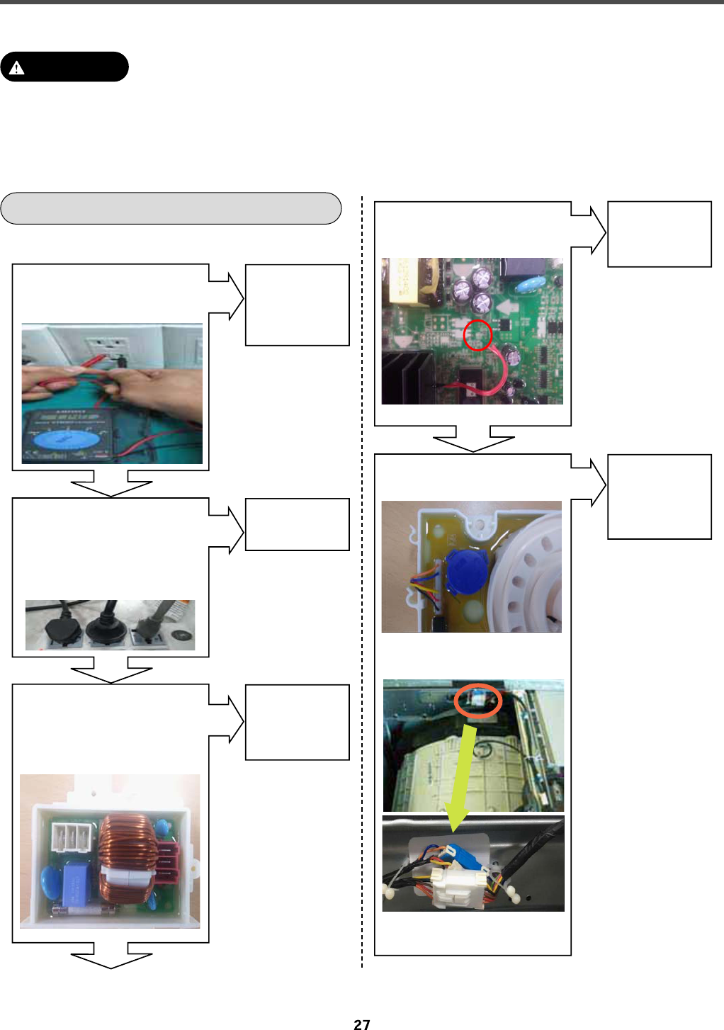
8-5. TROUBLESHOOTING ELSE
NO POWER
1. Be careful of electric shock if disconnecting parts while troubleshooting.
2. First of all, check the connection of each electrical terminal with the wiring diagram.
3. If you replace the MAIN PWB ASSEMBLY, reinsert the connectors correctly.
CAUTION
Check the
fuse or reset
the circuit
breaker.
Yes
No
Is the current rating of
multi-outlet power strip
enough?
(Avoid connecting several
electric devices.)
Is the supplied voltage
120V AC?(+10%, -15%)
Alternate with
explanation.
Yes
Yes
No
Is the connector connected
to PCB/Noise filter
disconnected or
disassembled?
Reconnect
or repair
the connector.
No
Replace the
MAIN PWB
ASSEMBLY.
Yes
No
Is LED on while the power
is on?
Replace the
DISPLAY
PWB
ASSEMBLY.
Display PWB
Connecting connector
MAIN PWB~ Display PWB
No
Is five pin wire of
display PWB broken?
Copyright © 2016 - 2017 LG Electronics Inc. All rights
reserved. Only training and service purposes.

BUTTON DOESN’T WORK
28
Copyright © 2016 - 2017 LG Electronics Inc. All rights
reserved. Onl
y
training and service purposes.

5<
Copyright © 2016 - 2017 LG Electronics Inc. All rights
reserved. Only training and service purposes.

DETERGENT DOES NOT FLOW IN
Refer to
NO WATER
SUPPLY.
Yes
Yes
No
Has detergent been put in
the correct compartment
of the dispenser?
(1) Liquid chlorine Bleach Compartment
(2) Liquid fabric Softener Compartment
(3) Prewash Compartment
(4) Main Wash Compartment
Is the detergent caked or
hardened?
Is water supplied?
Check the
wiring.
No
Are receptacles correctly
connected to the terminals
of the INLET VALVE
ASSEMBLY?
Put the
detergent in
the correct
place.
Clean the
dispenser.
Yes
Yes
No
Pre wash
Main wash
: Detergent
(1) (4) (3) (2)
63
Copyright © 2016 - 2017 LG Electronics Inc. All rights
reserved. Only training and service purposes.

LIQUID DETERGENT/SOFTENER/
BLEACH DOES NOT FLOW IN
ABNORMAL SOUND
Is water supplied?
Yes
No
Are the plugs correctly
connected to the terminals of
the INLET VALVE
ASSEMBLY?
Is the motor bolt loosened?
Is the liquid detergent/
softener/bleach cap clogged?
Check the
wiring on the
dispenser.
Refer to
NO WATER
SUPPLY.
No
Is liquid detergent/softener/
bleach put in the correct
compartment of the drawer?
Put it in the
correct
compartment.
Clean the cap
and
container.
No
Yes
Yes
Yes
Secure the
bolt.
Is there friction noise coming
from the motor?
Check hall
sensor.
Replace If
defective.
Then check
stator.
Replace if
necessary.
Check rotor
for broken
magnets.
Replace rotor
if necessary.
Yes
No
Yes
(1) Liquid chlorine Bleach Compartment
(2) Liquid fabric Softener Compartment
(3) Prewash Compartment
(4) Main Wash Compartment
(1) (4) (3) (2)
Bleach cap
Softener
cap
Liquid detergent cap
64
Copyright © 2016 - 2017 LG Electronics Inc. All rights
reserved. Only training and service purposes.

{G{GvGGGGGGG
GsnGzGk˞SGjGkSGG
sGzGGGGGG
GGGGGGU
XGGkGGsnGzGsMk~GhGG
GGU
YGG{GGGumjGOuGmGjPG
GGGGU
{G{GvGGGGGGGG
GGGGGumjGGG
GGGhGGGOvzPU
̰
G{GGGumjGGGGG
XG lGGIzIGG
GGGGG
GIzGMGjIG
GI~pylslzzGMG
ul{~vyrzˉU
YG zGIumjˈGGˈkG
hGiˉGGvuGG
GˈumjˈUG
ZG jGI|GyGG~V
wYwGˉU
Guv{l
G侩GkGGGGGG
GhGvzGSGGumjGG
GGUGyGGGGGG
GGGU
̰
G{G{GvG
G
侩
G{GvG
GsGGG{GvGGGGGslkG
GGGGUG{GGGG
GGGGGGG{GvG
GGGsnGzGk˞SGjG
kSGGsGzGGGGsnG
zGsMk~GU
~GGGG{GvGSGGG
GGGGGumjGGGGGG
GGGGGGGG{G
vGGGGUGpGGGGGG
GGGumjG
SGGGGGGGGG
GGGGGGG
U
iGGGGGumjSGGG
GGGGSGGGGGGG
GGGGGGGSGG
GGGUGpGGSGumjTG
GGGGGGGU
wG
GGGsnGzGsMk~GGGG
GGGGGGGG{GvG
U
7-5. Before using the Tag On function
65
Copyright © 2016 - 2017 LG Electronics Inc. All rights
reserved. Only training and service purposes.

8-1. FILTER ASSEMBLY (LINE FILTER)
8. COMPONENT TESTING INFO RM ATION
When Resistance (Ohm) checking the Component, be sure to turn t he power o,
and do voltage discharge suciently.
WARNING
Wiring
diagram
Circuit in the MAIN PWB / Wiring Diagram
Vac
MAIN PW B
ASSE MBLY
FUSE
RD1WH1
LI L2
RICI
C2
C3
3
2
1
3
2
1
Test
points
and
Result
Test Points Result
WH (1) to RD (3)
WH (3) to RD (1)
0
0
Copyright © 2016 - 2017 LG Electronics Inc. All rights
reserved. Onl
y
training and service purposes.
OZP
OXP
~oX
OZP
OXP
ykX
˟
˟

8-2. DOOR LOCK SWITCH ASSEMBLY
Wiring
diagram
Circuit in the MAIN PWB / Wiring Diagram
MAIN PWB
Vdc
Vac
MICOM
12V
4
1
3
2
4
1
3
2
Relay
Relay
NA4
1
2
3
4
1
2
3
4
2
3
4
PTC
PTC
Door switch
SOLENOID
5
YL
BL
RD
BK
AC
Common
terminal
of valve
Function
The door lock switch assembly consists of a heating PTC, a bimetal,
a protection PTC, and a solenoid. It locks the door during the wash cycle.
1.Operation for door closing
- After the system turns on, PTC heating starts up through terminals 2 and
4 authorizing the power on.
- After PTC heating starts up and before solenoid operation is driven,
force the system to the off position through CAM.
Door close
- Authorizing one impulse through terminal 3~4 (PTC & solenoid) will
make the door locked.
- Door lock is detected when switches in terminal 4~5 are set closed.
CAM rotation will forcibly clear off the connection.
The maximum, allowable number of impulse authorizations is 2.
Upon the third authorization of the impulse, the position of CAM goes
back to the door-open position.
- Authorizing the impulse occurs in 4.5 seconds upon input for max
performance and two authorization processes are allowed at most.
Normal operation period of PTC heating: 1.5 – 5 seconds.
(Defects from the development process.)
2.Operation for door opening
- With a temporary stop, door automatically opens by CAM rotations after
authorizing the impulse from the terminal, 3 ~ 4 and the power turns
off – maximum of 3 times of the authorizing period.
- Upon the fourth authorization of the impulse, the position of CAM goes
back to the door-close position.
67
Copyright © 2016 - 2017 LG Electronics Inc. All rights
reserved. Only training and service purposes.

Test
points
Result
Test Points
(2) to (4)
(3) to (4)
(4) to (5)
(2) to (4)
Result
700-1500 ˟
60-90 ˟
Infinity
120 Vac
Remarks
At 77
°F (25°C)
At 77
°F (25°C)
Voltage Input
͙͚ͦ ͙͚ͤ
͙͚͙͚ͣͥ
68
Copyright © 2016 - 2017 LG Electronics Inc. All rights
reserved. Only training and service purposes.

8-3. STATOR ASSEMBLY
Wiring
diagram
C irc uit in the MAIN P WB Wiring Diagram
MAIN PWB
MICOM
MOTOR
YL
w
wvu
v
u
BL
RD
4DRDR
IPM
YL
w
u
v
BL
RD
1
2
3
1
2
3
1
2
3
1
2
3
1
3
2
2
1
3
Function
Test points
(Windings)
Result
(Windings)
steps in either direction.
There are 36 poles on the stator; 12 permanent magnets spaced around the rotor.
There are no brushes to wear out. Unlike a more traditional brushless motor, the
rotor surrounds the stator rather than being attached to it.
Test Points Result
(1) to (2)
(2) to (3)
(3) to (1)
5-15
5-15
5-15
WINDINGS
(1)
(2)
(3)
Copyright © 2016 - 2017 LG Electronics Inc. All rights
reserved. Onl
y
training and service purposes.
˟
˟
˟

8-4. PUMP MOTOR ASSEMBLY
Wiring
diagram
Circuit in the MAIN PWB Wiring Diagram
MICOM
IC
R
5V
Rg
Cg
Vdc
Rs
Cs
PCB
CONNECTOR
PUMP
Vac
2
14
3
Pump Driving circuit
MAIN PWB
NA2
123 12 3
321
321
123
4
1234
BL3
SB
SB
NB KB
BN
DRAIN
PUMP
BK
Object
Function
Test
points
Result
* Each circuits of loads in wiring diagram are all same.
Two pump motors are used to drain t he tub
Drain Pump
Drain Pump
Test Points Result
(1) to (2) 10-20 Ω
T. P
(1) (2)
(1) (2)
37
Copyright © 2016 - 2017 LG Electronics Inc. All rights
reserved. Onl
y
trainin
g
and service purposes.

8-5. INLET VALVE ASSEMBLY
6;
Copyright © 2016 - 2017 LG Electronics Inc. All rights
reserved. Only training and service purposes.

_T]UG{olytpz{vyGhzzltis
Circuit in the MAIN PCB / Wiring Diagram
Copyright © 2016 - 2017 LG Electronics Inc. All rights
reserved. Onl
y
trainin
g
and service purposes.
39

Result
Wash Thermistor
Test Points
(1) to (2)
Result
(tolerance ±5%)
39.5 k˟
26.1 k˟
12.1 k˟
8.5 k˟
3.8 k˟
2.8 k˟
Remarks
At 86°F (30°C)
At 104°F (40°C)
At 140°F (60°C)
At 158°F (70°C)
At 203°F (95°C)
At 221°F (105°C)
Copyright © 2016 - 2017 LG Electronics Inc. All rights
reserved. Only training and service purposes.
40

Be sure to unplug the machine before disassembling and repairing the parts.
CONTROL PANEL
1
Unscrew 2 screws on the back of the top plate.
2
Pull the top plate backward and upward as
shown.
3
Disconnect the Display PWB assembly
connector from the cabling.
4
Pull out the drawer and unscrew 2 screws.
5
Remove one screw.
6
Lift the side the control panel assembly and
pull it out.
7
Unscrew the 8 screws from the control panel
assembly.
8
Disassemble the display PWB assembly.
9
Disconnect the NFC connector.
10
Disassemble the NFC PCB from the
PCB assembly, display
TOP PLATE ASSEMBLY
CONTROL PANEL ASSEMBLY
DRAWER
CONTROL PANEL ASSEMBLY
DISPLAY PWB ASSEMBLY
9. DISASSEMBLY INSTRUCTIONS
Copyright © 2016 - 2017 LG Electronics Inc. All rights
reserved. Only training and service purposes.
41

MAIN PWB ASSEMBLY
Disconnect the POWER connector and
the pressure switch assembly.
Remove the protective cover.
Unscrew 1 screw on the back.
Remove the main PWB.
Disconnect the connectors.
PROTECT COVER
1
2
3
4
5
75
Copyright © 2016 - 2017 LG Electronics Inc. All rights
reserved. Only training and service purposes.

DISPENSER ASSEMBLY
Disassemble the top plate assembly.
Pull out the drawer.
Push out the dispenser assembly after
unscrewing 2 screws.
NOISE FILTER
Disassemble two (or three) connectors from
the noise filter.
Unscrew a screw from the top bracket.
Unscrew the clamp nut at the lower part of the
dispenser.
Unscrew 2 screws from the back of the cabinet.
Disassemble the 4 connectors from the valves.
Wire Color
Blue Housing (YL-BK)
White Housing (WH-BK)
Blue Housing (GY-BK)
Red Housing (BL-BK)
1
2
3
4
DRAWER
1
3
2
4
5
6
1
2
76
Copyright © 2016 - 2017 LG Electronics Inc. All rights
reserved. Only training and service purposes.

CABINET COVER
Unscrew the 5 screws from upper of the
cabinet cover.
Unscrew the screw from the filter cover.
Put a flat ( - ) screwdriver or putty knife into the
hinge slots at the bottom of the cover and pry
it out.
Unscrew the screw from the lower side of the
cabinet cover.
1
2
3
4
77
Copyright © 2016 - 2017 LG Electronics Inc. All rights
reserved. Only training and service purposes.

Open the door.
Disassemble the clamp assembly.
Tilt the cabinet cover.
Disconnect the door switch connector.
Disassemble the clamp assembly.
Disassemble the gasket.
Lift and separate the cabinet cover.
NOTE : When assembling the
cabinet cover, connect the door switch
connector.
5
6
7
8
9
10
11
78
Copyright © 2016 - 2017 LG Electronics Inc. All rights
reserved. Only training and service purposes.

Open the door.
Unscrew the 4 screws from the hinge.
(Use the 8mm tool.)
Open the door and remove the gasket using
the special gasket pliers.
Unscrew the 2 screws.
Disassemble the door upward.
NOTE
• Reconnect the connector after replacing
the door switch assembly.
1
3
1
2
2
DOOR
DOOR LOCK SWITCH ASSEMBLY
79
Copyright © 2016 - 2017 LG Electronics Inc. All rights
reserved. Only training and service purposes.
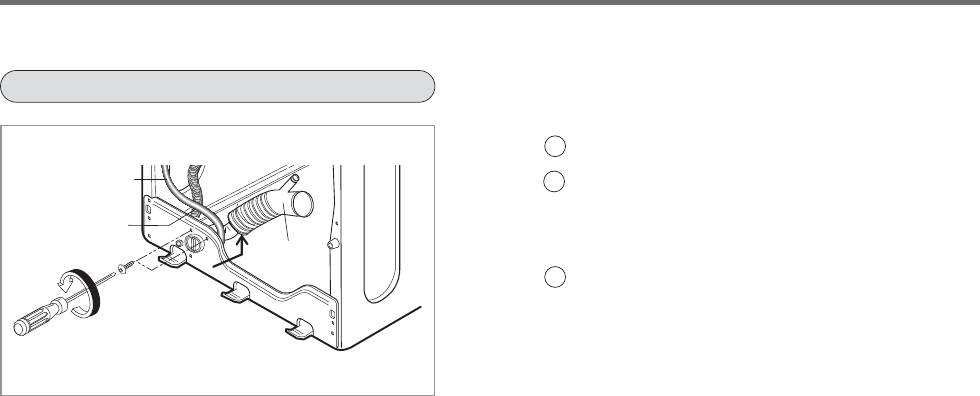
w|tw
kGGGU
zGGGSGGSG
GGGGG
U
kGGGU
jpyj|sh{pvu
ovzl
w|twGovzl
ilssv~z
X
Y
Z
[^
Copyright © 2016 - 2017 LG Electronics Inc. All rights
reserved. Onl
y
trainin
g
and service purposes.

WHEN FOREIGN OBJECT IS STUCK BETWEEN DRUM AND TUB
Disassemble the cabinet cover.
Separate the heater from the tub.
Remove any foreign objects (wire, coin, etc.)
by inserting a long bar in the opening.
LAMP ASSEMBLY
Unscrew 2 screws on the back of the top plate.
Pull the top plate backward and upward as
shown.
TOP PLATE ASSEMBLY
1
2
3
1
Disconnect the connector.
3
2
7;
Copyright © 2016 - 2017 LG Electronics Inc. All rights
reserved. Only training and service purposes.

tv{vyVkhtwly
uv{lG
pGGGGGSGGGG
UGpGGGGGSGG
GGTUG
i
y
khtwly
opunlS
khtwly
kGGGU
yGGU
wGGGU
X
Y
Z
|GGYGGGGGU
yGG]GGGGU
|GGXGGGGU
X
Y
Z
kGGGGGG
GU
X
Copyright © 2016 - 2017 LG Electronics Inc. All rights
reserved. Onl
y
trainin
g
and service purposes.
49

M410
*Non-Skid pads
G010
F110
A104
A105 A106
A102
A103
A101
A100
A430
A440
A220
A200
A303
A310
A300
A133
A140
A130
A151 A153
A390
A131
A141
A152
A156
A410
A455
A485
A150
A154
A450
F210
F215
A110
A111
A175

F326
K143
K123
K610
K360
K611
K200
K411
K410
K110
K111
K140
K142
K320
K510
K512
K135
K530
K131
K344
K340
K346
K349
K342
K348
K347
K345
F365
F145
F468
K130
K520
K540
K550
K105
F468
F464
K190
K516
F464
F463
F310
K141
F315
F360
F140
K571
K570
0

F160
F300
F323
F322
F462
F321
F227 F226
F220
.
.
F225
F430
F120
F130
F432
F170
F327
F329

11.Wiring Diagram
Copyright © 2016 - 2017 LG Electronics Inc. All rights
reserved. Onl
y
training and service purposes.
53

P/No.
MFL68588909
