
Thermo King has a policy of coninuous product and data improvements and reserves the right to change design and specications without notice. We are
committed to using environmentally conscious print practices.
Thermo King – by Trane Technologies (NYSE: TT), a global climate innovator – is a worldwide leader in sustainable
transport temperature control solutions. Thermo King has been providing transport temperature control solutions
for a variety of applications, including trailers, truck bodies, buses, air, shipboard containers and railway cars since
1938. For more information, visit www.thermoking.com or www.tranetechnologies.com
©2020 Trane Technologies
TK 61110-4-OP Nov 2013
Operator’s Manual
Manuel de l’utilisateur
Manual del operador
Betriebshandbuch
Bruksanvisning
MagnumPlus
November 2013
Revision 0
TK-61110-4-OP

Magnum +
TK 61110-4-OP (Rev. 0, 11/13)
En


1
TABLE OF CONTENTS
TABLE OF CONTENTS
Table of Contents . . . . . . . . . . . . . . . . . . . . . . . . . 1
Safety Instructions . . . . . . . . . . . . . . . . . . . . . . . . 2
General Precautions .......................................... 2
Electrical Precautions ........................................ 2
Precautions ........................................................ 2
First Aid ............................................................ 3
Low Voltage ...................................................... 3
Identifying Unit Safety and Warning Decals .... 5
Locating Serial Numbers .................................. 5
Unit Inspection . . . . . . . . . . . . . . . . . . . . . . . . . . . 6
Specifications . . . . . . . . . . . . . . . . . . . . . . . . . . . . 8
System Net Cooling Capacity— Full Cool ....... 8
Evaporator Airflow Specifications .................... 8
MP-4000 Controller Specifications .................. 11
Physical Specifications ..................................... 13
Unit Description . . . . . . . . . . . . . . . . . . . . . . . . . . 14
Introduction ....................................................... 14
General Description .......................................... 14
Controller Description . . . . . . . . . . . . . . . . . . . . . 16
Controller Description ....................................... 16
Standard Display ............................................... 17
Glossary of Symbols ......................................... 18
Glossary of Mode Descriptions ........................ 19
Navigating the Controller Operating Menu . . . . . 22
Menu Scrolling Keys ........................................ 22
Initiating a Manual Defrost ............................... 23
PTI .................................................................... 24
Viewing Alarms/Warnings ............................... 24
Display Alternate Fahrenheit (F) or Celsius (C)
Temperatures .................................................. 24
Changing Setpoint ............................................ 24
Controller Back-up Battery ............................... 24
Operating Theory . . . . . . . . . . . . . . . . . . . . . . . . . 26
MAGNUM+ Operating Mode Function Chart . 26
Diagnosis: Troubleshooting, Warnings and Alarm
Codes . . . . . . . . . . . . . . . . . . . . . . . . . . . . . . . . . . 28
Introduction ....................................................... 28
Controller Diagnostics ...................................... 28
Emergency Cold Line . . . . . . . . . . . . . . . . . . . . . . 30
DECLARATION . . . . . . . . . . . . . . . . . . . . . . . . . 31

2
SAFETY INSTRUCTIONS
SAFETY INSTRUCTIONS
GENERAL PRECAUTIONS
• Always wear goggles or safety glasses.
Refrigerant liquid and battery acid can
permanently damage the eyes.
• Never operate the unit with the discharge
valve closed. Never close the compressor
discharge valve with the unit in operation.
• Keep your hands, clothing and tools clear of
the fans when the refrigeration unit is
running. If it is necessary to run the
refrigeration unit with covers removed, be
very careful with tools or meters being used
in the area.
• Never apply heat to a sealed refrigeration
system or container.
• Fluorocarbon refrigerants produce toxic
gases in the presence of an open flame or
electrical arc. The gases are severe
respiratory irritants capable of causing death.
• Firmly tighten all mounting bolts. Check
each bolt for correct length for their
particular application.
• Use caution when working around exposed
coil fins. The fins can cause painful
lacerations.
• Use caution when working with a refrigerant
or refrigeration system in any closed or
confined area with a limited air supply (for
example, a trailer, container or in the hold of
a ship). Refrigerant tends to displace air and
can cause oxygen depletion. This can result
in suffocation and possible death.
• Use caution and follow the manufacturer’s
suggested practices when using ladders or
scaffolds
.
ELECTRICAL PRECAUTIONS
The possibility of serious or fatal injury from
electrical shock exists when servicing a
refrigeration unit. Extreme care must be used
when working with a refrigeration unit that is
connected to its power source. Extreme care
must be used even if the unit is not running.
Lethal voltage potentials can exist at the unit
power cord, inside the control box, inside any
high voltage junction box, at the motors and
within the wiring harnesses.
PRECAUTIONS
In general disconnect the units power cord
before repairing or changing any electrical
components.
Note that even though the controller is turned
off, one of the phases is still live and represents
a potential danger of electrocution
Where turning of the unit is not possible (for
example at voltage measuring or
troubleshooting), follow safety precautions
below.
• Turn the unit On/Off switch to Off before
connecting or disconnecting the unit power
plug. Never attempt to stop the unit by
disconnecting the power plug.
• Be certain the unit power plug is clean and
dry before connecting it to a power source.
• Use tools with insulated handles. Use tools
that are in good condition. Never hold metal
tools in your hand if exposed, energized
conductors are within reach.
• Do not make any rapid moves when working
with high voltage circuits. Do not grab a
falling tool or other object. People do not
contact high voltage wires on purpose. It
occurs from an unplanned movement.
• Treat all wires and connections as high
voltage until ammeter and wiring diagram
show otherwise.
• Never work alone on high voltage circuits on
the refrigeration unit. Another person should
always be standing by in the event of an
accident to shut off the refrigeration unit and
to aid a victim.
• Have electrically insulated gloves, cable
cutters and safety glasses available in the
immediate vicinity in the event of an
accident.

3
SAFETY INSTRUCTIONS
FIRST AID
IMMEDIATE action must be initiated after a
person has received an electrical shock. Obtain
immediate medical assistance.
The source of shock must be immediately
removed. Shut down the power or remove the
victim from the source. If it is not possible to
shut off the power, the wire should be cut with
either an insulated instrument (e.g., a wooden
handled axe or cable cutters with heavy
insulated handles). A rescuer wearing
electrically insulated gloves and safety glasses
could also cut the wire. Do not look at the wire
while it is being cut. The ensuing flash can
cause burns and blindness.
Pull the victim off with a non-conductive
material if the victim has to be removed from a
live circuit. Use the victim’s coat, a rope, wood,
or loop your belt around the victim’s leg or arm
and pull the victim off. Do not touch the victim.
You can receive a shock from current flowing
through the victim’s body.
Check immediately for the presence of a pulse
and respiration after separating the victim from
power source. If a pulse is not present, start
CPR (Cardio Pulmonary Resuscitation) and
call for emergency medical assistance.
Respiration may also be restored by using
mouth-to-mouth resuscitation.
LOW VOLTAGE
Control circuits are low voltage (24 Vac and 12
Vdc). This voltage potential is not considered
dangerous. Large amount of current available
(over 30 amperes) can cause severe burns if
shorted to ground. Do not wear jewelry, watch
or rings. These items can shortcut electrical
circuits and cause severe burns to the wearer.
4
SAFETY INSTRUCTIONS
2
BEN074
AXA0214
AXA0215
AXA0218
AXA0217
AXA0216
1
3
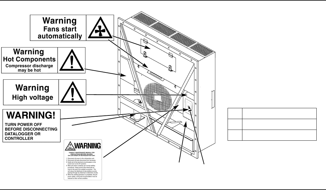
Nameplate and Warning Locations
1. Controller Nameplate
2. Unit Nameplate
3. Compressor Nameplate

5
SAFETY INSTRUCTIONS
IDENTIFYING UNIT SAFETY AND
WARNING DECALS
Serial number decals, refrigerant type decals
and warning decals appear on all Thermo
King
®
equipment. These decals provide
information that may be needed to service or
repair the unit. Service technicians should read
and follow the instructions on all warning
decals. See Figure .
LOCATING SERIAL NUMBERS
Serial numbers can be found on the
component’s nameplate.
• Electric Motor Nameplate: Attached to the
motor housing.
• Compressor Nameplate: On front of the
compressor.
• Unit Nameplate: On unit frame in power
cord storage compartment.
• MP-4000 Controller Nameplate: On top of
controller.

6
UNIT INSPECTION
UNIT INSPECTION
A closely followed maintenance program will help to keep your Thermo King unit in top operating condition.
The following service guide table should be used as a guide when inspecting or servicing components on this unit.
If a unit has been carrying cargo which contains a high level of sulphor or phosphorous (e.g. garlic, salted fish etc.), it is recommended that
clean evaporator coil after each trip.
Pretrip Inspect These Items
Electrical
• Perform a controller pretrip inspection (PTI) check.
• Visually check condenser fan and evaporator fan.
• Visually inspect electrical contacts for damage or loose connections.
• Visually inspect wire harnesses for damage or loose connections.
Refrigeration
• Check refrigerant charge.
Structural
• Visually inspect unit for damaged, loose or broken parts.
• Tighten unit, compressor and fan motor mounting bolts.

7
UNIT INSPECTION

8
SPECIFICATIONS
SPECIFICATIONS
SYSTEM NET COOLING CAPACITY— FULL COOL
EVAPORATOR AIRFLOW SPECIFICATIONS
MAGNUM+ Model — Air Cooled Condensing*
Return air to evaporator coil inlet
460/230V, 3 Phase, 60 Hz Power
Net Cooling Capacity Power Consump
60 Hz Capacity B/hr 60 Hz Capacity kW 60 Hz Power kW
21.1 C (70 F) 56,700 16.603 11.55
1.7 C (35 F) 40,945 11.990 11.03
-17.8 C (0 F) 24,785 7.258 7.57
-29 C (-20 F) 17,215 5.041 6.6
-35 C (-31 F) 14,000 4.104 6.03
*System net cooling capacity with a 38 C (100 F) ambient air temperature and R-404A.
460/230V, 3 Phase, 60 Hz Power 380/190V, 3 Phase, 50 Hz Power
Heating Capacity Heating Capacity
Watts Kcal/hr BTU/hr Watts Kcal/hr BTU/hr
MAGNUM+ normal 5,250 4,515 17,914 3,900 3,353 13,300
MAGNUM+ extended 7,250 6,234 24,738 5,550 4,772 18,937
*System net heating capacity includes electric resistance rods and fan heat.

9
SPECIFICATIONS
MAGNUM+
External Static
Pressure (water
column)
460/230V, 3 Phase, 60 Hz Power 380/190V, 3 Phase, 50 Hz Power
High Speed Low Speed High Speed Low Speed
m
3
/hr ft
3
/min m
3
/hr ft
3
/min m
3
/hr ft
3
/min m
3
/hr ft
3
/min
0 mm (0 in.) 6,560 3,860 3,170 1,865 5,480 3,225 2,710 1,595
10 mm (0.4 in.) 5,820 3,425 1,770 1,040 4,530 2,665 930 545
20 mm (0.8 in.) 5,000 2,940 — — 3,750 2,205 — —
30 mm (1.2 in.) 4,430 2,610 — — 2,930 1,725 — —
40 mm (1.6 in.) 3,520 2,070 — — 1,870 1,100 — —
Compressor Motor:
Type 460/380V, 60/50 Hz, 3 Phase
Kilowatts 4.48 kW @ 460V, 60 Hz
Horsepower 6.0 hp @ 460V, 60 Hz
RPM 3550 RPM @ 460V, 60 Hz
Locked Rotor Amps 70 amps @ 460V, 60 Hz
Condenser Fan Motor:
Type 460/380V, 60/50 Hz, 3 Phase
Kilowatts 0.55 kW @ 460V, 60 Hz
Horsepower 0.75 hp @ 460V, 60 Hz
Number: All Models 1
Motor:
RPM 1725 RPM @ 460V, 60 Hz
Full Load Amps 1.0 amps @ 460V, 60 Hz; 1.0 amps @ 380V, 50 Hz

10
SPECIFICATIONS
Locked Rotor Amps 3.9 amps @ 460V, 60 Hz; 3.7 amps @ 380V, 50 Hz
Evaporator Fan Motors:
Type 460/380V, 60/50 Hz, 3 Phase
Kilowatts 0.75 kW @ 460V, 60 Hz
Horsepower 1.0 hp @ 460V, 60 Hz
Motor:
RPM (Each): High Speed 3450 RPM @ 460V, 60 Hz
Low Speed 1725 RPM @ 460V, 60 Hz
Full Load Amps (Each): High Speed 1.6 amps @ 460V, 60 Hz
Low Speed 0.8 amps @ 460V, 60 Hz
Locked Rotor Amps: High Speed 10.5 amps @ 460V, 60 Hz
Low Speed 9.0 amps @ 460V, 60 Hz
Electrical Resistance Heater Rods:
Type 460/380V, 60/50 Hz, 3 Phase
Number
Normal Capacity
Normal Capacity
Extended Capacity
6 (18 ga wire)
3 (18 ga wire)
3 (16 ga wire)
Watts (Each):
Normal Capacity
Normal Capacity
Extended Capacity
680 Watts @ 460V, 60 Hz
1360 Watts @ 460V, 60 Hz
2000 Watts @ 460V, 60 Hz
Current Draw (Amps) 5 amps total @ 460V across each phase at heater contractor
Control Circuit Voltage:
29 Vac @ 60 Hz

11
SPECIFICATIONS
MP-4000 CONTROLLER SPECIFICATIONS
Temperature Controller:
Type MP-4000 is a controller module for the Thermo King Magnum+ Unit. Additional
requirements can be met by means of expansion modules. The MP4000 is solely
responsible for temperature regulation of the reefer container, but other monitoring
equipment can be used in conjunction with the MP 4000 - such as a chart recorder.
Setpoint Range -40.0 to +30.0 C (-31.0 to +86.0 F)
Digital Temperature Display -60.0 to +80.0 C (-76.0 to +176.0 F)
Controller Software (Original Equipment):
Version See controller identification decal
Defrost Initiation:
Evaporator Coil Sensor Manual Switch or Demand Defrost Initiation: Coil must be below 18 C (65 F).
Defrost cycle starts when technician or controller requests defrost initiation.
Timed Defrost Initiation: Coil must be below 4 C (41 F). Defrost cycle starts 1
minute after the hour immediately following a defrost timer request for defrost
initiation. For example, if the defrost timer requests a defrost cycle at 7:35, the
defrost cycle will start at 8:01. Datalogger will record a Defrost event for each interval
in which a Defrost cycle is pending or active (i.e. both the 8:00 and 9:00 data logs).
Demand Defrost Demand defrost function initiates defrost when:
Temperature difference between the return air sensor and defrost (evaporator coil)
sensor is too large for 90 minutes
Temperature difference between the supply air sensors and return air sensor is too
large
Defrost Timer:
Chilled mode
Evaporator Coil Temperature must be below 5C (41 F) to activate the defrost
compressor hour timer.

12
SPECIFICATIONS
Chilled Mode (continued) There is an interval set for defrosting, however, the defrost timer is built intelligent - it
detects whether or not there is ice building up on the coil. If there is no ice building up
on the coil, it extends the defrost interval, and if there is Ice building up earlier on the
coil it reduces the defrost interval. The maximum interval is 48 hours.
Frozen mode Every 8 hours of compressor operation. Defrost interval increases 2 hours each
timed defrost interval. Maximum time interval in Frozen mode is 24 hours.
Reset to Base Time Defrost timer resets if the unit is off more than 12 hours, setpoint is changed more
than 5 C (9 F) or PTI pretrip test occurs.
Defrost Termination:
Defrost (Coil) Sensor Chilled mode: Terminates defrost when coil sensor temperature rises to 18 C (65 F).
Frozen mode: Terminates defrost when coil sensor temperature rises to 18 C (65 F).
Termination Timer Terminates defrost after 90 minutes at 60 HZ operation if coil sensor has not
terminated defrost (120 minutes at 50 Hz operation)
Power Off Turning Unit On/Off switch Off terminates defrost
MP-4000 CONTROLLER SPECIFICATIONS (CONTINUED)

13
SPECIFICATIONS
Compressor Shutdown Protection (Auto Reset):
Stops Compressor 148 C (298 F)
Allows Compressor Start 90 C (194 F)
Bulb Mode:
Evaporator Fan Speed Settings Flow High: High speed only
Flow Low: Low speed only
Flow Cycle: Fans will cycle between low and high speed every 60 minutes
Defrost Termination Temperature Setting 4 to 30 C (40 to 86 F)
PHYSICAL SPECIFICATIONS
Fresh Air Exchange Venting System (Adjustable):
MAGNUM+ 0 to 225 m
3
/hr (0 to 168 ft
3
/min.) @ 60 Hz
0 to 185 m
3
/hr (0 to 139 ft
3
/min.) @ 50 Hz
Evaporator Fan Blade Specifications:
MAGNUM+:
Diameter 355 mm (14.0 in.)
Pitch 25°
Number of Fans 2
Weight (net):
MAGNUM+ Base Unit 380 Kg (875 lb.)
Water-cooled Condenser-Receiver Option 13.6 Kg (30 lb.)
MP-4000 CONTROLLER SPECIFICATIONS (CONTINUED)

14
UNIT DESCRIPTION
UNIT DESCRIPTION
INTRODUCTION
This chapter will briefly describe the following
items:
• General Unit Description.
• Standard Component Descriptions.
• Optional Component Descriptions.
GENERAL DESCRIPTION
MAGNUM units are all-electric, single-piece,
refrigeration units with bottom air supply. The
unit is designed to cool and heat containers for
shipboard or overland transit. The unit mounts
in the front wall of the container. Fork lift
pockets are provided for installation and
removal of the unit.
The frame and bulkhead panels are constructed
of aluminum and are treated to resist corrosion.
A removable evaporator compartment door
provides service access. All components except
the evaporator coil and electric heaters can be
replaced from the front of the unit.
Each unit is equipped with an 18.3 m (60 ft.)
power cable for operation on 460-380V/3 Ph/
60-50 Hz power. The unit power cable is stored
below the control box in the condenser section.
Each unit is equipped with 460-380V/3 Ph/
60-50 Hz electric motors. An automatic phase
correction system provides the proper electrical
phase sequence for condenser fan, evaporator
fan and compressor operation.
Figure 1: MAGNUM+ Unit
BEN074

15
UNIT DESCRIPTION
The MAGNUM+ container unit features the
following components:
• Scroll Compressor
• Compressor Digital Control Valve
• Economizer Heat Exchange System
• Temperature Sensors
• Fresh Air Exchange System
• Receiver Tank Sight Glass
• Evaporator Fans
• Condenser Fan Control
• Suction/Discharge Pressure Sensor
(Optional)
• Remote Monitoring Receptacle Option
(4-pin) (optional)
• Remote Monitoring Modem (RMM,
RMM+) (Optional)
• USDA Cold Treatment Temperature
Recording (Optional)
• Advanced Fresh Air Management (AFAM)
and Advanced Fresh Air Management Plus
(AFAM+) (Optional)
MP-4000 Controller
The MP-4000 is an advanced microprocessor
controller that has been specially developed for
the control and monitoring of refrigeration
units. See “Controller Description and
Operating Chapter” for more detailed
information.
1
BEN074
1. MP-4000 Controller
Figure 2: MP-4000 Controller

16
Controller Description
CONTROLLER DESCRIPTION
CONTROLLER DESCRIPTION
The MP-4000 is an advanced microprocessor
controller. It has been specially developed for
the control and monitoring of refrigeration
units. The controller contains the following
basic features:
Temperature/Message Status Display:
• Temperature area. Displays Return air
sensor, Supply air sensor, and Setpoint
• Message area. Displays Alarms, Message
and Controller menu
Keypad:
• F1 – F4 Function keys navigate within the
Status Display
• 2 Status LED indicators
• Special Function keys. ON/OFF, PTI,
Defrost
Controller Back-up Battery
Every Controller has a Back-up Battery. This
will allow the controller to be energized if the
unit is not connected to shore power. The
technician can change settings in the controller
- Setpoint, etc.
Press the ON/OFF key, the controller will
energize and stay energized for 25 sec, by
pressing any of the Menu keys the 25 sec timer
will reset to 20 sec.
Controller Input and Output Signals
The MP-4000 microprocessor controls all unit
functions to maintain the cargo at the proper
temperature. The controller also monitors and
records system faults and performs pretrip.
The MP-4000 controller uses advanced
solid-state integrated circuits to monitor and
control unit functions. The controller monitors
inputs from:
• Return Air Sensor
• Supply Air Sensor
• Evaporator Coil Sensor
• Condenser Coil Sensor
• Ambient Sensor
• Humidity Sensor
• USDA (Spare) Sensors 1, 2 and 3
• Compressor Discharge Line Temperature
Sensor
• High Pressure Cutout Switch/Discharge
Pressure Sensor
• Low Pressure Cutout Switch/Suction
Pressure Sensor
• Phase measuring circuits
• Current measuring circuits
• Voltage measuring circuits
Output signals from the controller
automatically regulate all unit functions
including:
• Compressor operation
• Condenser fan operation
• Evaporator fan motor operation
• Compressor digital valve
• Vapor injection valve
• Dehumidify valve
• Electric heaters
• Phase selection

17
Controller Description
STANDARD DISPLAY
The Standard Display is a ¼ VGA graphical
type display. The temperature can be displayed
in Celsius or Fahrenheit.
The standard display will display the
controlling sensor and Setpoint. The Setpoint
will be the low reading with the C or F.
Once a key is pressed the Standard display will
change to the Unit Status Display. After 2 min
of no key activity the display will return the
Standard display
Standard Display
Idle Screen
After approximately 30 seconds of inactivity
the display will go into hibernation and one of
the following symbols will be displayed.
Display alternates between the Idle screen and
the standard display during this time.
The happy face => everything is ok
The Disgruntled face => we do have a
warning
The unhappy face => we do have an
alarm
Check Mark Symbol
The check mark symbol
indication that a SmartPTI has
recently been running and no
problems was found. The
thumb will only be shown in
the normal operation state.
This symbol will appear at the
left hand corner of the idle screen display.
1. Standard Display
2. Function Keys
3. Special Function Keys
MP-4000 Controller Display Panel
3
2
1
18
Controller Description
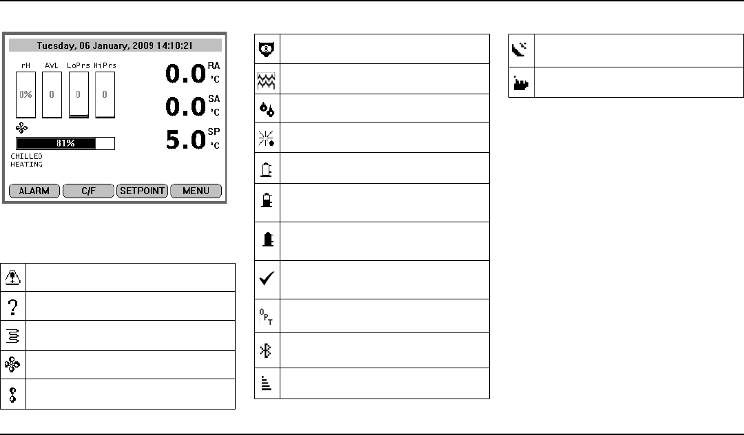
Unit Status Display
Unit Status Display
The Unit Status display will show.
Looking at the display from top to bottom
• Date and Time / Alarm Warning
• rH Relative Humidity sensor
• AVL Door Position/AFAM+
• LoPrs Low Pressure Transducer
• HiPrs High Pressure Transducer
• RA Return air sensor
• SA Supply air sensor
• SP Setpoint
• Mode Icons Compressor ON, Heater
ON, Evap Fan ON
• Capacity Bar Graph Percentage of
mode (100% is full on)
GLOSSARY OF SYMBOLS
- Alarm
- Pretrip Inspection / Test in Progress
- Heating
- Evaporator Fan High Speed
- Evaporator Fan Low Speed
- Condenser Fan On
- Watercooled
- Dehumidification
- Defrost
- Compressor On Unloaded
- Compressor On loaded without
Vapour Injection
- Compressor On loaded with Vapour
Injection
- SmartPTI has recently been runnning
and no problems found
- Controlling mode optimized
- Bluetooth
- Cell Phone
GLOSSARY OF SYMBOLS
- GPS Signal
- RMM
GLOSSARY OF SYMBOLS

19
Controller Description
• Mode Description Descript unit
operation
• F1 – f4 Key Functions ALARM C/F
SETPOINT MENU
GLOSSARY OF MODE
DESCRIPTIONS
Chilled/cooling
Chilled cooling is a mode where the Unit
setpoint is set to above -10C. The function here
is to maintain setpoint temperature by
controlling the temperature on the supply air.
The supply air is not allowed to be lower than
the setpoint. Chilled/cooling mode can operate
the unit in different modes where the
compressor can run loaded, unloaded/loaded
and vapor injection depending on the need for
cooling capacity. The condenser fan will
operate in an on/off algoritim depending on the
temperature on the condenser. The evaporator
fans will operate in either high or low speed
mode depending on the need for capacity.
Chilled/heating
Chilled heating is a mode the Unit setpoint is
set to above -10C. The function here is to
maintain setpoint temperature by controlling
the temperature on the supply air.
The supply air is not allowed to be lower than
the setpoint. Chilled heating mode can operate
the unit where only the evaporator fan low
speed is running, evaporator high speed is
running or evaporator high speed and heat is
on.
Frozen/cooling down
Frozen/cooling down mode where the Unit
setpoint is set to below -10C. The function here
is to maintain setpoint temperature by
controlling the temperature on the return air.
Frozen/cooling down mode can operate the unit
in different modes where the compressor is
loaded and vapor injection is on/off. The
condenser fan will operate in an on/off
algoritim depending on the temperature on the
condenser. The evaporator fans will operate in
low speed mode or off.
Defrost
Defrost is a situation where the unit either on
demand or timing is defrosting the evaporator
coil. The unit is heating with the heating
elements awaiting 18C on the evaporator
sensor.
When the set Defrost termination temperature
is reached, the unit will return to the operation
mode depending on the setpoint.
PTI
PTI is a pretrip inspection and is used to
diagnose the condition of the unit. There are a
possibility to chose between several type of
PTI´s depending on the test needed to secure
the functionality of the unit.
Function Keys
The function keys are the F1 - F4 keys located
below the display. They allow the operator to
move quickly to a specific area of the
information or into the controller menu.
Function keys will change based on what menu
is active in the display
Function Keys
• F1 INFO key: Press to view an explaination
for the current alarms present.
• F2 C/F key: Press to view alternate
temperature scale Celsius or Fahrenheit in
display.
• F3 SETPOINT key: Press to enter Setpoint
menu. Press F2 Up or F3 Down keys to
increase or decrease the Setpoint. Press and

20
Controller Description
Hold F4 until you are returned back to the
main menu.
• F4 MENU key: Press to view the extended
Menu for the MP4000
Indicator LEDs
Two status indicator LEDs are located just
under the F1-F4 function keys
Three Special Function Keys
The Special Function keys are located around
the TK Logo. These special function key allow
the operator to move quickly to perform a
specific function
Special Function Keys
Green Led Flashing Temperature
approaching
in-range
Solid Temperature
In-Range
Red Led Flashing Alarm present and
has not been
acknowledged
Solid Alarm present and
has been
acknowledged
PTI Pre-Trip Inspecion
* Defrost
ON
OFF
Unit On/OFF Control

21
Controller Description

22
NAVIGATING THE CONTROLLER OPERATING MENU
NAVIGATING THE
CONTROLLER OPERATING
MENU
MENU SCROLLING KEYS
Moving through these seven menus, their
submenus and entering commands requires the
use of four keys:
EXIT - Press the F1 key each
time you want to exit a submenu
shown in the message display.
UP/ DOWN- Press the F2 or F3
key each time you want to scroll
up or down in a menu or
submenu shown in the Message
Display; or scroll forward or
backward in a menu line.
ENTER - Press the F4 key to
enter a new menu or submenu.
The MP-4000 contains an extensive operating
menu. The menu is navigated via the controller
keypad. There are 2 types of menu’s that can be
displayed
1. The Classic Main menu is divided into seven
major areas that can be navigated via
keypad.
Classic Menu
1
2
5
3
4
1. Classic Main Menu
2. Menu Scrolling Keys
3. ON/OFF Key
4. Defrost Key
5. PTI - Pre-trip Inspection
MP-4000 Controller Display Panel

23
NAVIGATING THE CONTROLLER OPERATING MENU
2. The icon Main menu is divided into 5 icons
(Alarms and warnings appear under “Info”
icon)
Icon Menu
LOCK PADLOCK
If PADLOCK is active, contact technicaian, the
technician must enter correct key (number) to
unlock display. PADLOCK OPTION must be
selected ON under the CONFIGURATION/
UNIT SETTING for it to be active or visible.
Lock Padlock
INITIATING A
MANUAL DEFROST
Turn the UNIT ON. Allow
Unit to start and stabilise.
Complete the following
steps:
1. Press the D
EFROST Special Function key.
• If the unit operating conditions allow
a manual defrost (e.g. evaporator coil
temperature is less than 18 C [56 F]),
the unit enters Defrost.
• Select Start Defrost.
2. The defrost cycle automatically terminates
and returns the unit to normal operation.

24
NAVIGATING THE CONTROLLER OPERATING MENU
PTI
Turn the UNIT ON. Allow
Unit to start and stabilise.
Complete the following
steps:
1.Press the PTI Special
Function key.
2. Press the F2/F3 keys to scroll down to select
from the different PTI test.
3. Press the F4 key to ACCEPT and start the
PTI or test.
VIEWING ALARMS/
WARNINGS
To view the alarms that are
present, turn the UNIT
ON.Allow Unit to start and
stabilise.
Complete the following
steps:
1. Press the F1
/ALARM KEY. The Alarm List
appears.
2. Press the F2/F3 keys to scroll between
Alarms that are present.
3. Press the F4 key to acknowledge the Alarm.
Press F1 again to exit.
DISPLAY
ALTERNATE
FAHRENHEIT (F)
OR CELSIUS (C)
TEMPERATURES
To view the alarms that are present, turn the
UNIT ON.Allow Unit to start and stabilise.
Complete the following step:
The controller can display temperatures in
Celsius or Fahrenheit. Press the F2 function
key display will change to C or F
To change the display to C or F permanently,
press and hold the F2 C/F key, then confirm
“ARE YOU SURE YES or NO. Some
customers do notallow the display to be change
permanently.
CHANGING
SETPOINT
To change the controller
setpoint, turn the UNIT
ON.Allow Unit to start and
stabilise.
Complete the following
steps:
1.Press the F3
key at the
main screen. The Setpoint Change menu
appears.
2. Press the F2/F3 keys to scroll the Setpoint
Up or down - depending on your required
Temperature.
3. Press and hold the F4 key until you are
returned to the main Screen. The new
setpoint is recorded in the controller and
appears in the display.
CONTROLLER BACK-UP BATTERY
Every Controller has a Back-up Battery. This
will allow the controller to be energized if the
unit is not connected to shore power. The
technician can change settings in the controller
- Setpoint, etc.
Press the ON/OFF key, the controller will
energize and stay energized for 25 sec, by
pressing any of the Menu keys the 25 sec timer
will reset to 20 sec.

25
NAVIGATING THE CONTROLLER OPERATING MENU

26
OPERATING THEORY
OPERATING THEORY
1
Setpoint temperature and controlling mode
setting determine the evaporator fan speed:
Normal Operation : Chill Loads — High
or low speed fans; Frozen Loads — Low speed
fans or no fans.
2
Vapor injection valve:
Chill, Frozen or Power Limit Mode:
When the cool capacity is 100 percent.
Compressor High Temperature
Protection:
When the compressor discharge
temperature exceeds 138 C (280 F).
3
Condenser fan pulses on and off on a 30
second duty cycle to maintain a minimum
condenser temperature:
Chill Loads: Controller maintains a
minimum 30 C (86 F) condenser temperature.
Frozen Loads: Controller maintains a
minimum 20 C (68 F) condenser temperature.
4
Digital Control valve modulates: Chill Loads
— whenever the unit is in a Cooling mode;
Power Limit — whenever the unit is in Power
Limit mode.
MAGNUM+ Operating Mode Function Chart
Chill Loads
Setpoints at -9.9 C
(14.4 F) and Above
Frozen Loads
Setpoints at -10 C
(14 F) and Below
Cool w/Mod Heat Defrost Cool Null Defrost Unit Function
•
1
• Evaporator Fans High Speed
1
•
1
••
1
Evaporator Fans Low Speed
1
••
1
• Evaporator Fans Off
1
• • Proportional-integral Derivative (Supply Air) Control
• • Return Air Sensor Control
• • Evaporator Coil Sensor Control
••Compressor On
• • Compressor Vapor Injection On (valve energized)
2
• • Condenser Fan On
3
••
4
Digital Control Valve Modulating (energized)
4
•
5
• • • Electric Heaters Pulsing or On (energized)
5

27
OPERATING THEORY
Dehumidification: When the Dehumidify
mode is set to On, the supply air temperature
must be In-range to energize the electric
heaters.
• When the humidity is 2 percent or more
above humidity setpoint, the controller
(energizes) the heaters.
5
Controller energizes electric heaters for heat,
defrost and dehumidification:
Heat mode (compressor off): If
supply air temperature is too low, heaters pulse
on and off on a 60 second duty cycle.
Defrost mode: Heaters are on until
evaporator coil temperature increases to
terminate defrost.

28
DIAGNOSIS: TROUBLESHOOTING, WARNINGS AND ALARM CODES
DIAGNOSIS: TROUBLESHOOTING, WARNINGS AND ALARM CODES
INTRODUCTION
This chapter includes the following:
• Introduction to Controller Diagnostics
• Troubleshooting charts
• Warnings chart
• Alarm Codes chart
The charts will help you identify and fix unit problems.
CONTROLLER DIAGNOSTICS
The MP4000 can be a very helpful diagnostic tool.
The following menu areas of the MP4000 controller menu will help you diagnose problems occurring with the Magnum unit.
Alarms/Warnings Menu: The Alarm/Warning list menu displays the code conditions. Alarm/Warning codes are recorded in the controller
memory to simplify unit diagnosis procedures. Some alarm codes are only recorded during a Pretrip (PTI) test or function test. Fault codes are retained
by the controller in a non-volatile memory. If the Red LED is on or flashing, enter the alarm list to view the alarm.
Brief PTI Test: The MP-4000 controller contains a special Brief PTI pretrip test that automatically checks unit refrigeration capacity, heating
capacity, temperature control, and individual components including the controller display, solid state, contactor, fans, protection devices and sensors.
The test includes measurement of component power consumption and compares test results to expected values. The test takes about 25-30 minutes to
complete, depending on the container and ambient temperature. Refer to the Brief PTI Test in the Operating Instructions Section.
Full PTI Test: The MP-4000 controller contains a special Full PTI pretrip test that automatically checks unit refrigeration capacity, heating
capacity, temperature control, and individual components including the controller display, solid state, contactor, fans, protection devices and sensors.
The test includes measurement of component power consumption and compares test results to expected values. The test takes up to 2 to 2.5 hours to
complete, depending on the container and ambient temperature. Refer to the Full PTI Test Menu in the Operating Instructions Section.
Functions Test: The MP-4000 controller contains a special function test that automatically tests individual components including the controller
display, sensors, condenser fan, evaporator fan, compressors, etc. The test includes measurement of component power consumption and compares test
results to expected values. Refer to the Functions Test Menu in the Operating Instructions Section.

29
DIAGNOSIS: TROUBLESHOOTING, WARNINGS AND ALARM CODES
Manual Functions Test: The Manual Function Test menu allows technicians to perform specific diagnostic tests on individual components or
turn several components on at the same time to perform a system test. Refer to the Manual Functions Test Menu in the Operating Instructions Section.
Data: The Data menu displays general unit operating information including sensor temperatures, unit electrical data, etc. Refer to the Data Menu in
the Operating Instructions Section.

30
EMERGENCY COLD LINE
EMERGENCY COLD LINE
If you can’t get your rig rolling, and you have tried the Thermo King Container Service Directory (available from any Thermo King dealer) to reach a
dealer without success, then call the Toll Free Emergency Marine Cold Line Number (800) 227-2506 or International number +1 (512) 712 1399
The answering service at the factory will assist you in reaching a dealer to get the help you need. The Cold Line is answered 24 hours a day by
personnel who will do their best to get you quick service at an authorized Thermo King Dealer.
AKB12

31
DECLARATION
DECLARATION
Déclaration CE de conformité pour les machines / EC declaration of conformity for machinery / EG-Konformitätserklärung
für maschinen / ЕО декларацията за съответствие за машини / ES prohlášení o shodě strojního zařízení /
EF-Overensstemmelseserklæring / ∆ήλωσης συμμόρφωσης EK για μηχανήματα / Declaración CE de conformidad sobre
máquinas / EÜ vastavusavaldus masinate / EY-Vaatimustenmukaisuusvakuutus koneesta / EC izjava o sukladnosti za
strojeve / EK-Megfelelőségi nyilatkozatot a gép / Dichiarazione CE di conformità per macchine / EB atitikties deklaracijos
mašinoms / EK atbilstības deklarācija attiecībā uz mašīnām / Dikjarazzjoni KE ta 'konformità għall-makkinarju /
EG-Verklaring van overeenstemming voor machines / EC-Samsvarserklæring om maskiner / Deklaracja zgodności WE dla
maszyn / Declaração CE de conformidade para as máquinas / Declaraţia CE de conformitate pentru maşini /
ЕС-Декларация соответствия для машинного оборудования / Vyhlásenie o zhode ES pre strojové zariadenie /
ES-izjava o skladnosti stroja / EG-Försäkran om överensstämmelse för maskinell utrustning / Makinalar için CE’ye
uygunluk deklarasyonu / Декларація EC про відповідність машини
(Directive 2006/42/CE, 4.2, Ann. II, A)
Thermo King Container Temperature Control (Suzhou) Co., Ltd,
2333 PangJin Road, Wujiang City, 215200 Suzhou, JiangSu Province, PR China
Nom et adresse de la personne autorisée à constituer le dossier technique / name and address of the person
authorised to compile the technical file / Name und Anschrift der Person, die bevollmächtigt ist, die technischen
Unterlagen zusammenzustellen / името и адреса на лицето, оторизирано да съставя техническото
досие / jméno a adresu osoby pověřené sestavením technické dokumentace / navn og adresse på den person,
der har bemyndigelse til at udarbejde det tekniske dossier / το όνομα και τη διεύθυνση του προσώπου του
εξουσιοδοτημένου να καταρτίσει τον τεχνικό φάκελο / nombre y dirección de la persona facultada para elaborar
el expediente técnico / selle ühenduses registrisse kantud isiku nimi ja aadress / sen henkilön nimi ja osoite,
joka on valtuutettu kokoamaan teknisen eritelmän / ime i adresu osobe koja je ovlaštena za prikupljanje tehničke
dokumentacije / a műszaki dokumentáció összeállítására felhatalmazott személy / nome e indirizzo della
persona autorizzata a costituire il fascicolo tecnico / asmens, įgalioto sudaryti atitinkamą techninę bylą / tās
personas vārds un adrese, kura pilnvarota sastādīt tehnisko / l-isem u l-indirizz tal-persuna awtorizzata li
tagħmel il-fajl tekniku / naam en adres van degene die gemachtigd is het technisch dossier samen te stellen /
navn og adresse på personen som er autorisert til å kompilere den tekniske dokumentasjonen / nazwisko i adres
osoby upoważnionej do przygotowania dokumentacji technicznej / Nome e endereço da pessoa autorizada a
compilar o processo técnico / numele ș
i adresa persoanei autorizate pentru întocmirea cărții tehnice / имя и
адрес лица, уполномоченного составлять техническую документацию / meno a adresu osoby
oprávnenej na zostavenie súboru technickej dokumentácie /

32
DECLARATION
ime in naslov osebe, pooblaščene za sestavljanje tehnične dokumentacije / Namn på och adress till den person
som är behörig att ställa samman den tekniska dokumentationen / kişinin adı ve adresi teknik dosyayı derlemek
için yetkili / ім'я та адреса особи, уповноваженого складати технічну документацію
Thermo King Container – Denmark, Industrivej 2, 2550 Langeskov, Denmark
déclare ci-après que: herewith declares that: erklärt hiermit daß: следното изявление, че: prohlašuje se, že: erklærer herved
at: και επιπλέον δηλώνει ότι: declaramos que el producto: järgmine kinnitus, et: vakuuttaa, että: sljedeću izjavu da: következő
nyilatkozatot, hogy: dichiara che: taip, kad: šādu paziņojumu, ka: dikjarazzjoni li ġejja li: verklaart hiermede dat: herved erklæres
at: następujące oświadczenie, że: pela presente declara que : următoarea declaraţie că: настоящим заявляет следующее:
nasledujúce vyhlásenie, že: naslednjo izjavo, da: försäkrar härmed att: deklare ederki : таку заяву про те, що:
Machine / machinery / maschine / Машиностроене / maskinen / ταμηχανήματα / marca / Machine / merkki /
Stroj / Gép / modello / Mechaninė / Machine / Magni / merk / merke / Machine / Máquina / Machine / Машинное
оборудование / Stroj / Machine / märke / Model / Машина
MAGNUM +, MAGNUM, MAGNUM SL, CRR, CRR DF
est conforme aux dispositions des directives CEE suivantes : / is in conformity with the provisions of the following other EEC
directives : / konform ist mit den einschlägigen Bestimmungen folgender weiterer EG-Richtlinien : / отговаря на следните
ЕИО директиви: / je v souladu s ustanoveními následujících dalších směrnic ES : / er i overnsstemmelse med fØlgende
EU-direktiver : / εναρμονίζονται με τα άρθρα των ακολούθων οδηγιών EEC / está, además, en conformidad con las exigencias de
las siguientes directivas de la CE : / vastab järgmistele EMÜ direktiividele: / täyttää seuraavien ETY:n muiden direktiivien
määräykset : / u skladu sa sljedećim smjernicama EEZ: / megfelel az alábbi EEC irányelveknek: / è conforme alle condizioni
delle seguenti altre direttive CE / atitinka šiuos EEB direktyvas: / atbilst šādiem EEK direktīvām: / jikkonforma mad-direttivi
tal-KEE li ġejjin: / voldoet aan de bepalingen van de volgende andere EEG-richtlijnen : / er i samswar med bestemmelsene i
fØlgende Øvrige EEC direktiver : / jest zgodny z następującymi dyrektywami EWG: / está conforme com as disposições das
seguintes Directivas CEE : / îndeplineşte următoarele directivelor CEE: / соответствует условиям следующх других
директив ЕЭС: / v súlade s nasledujúcimi smernicami EHS: / v skladu z naslednjimi direktivami EGS: / är tillverkad i
överensstämmelse med följande andra EEC direktiv : / ve aşağıdaki diğer Avrupa Topluluğu Tamimlerine uygundur : / у
відповідності з наступними директивами ЄЕС
:
2004/108/EC, 2006/95/EC, 2006/42/EC
et déclare par ailleurs que : / and furtheremore declares that : / des weiteren erklären wir, daß : / и заявява, че: / a dále se
prohlašuje, že: /endvidere erklæres det: / και επιπλέον δηλώνει ότι / además declaramos que : / ja veel, et: / ja lisäksi vakuuttaa,
että: /i dalje se navodi da: /továbbá megállapítja, hogy: / e inoltre dichiara che : / ir toliau teigia, kad: / un tālāk norāda, ka: /u
wkoll li: / en verklaart voorts dat : /og videre erklæres at: / i dalej stwierdza, że: / mais declara que: /şi alte state care: /и при
этом заявляет что: /a ďalej uvádza, že: /in nadalje navaja, da: / och försäkrar dessutom : / ve ayrıca teyit ederki : / і далі
вказується, що:

33
DECLARATION
Les parties/paragraphes suivants des normes harmonisées ont été appliquées. / The following parts/clauses of harmonized
standards have been applied. / Folgende harmonisierten Normen oder Teile / Klauseln hieraus zur Anwendung gelangten. /
Части следните хармонизирани стандарти са приложени. / byly použity následující části/ustanovení harmonizovaných
technických norem / Eventuelt henvisning til de harmoniserede standarder / όροι των εναρμονισμένων με την οδηγία κανονισμών
έχουν εφαρμοσθεί. / Las siguientes normas armonizades, o partes de ellas, fueron aplicadas. / Parts / järgmiste ühtlustatud
standardite kohaldamist. / Seuraavia yhdenmukaistettuja standardeja tai niiden osia/kohti) on sovellettu. / Dijelovi / slijedeći
harmoniziranih standarda su primijenjene. / Alkatrészek követően harmonizált szabványokat alkalmazták. / Sono state applicate
le seguenti parti/clausole di norme armonizzate./ Dalys / šie darnieji standartai nebuvo taikomi. / Parts / šādi saskaņoti standarti
tika piemērots. / Partijiet li ġejjin ġew applikati standards armonizzati. / De volgende onderdelen van geharmoniseerde normen
zijn toegepast / Folgende deler/punkter i harmoniserte standarder har vært anvendt./ Części / następujące zharmonizowane
normy zostały zastosowane. / Foram observadas as/os seguintes partes/parágrafos das normas harmonizadas : /Piese
următoare s-au aplicat standardele armonizate / Были применены следующие части/положения согласованных
стандартов./ Parts nasledujúce harmonizované normy neboli použité. / Deli po usklajenih standardih, so bili uporabljeni. /Att
följande harmoniserande standarder eller delar därav har tillämpats. / Aşağıdaki standartlar uygulanmıştır. / Частини наступні
узгоджені стандарти застосовувалися:
EN 349:1993+A1:2008 Safety of machinery - Minimum gaps to avoid crushing of parts of the human body
EN ISO 12100:2010 Safety of machinery - General principles for design - Risk assessment and risk reduction
EN ISO 13857:2008 Safety of machinery - Safety distances to prevent hazard zones being reached by upper and lower limbs
EN 60034-1:2010 Rotating electrical machines - Part 1: Rating and performance.
EN 60034-7:1993 Rotating electrical machines - Part 7: Classification of types of construction, mounting arrangements and
terminal box position.
EN 60204-1:2006 Safety of machinery - Electrical equipment of machines - Part 1: General requirements.
EN 61000-6-1:2007 Electromagnetic compatibility (EMC) - Part 6-1: Generic standards - Immunity for residential, commercial
and light-industrial environments
EN 61000-6-3:2007/A1:2011 Electromagnetic compatibility (EMC) - Part 6-3: Generic standards - Emission standard for
residential, commercial and light-industrial environments
ISO 1496-2 1996 Series 1 freight container: specification and testing: thermal container
EN 378-1:2008 Refrigerating systems and heat pumps - Safety and environmental requirements - Part 1: Basic requirements,
definitions, classification and selection criteria .
EN 12830:1999 Temperature recorders for the transport, storage and distribution of chilled, frozen, deep-frozen/quick-frozen
food and ice cream. Tests, performance, suitability.
NF EN 13485 2001 Thermometers for measuring the air and product temperature for the transport, storage and distribution of
chilled, frozen, deep-frozen/quick-frozen food and ice cream - Tests, performance, suitability.
NF EN 13486 2001 Temperature recorders and thermometers for the transport, storage and distribution of chilled, frozen,
deep-frozen/quick-frozen food and ice cream - Periodic verification

34
DECLARATION
La présente déclaration de conformité est établie sous la seule responsabilité du fabricant / This declaration of conformity is
issued under the sole responsibility of the manufacturer / Die alleinige Verantwortung für die Ausstellung dieser
Konformitätserklärung trägt der Hersteller / Настоящата декларация за съответствие е издадена на отговорността на
производителя / Toto prohlášení o shodě vydal na vlastní odpovědnost výrobce / Denne overensstemmelseserklæring
udstedes på fabrikantens ansvar / Η παρούσα δήλωση συμμόρφωσης εκδίδεται με αποκλειστική ευθύνη του κατασκευαστή / La
presente declaración de conformidad se expide bajo la exclusiva responsabilidad del fabricante / Käesolev
vastavusdeklaratsioon on välja antud tootja vastutusel / Tämä vaatimustenmukaisuusvakuutus on annettu valmistajan (tai
asentajan) yksinomaisella vastuulla / Ova izjava o sukladnosti je izdana na temelju isključiva odgovornost proizvođača / Ezt a
megfelelőségi nyilatkozatot a gyártó kizárólagos felelőssége mellett adják ki / La presente dichiarazione di conformità è rilasciata
sotto la responsabilità esclusiva del fabbricante / Ši atitikties deklaracija išduota tik gamintojo išimtine atsakomybe / Šī atbilstības
deklarācija ir izdota vienīgi uz šāda ražotāja atbildību / Din id-dikjarazzjoni tal-konformità tinħareg taħt ir-responsabbiltà unika
tal-manifattur / Deze conformiteitsverklaring wordt verstrekt onder volledige verantwoordelijkheid van de fabrikant / Denne
erklæringen om samsvar er utstedt under ansvaret til produsenten / Niniejsza deklaracja zgodności wydana zostaje na wyłączną
odpowiedzialność producenta / A presente declaração de conformidade é emitida sob a exclusiva responsabilidade do
fabricante / Declarația de conformitate este emisă pe răspunderea exclusivă a producătorului / Эта декларация
соответствия выдается под личную ответственность производителя / Toto vyhlásenie o zhode sa vydáva na
výhradnú zodpovednosť výrobcu / Ta izjava o skladnosti se izda na lastno odgovornost proizvajalca / Denna försäkran om
överensstämmelse utfärdas på tillverkarens eget ansvar / Uygunluk Bu beyan üreticinin sorumluluğunda altında verilir / Ця
декларація відповідності видається під особисту відповідальність виробника

35
DECLARATION
L'objet de la déclaration décrit ci-dessus est conforme à la législation communautaire d'harmonisation applicable / The object of
the declaration described above is in conformity with the relevant Community harmonisation legislation / Der oben beschriebene
Gegenstand der Erklärung erfüllt die einschlägigen Harmonisierungsrechtsvorschriften der Gemeinschaft / Предметът на
декларацията, описан по-горе, отговаря на съответното законодателство на Общността за хармонизация / Výše
popsaný předmět prohlášení je ve shodě s harmonizovanými právními předpisy Společenství / Genstanden for erklæringen,
som beskrevet ovenfor, er i overensstemmelse med den relevante EF-harmoniseringslovgivning / Ο στόχος της δήλωσης που
περιγράφεται παραπάνω είναι σύμφωνος προς τη σχετική κοινοτική νομοθεσία εναρμόνισης / El objeto de la declaración descrita
anteriormente es conforme a la legislación comunitaria de armonización pertinente / Ülalkirjeldatud deklareeritav toode on
kooskõlas asjaomaste ühenduse ühtlustatud õigusaktidega / Edellä kuvattu vakuutuksen kohde on asiaa koskevan
yhdenmukaistamista koskevan yhteisön lainsäädännön vaatimusten mukainen / Predmet deklaracije gore opisane je u skladu s
relevantnim zakonodavstvom Zajednice usklađivanje / A fent ismertetett nyilatkozat tárgya megfelel a vonatkozó közösségi
harmonizációs jogszabálynak / L’oggetto della dichiarazione di cui sopra è conforme alla pertinente normativa comunitaria di
armonizzazione / Pirmiau aprašytas deklaracijos objektas atitinka susijusius derinamuosius Bendrijos teisės aktus / Iepriekš
aprakstītais deklarācijas priekšmets atbilst attiec
īgajam Kopienas saskaņotajam tiesību aktam / L-għan tad-dikjarazzjoni deskritt
hawn fuq huwa konformi mal-leġiżlazzjoni ta' armonizzazzjoni rilevanti tal-Komunità / Het hierboven beschreven voorwerp is
conform de desbetreffende communautaire harmonisatiewetgeving / Hensikten med erklæringen er beskrevet ovenfor er i
samsvar med de relevante fellesskapsbestemmelser harmonisering regelverk / Wymieniony powyżej przedmiot niniejszej
deklaracji jest zgodny z odnośnymi wymaganiami wspólnotowych przepisów harmonizacyjnych / O objecto da declaração acima
mencionada está em conformidade com a legislação comunitária aplicável em material de harmonização / Obiectul declarației
descris mai sus este în conformitate cu legislația comunitară relevantă de armonizare / Цель декларации описано выше в
соответствии с соответствующим законодательством Сообщества согласования / Uvedený predmet vyhlásenia je v
súlade s príslušnými harmonizačnými právnymi predpismi Spoločenstva / Predmet navedene izjave je v skladu z ustrezno
usklajevalno zakonodajo Skupnosti / Föremålet för försäkran ovan överensstämmer med den relevanta harmoniserade
gemenskapslagstiftningen / beyan yukarıda tanımlanan nesne uygun olarak ilgili Topluluk uyum mevzuatı ile / Мета декларації
описано вище у відповідності з відповідним законодавством Спільноти узгодження

36
DECLARATION
conformity assessment procedure followed / la procedure appliquee
pour l'evaluation de la conformite/ procedura di valutazione della
conformita seguita/ angewandtes Konformitatsbewertungsverfahren
/ procedimiento de evaluacioL n de la conformidad que se ha
seguido / gevolgde overeenstemmingsbeoordelingsprocedure /
Vilket forfarande for bedomning av overensstammelse som har foljts
/ den fulgte overensstemmelsesvurderingsprocedure /
procedimento de avaliacao de conformidade/ выполнена
процедура оценки соответствия / uzasadnienie zastosowanej
procedury oceny zgodności oraz
machinery / machine / il
modello / Maschine /
marca / machine /
maskinen / märke /
máquina / машинное
оборудование /
maszyna
Max. Engine
RPM
sound power level/ niveau de
puissance acoustique/ livello di
potenza sonora/ Schalleistungspegel /
nivel de potencia acústica /
geluidsvermogensniveau /
ljudeffektnivå / lydeffektniveau / ni´vel
de potência sonora / уровень звуковой
мощности / poziom mocy akustycznej
(Sound Power, dB)
Measured / mesuré / misurato /
gemessener / medido /
gemeten / Uppmätt / målt /
garanteret / medido /
Измерено / zmierzony
Guaranteed / garanti / garantita
/ garantierter / garantizado /
gewaarborgd / Garanterad /
garantido /Гарантировано /
gwarantowany
Module/ Module / Modulo / Modul / Módulo / Module /
Modul / Modul / Modul / Модуль / Moduł
A
MAGNUM + 3550 91 92
Place: Thermo King, Langeskov, Denmark Date:
Allan Dyrmose, Engineering & Technology Leader 02
nd
November 2014
Thermo King has a policy of coninuous product and data improvements and reserves the right to change design and specications without notice. We are
committed to using environmentally conscious print practices.
Thermo King – by Trane Technologies (NYSE: TT), a global climate innovator – is a worldwide leader in sustainable
transport temperature control solutions. Thermo King has been providing transport temperature control solutions
for a variety of applications, including trailers, truck bodies, buses, air, shipboard containers and railway cars since
1938. For more information, visit www.thermoking.com or www.tranetechnologies.com
©2020 Trane Technologies
TK 61110-4-OP Nov 2013
Operator’s Manual
Manuel de l’utilisateur
Manual del operador
Betriebshandbuch
Bruksanvisning
MagnumPlus
November 2013
Revision 0
TK-61110-4-OP
