
MAINTENAN
PARTS &
MAINTENANCE
GUIDE
ENERGY SAVINGS RETROFITS
REDUCTION IN WATER USAGE
DECREASED WATER LEAVING TEMPERATURES
INCREASED PERFORMANCE
SOUND REDUCTION OPTIONS

COMPLETE PART DESCRIPTIONS
LARGE PRODUCT PHOTOS
MAINTENANCE TIPS
TECH TIPS
CAUTION TIPS
PRODUCT RETROFIT OPPORTUNITIES
MAINTENANCE REFERENCE MATERIALS
PICTURE INDEX OF PARTS
Welcome to the BAC Parts & Maintenance Guide. We are pleased to provide you with
a combination of parts, maintenance reference materials, and technical information
for use on all your evaporative cooling products. We are committed to keeping all of
your equipment running at peak performance through the life of the unit by providing
you with energy efficient solutions and the most reliable parts in the industry.
this guide contains:

FANS & DRIVES / PAGES 2–11
WATER DISTRIBUTION / PAGES 12–17
CONTROLS / PAGES 18–20
RETROFITS / PAGES 21–35
SPOTLIGHTS / 11, 22, 26
ENDURADRIVE™ Fan System Retrofit Kit 11
Energy Saving Retrofits 22
VersaCross
®
Replacement Fill 26
REFERENCE / 36–52
Maintenance Checklist 36
Recommended Spare Parts 37
Troubleshooting Vibration Cutoff Switches 38–39
Fan Shaft Bearing Maintenance 40
Belt Tensioning and Sheave Alignment 41
Aluminum Fan and Bushing Installation 42
Aluminum and Cast Iron Sheave and Bushing
Installation Instructions 43
Fan Assembly Exploded View Drawings 44–46
Motor Orientation 47
Pump Selection 48-49
Water Quality Guidelines 50-51
Gear Drive Shaft Alignment Instructions 52
PICTURE INDEX (PIC DEX) / 53
CAUTION
LOOK FOR THESE
TIPS THROUGH
-
OUT THE GUIDE:
MAINTENANCE
PARTS & MAINTENANCE GUIDE
F IND YOUR R EPRESENTATIVE: Visit BaltimoreA ircoil.com/repfinder or Call:
800.896.8497
TECH
BAC OFFERS A FULL RANGE OF BAC PARTS FOR ALL EVAPORATIVE COOLING
MANUFACTURERS EQUIPMENT. LOOK FOR THIS SYMBOL THROUGHOUT THE GUIDE.
PARTS & MAINTENANC E G UIDE 1

BAC MAINTENANCE TIP:
When installing centrifugal fan wheels on hollow shafts, remember to apply the adhesive under the fan tabs to prevent the fan wheel from
slipping on the shaft.
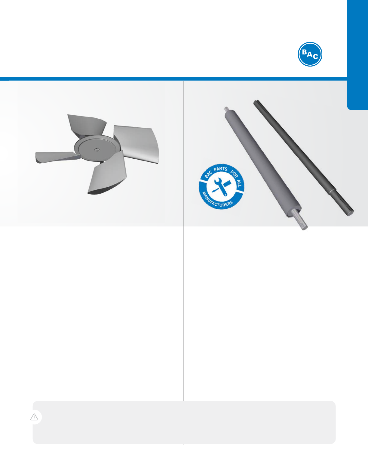
Axial Fans
› Standard fan is high-efficiency and low sound
› Rugged, aluminum construction for corrosion resistance and
extended life
› For further reduced sound levels, Low Sound Fans, Whisper
Quiet Fans, and sound attenuation are available
› Factory balanced for easy installation and vibration-free
operation
› Maintain thermal performance as originally certified by CTI
› Most fan kits include bushing and special length bolts
AVAILABILITY: Available in sizes from 24” to 156” diameter,
4 blades to 12 blades for economical and quiet operation.
Centrifugal Fans
› Centrifugal fans have inherently low sound characteristics
› Available in multiple materials of construction to meet
various operating conditions
› Engineered and rated by BAC for optimum performance
› Maintain thermal performance as originally certified by CTI
› Complete installation kit includes hardware, adhesive, and
clamps
AVAILABILITY: Available in 15”, 18”, 22”, and 30” diameters
for shafts 1-3/16” to 5” in diameter. Fits BAC and other
manufacturers’ products.
2 BALTIM ORE A IRC OIL COMPANY
FANS & DRIVES
BAC CAUTION TIP:
Hub clamp bolts should be tightened gradually to a torque of 30 ft/lbs. Tighten bolts evenly around the clamp so that gaps are equal.
Shafts
› Specially selected tubing materials ensure strength and
durability
› BAC shafts are precision manufactured for vibration-free
operation
› Epoxy-coated for corrosion resistance
› Journals are ground and polished for an accurate fit and
easy bearing and drive component installation
› Long keyways for multiple drive combinations
› Grooved flats for positive, secure set-screw installation
AVAILABILITY: Sizes from 1” to 2-15/16” diameter and 18” to
148” long. Many available with nickel plating or in stainless
steel for added corrosion resistance.
Whisper Quiet Fans
› Ultimate low sound solution
› Available for Series 3000, 1500, PT2, FXV, and CXVB units
› Reduces sound levels generated from the unit with
minimal impact on thermal performance
PARTS & MAINTENANC E G UIDE 3
FANS & DRIVES
FIND YOUR REPRESENTATIVE:
BaltimoreAircoil.com/repfinder
Or Call:
800.896.8497

FANS & DRIVES
Automatic Bearing Greaser
› Compatible with all BAC bearings and other non BAC bearings
› Lithium batteries are standard
› Positive displacement pump allows installations up to 20 feet away from bearings when
using single and multiple greaser kits
› Variable output and user-settable based on number of bearings, size and type of service
› Significant labor savings through less maintenance
› Multi-Point Automatic Bearing Greasers are now available in 250cc and 500cc
› Replacement grease packs and batteries are available from stock
4 BALTIM ORE A IRC OIL COMPANY
Don’t forget
to order
bearing greaser
refill packs!

Multi-Point Automatic Bearing Greaser
Forced Draft – Multiple Bearings per Greaser
Bearing
Quantity Size of Bearings Multi-Point Greaser Setting
2
1-11/16”
or smaller
250cc Multi-point kit 1 Year
4
1-11/16”
or smaller
500cc Multi-point kit 6 Month
2
Larger than
1-11/16”
250cc Multi-point kit
500cc Multi-point kit
6 Month
1 Year
Induced Draft – Multiple Bearings per Greaser
2
1-11/16”
or smaller
250cc Multi-point kit 1 Year
4
1-11/16”
or smaller
500cc Multi-point kit 6 Month
2
Larger than
1-11/16”
Smaller than 2-15/16”
250cc Multi-point kit
500cc Multi-point kit
6 Month
1 Year
4
Larger than
1-11/16”
Smaller than 2-15/16”
250cc Multi-point
500cc Multi-point
3 Month
6 Month
2 2-15/16” 500cc Multi-point 3 Month
Single Automatic Bearing Greaser
Forced Draft – One Greaser per Bearing
Bearing
Quantity
Size of
Bearings
Bearing
Greaser Setting
1
1-11/16”
or smaller
125cc 1 Year
1
Larger than
1-11/16”
125cc
250cc
6 Month
1 Year
Induced Draft – One Greaser per Bearing
1
1-11/16”
or smaller
125 cc 1 Year
1
Larger than
1-11/16”
Smaller than
2-15/16”
125cc
250cc
6 month
1 Year
1 2-15/16” 250cc 3 Month
FANS & DRIVES
PARTS & MAINTENANC E G UIDE 5

Induced Draft Bearings
› Rated with a minimum L
10
of 80,000 or more operating hours
› Industrial grade pillow block castings for extended life
› Exclusive BAC slinger/locking collar keeps water off the
bearing seals
› Double-lip seal to keep moisture from contaminating the
grease
› Complete installation kit includes all hardware, shims, and
instructions
AVAILABILITY: Sizes from 1 7/16” to 2 15/16” for all vertical shaft cooling
tower applications.
Forced Draft Bearings
› Rated for an average life of 200,000 operating hours
› Pre-packed with water resistant grease for
easy maintenance
› Split sleeve design bearings are available for easy
replacement
AVAILABILITY: Sizes from 1” to 2 3/16” in flange mount, sleeve, split sleeve,
and pillow block ball bearing configurations.
BAC MAINTENANCE TIP:
If replacing only the top fan shaft bearing on vertical shafts, the locking collar on the bottom fan shaft bearing must be loosened and
then retightened after the installation of the new top bearing. This is critical because, by design, the top bearing is intended
to handle the thrust load.
6 BALTIM ORE A IRC OIL COMPANY
FANS & DRIVES

Cast Iron Bushings and Sheaves
› Minimum 2.0 service factor
› Fine-grain, high-strength cast iron
› Factory balanced for smooth operation
› Bushing design minimizes fretting corrosion on the shaft,
which greatly eases removal when required
AVAILABILITY: Bushing styles for all standard drive components from 1” to 2
15/16” diameter. Cast iron sheaves for all drive combinations, 1 to 8 grooves.
Aluminum Sheaves
› Designed for use with all induced draft cooling towers
› Corrosion resistant aluminum alloy for operation in the moist
cooling tower environment
› Less corrosion means less wear on sheave grooves and
extended belt life
› Available for both driver and driven shafts
AVAILABILITY: From 2 groove to 8 groove, 3 3/5” to 50” diameter for all
induced draft applications.
BAC MAINTENANCE TIP:
See bushing torque requirements for Cast Iron and Aluminum Sheaves in the reference section on page 43.
Always replace
bushings and
bearings
together to
reduce downtime!
PARTS & MAINTENANC E G UIDE 7
FANS & DRIVES
FIND YOUR REPRESENTATIVE:
BaltimoreAircoil.com/repfinder
Or Call:
800.896.8497

Belts and Powerbands
› Engineered for evaporative cooling operations
› Rated for 150% of unit horsepower
› Neoprene, backed with reinforced polyester, specifically
designed for extended life
AVAILABILITY: Up to 8 grooves and 195” long in A groove,
B groove, and cogged configurations.
ENDURADRIVE™ Fan System
Retrofit Kit
› Complete kit with matching motor, VFD, fan, bushing and
upgraded 2 beam mechanical support
› 90% reduction in maintenance costs
› Up to 10% energy reduction vs standard gear drive system
› 100% reliability with the elimination of a power transmission
system
› Industry best 7 year motor warranty and 5 year limited VFD
warranty
AVAILABILITY: Horsepower ratings from 20 to 125 horsepower with mounting
and shaft dimensions to fit the Series 3000 Cooling Tower.
8 BALTIM ORE A IRC OIL COMPANY
FANS & DRIVES

BAC Gear Systems
› Meet AGMA and CTI standards to ensure reliability
› Constructed of high-strength cast iron for
low sound, vibration-free operation
› Gear drives are available for both BAC and other
manufacturers’ equipment (exact dimensional fit, no
modification required)
AVAILABILITY: Horsepower ratings from 7.5 to 100 horsepower with mounting
and shaft dimensions to fit virtually any make of cooling tower.
Gear Couplings
› No need for maintenance or lubrication
› Installation is quick and easy, and no special tools are needed
› Couplings absorb all types of misalignment caused by shock
or vibration
› Not affected by dirt or moisture
Composite Drive Shafts
› Composite shaft ships with 316 SST gear and motor
couplings and hardware
› Made from high-strength composite material that allows for
higher misalignment tolerance
› Corrosion resistant
› Lightweight, which reduces vibration and extends the life of
the shaft
BAC TECH TIP:
Prior to installing the couplings, it is important to clean the shaft of any lubricants or protective coatings, as well as remove any existing
burrs that may damage the coupling.
PARTS & MAINTENANC E G UIDE 9
FANS & DRIVES
FIND YOUR REPRESENTATIVE:
BaltimoreAircoil.com/repfinder
Or Call:
800.896.8497

Premium Efficient Motors
› Motors are engineered specifically for the rigors of cooling tower applications
› Made of high-grade FC-200 cast iron for maximum cooling and includes additional grounding plug
› Permanently sealed bearings never require lubrication and eliminate water contamination to the
bearing grease
› BAC Premium Efficiency Cooling Tower Duty Motors are covered by a 7 year warranty when the motor
space heater is wired according to the motor wiring diagram.
› IP55 rating for greater protection from water and particulate contaminants
Bearings – Permanently sealed
and lubricated bearings provide
maintenance free long life.
Umbrella Seal – Fits over V-ring slinger
to provide protection from water and other
contaminants.
Conduit Box – Fully
gasketed, cast iron conduit
box includes drain plugs, lead
separator gasket, and internal
epoxy coating.
Internal Epoxy Coating –
Entire interior of the motor is
coated with epoxy for maximum
moisture/corrosion resistance.
Drain Plugs – Located every 90 degrees and on
the face of each endshield. They are easy to open
and accommodate all mounting configurations.
THE ENDURADRIVE
TM
FAN SYSTEM RETROFIT KIT
Includes Factory Authorized Start Up
10 BALTIM ORE A IRC OIL COMPANY
FANS & DRIVES

Baltimore Aircoil Company’s ENDURADRIVE
™
Fan System is the most
durable engineered solution for your Series 3000 Cooling Tower!
BAC’s new ENDURADRIVE™ Fan
System retrofit kit gives you:
9
100% reliability on transmission components
versus a traditional gear drive system
9
90% reduction in maintenance costs
9
All while providing you the opportunity to increase
your energy savings by 10%
Please contact your local Representative for more
information at
www.BaltimoreAircoil.com/repfinder
or by calling 410.799.6200.
This system is available for retrofit on Series 3000
units manufactured between 1991 through today!
includes
KIT
THE ENDURADRIVE
TM
FAN SYSTEM RETROFIT KIT
Includes Factory Authorized Start Up
MOTOR AND
MATCHING VFD
FAN AND BUSHING
NEW 2-BEAM
ENDURADRIVE ME SUPPORT
WITH MOTOR BASE
SPOTLIGHT
PARTS & MAINTENANC E G UIDE 11

Spray Branches
› Constructed of corrosion resistant PVC
› Grommeted construction allows spray branches and nozzles
to be easily removed
Water Distribution Nozzles
› BAC 360™ Spray Nozzle, A, AA, and Pyramid Nozzles are
grommeted for easy inspection and removal
› XF nozzles are gravity flow and can easily be inspected and
replaced while unit is in operation
› Kits are available to install 360™ Spray Nozzles in other
manufacturers coil products
› Patented design for pressurized or gravity-feed systems
guarantees optimum thermal performance
› Large orifice means non-clogging performance for effective
wetting of the heat-transfer surface
› Multiple sizes are available to accommodate
all system flow rates
AVAILABILITY: 1/4” through 1 1/8” orifice for properly
metered flow.
A or AA Counterflow Nozzle
used on open cooling towers
BAC 360™ Spray Nozzle
used on closed circuit
cooling towers and
evaporative condensers
XF Crossflow Nozzle used
on open cooling towers
BAC MAINTENANCE TIP:
Always check spray nozzles when inspecting evaporative cooling equipment as poor spray patterns will negatively effect unit performance.
BAC’s Pyramid nozzles
are used in IPC, IMT, and
other manufacturers’ field
erected units
12 BALTIM ORE A IRC OIL COMPANY
WATER DISTRIBUTION

Spray Pumps
› Cast iron, bronze-fitted construction with mechanical seal
means pumps are industrial quality for a long, trouble-free
life
› Impeller and trims have been selected for difficult high-flow,
low-head requirements, assuring complete coil wetting to
reduce scale and provide maximum thermal capacity
› Supplied with vented seal housing to prevent air binding and
to provide a sump bleed connection
› Mechanical seal is constructed with a carbon rotating
element and a ceramic stationary element with stainless
steel hardware for a long, leak-free life
AVAILABILITY: High efficiency, high flow/low head pumps 1/3 through 10
horsepower and 1 1/2” through 4” discharge.
Pump Seal Kits
› Replacement TEFC pump motors are designed for outdoor
application
› Complete seal kits available from stock
› Shaft sleeves are available for pumps 1.5 hp and larger
BAC TECH TIP:
The pump is supplied with a bleed line and valve connected to the seal vent. This valve can be set to provide the proper bleed rate to
minimize impurities in the basin water.
Even if the basin bleed is accomplished by other methods, always leave the valve slightly cracked to prevent air binding in the pump.
PARTS & MAINTENANC E G UIDE 13
FIND YOUR REPRESENTATIVE:
BaltimoreAircoil.com/repfinder
Or Call:
800.896.8497
WATER DISTRIBUTION

Float Valves
› Rubber seal disc assures a positive shut-off to prevent
water waste
› Reliable stainless steel linkage in all kits
AVAILABILITY: 1/2” to 2” valves for all applications.
Float Balls
› Heavy-duty polypropylene construction resists cracking
› Foam-filled for structural rigidity and additional buoyancy
› Available in many sizes and configurations to ensure
positive shutoff
AVAILABILITY: 4 1/2” to 8” diameter and 10” pancake style
for all applications.
BAC CAUTION TIP:
Many commercially available float balls are hollow with no foam filling and are not suitable for the rigors of evaporative cooling
equipment. While operating, the inside of your equipment can resemble a hurricane with high winds and extreme temperature swings.
Without the added structural rigidity from the foam filling, the float ball may easily crack, allowing the float to fill with water, which
will cause the system to run improperly. Do not exceed 50 psi inlet water pressure to the float valve.
BAC TECH TIP:
Upon start-up, fill the tower to approximately 1/2” below the overflow level before starting the unit. This will provide enough water to
fill the rest of the system without draining the tower on start-up. After the system is running, adjust the water level as shown in your
Operation and Maintenance Manual. Monitor the operating level for the first 24 hours of operation to make sure it is set properly.
PVC Float Valve
Brass Float Valve
14 BALTIM ORE A IRC OIL COMPANY
WATER DISTRIBUTION
14 BALTIM ORE A IRC OIL COMPANY

Electric Water Level Control
› Universal mounting system fits any tower
› Completely sealed and waterproof
› Located inside the tower so no heat tracing is required
› 6 second time delay prevents short-cycling
› Plastic sheath on probes and stilling chamber prevents
false-cycling
› Requires 110 volt solenoid valve for operation
› Equipped with trouble shooting LED to diagnose water and
probe conditions
AVAILABILITY: 3-probe through 6-probe models for on/off, low water cut-out,
low water alarm, high water cut-out, and/or high water alarm.
Solenoid Valves
› Forged brass body for durability and high-pressure
applications
› Watertight electrical enclosure for outdoor use
› Slow-closing feature minimizes water-hammer on shut-off
› Valves are sized for a water pressure between 15 and 50 psig
at the valve inlet
AVAILABILITY: 3/8” to 2” with 110 volt normally closed holding coil.
BAC TECH TIP:
LED error codes can be found in the Universal Electric Water Level Control Installation, Operation & Maintenance Manual on BAC’s
website, www.BaltimoreAircoil.com.
PARTS & MAINTENANC E G UIDE 15
FIND YOUR REPRESENTATIVE:
BaltimoreAircoil.com/repfinder
Or Call:
800.896.8497
WATER DISTRIBUTION

Inlet Strainers
› Single point inlet provides automatic flow-balancing to both
hot water basins
› Inlet strainer protects water distribution nozzles from debris,
eliminating the need for a separate system strainer
› Large free-area inlet strainer minimizes pumping head
› Inlet strainer is easy to remove and clean
Series 3000 Cooling Towers built in 1991 through 2007 were equipped
with inlet strainers located in the BALANCE CLEAN
®
Chamber. The
BALANCE CLEAN
®
Chamber provides a single-point piping connection and
automatically balances the flow to both hot water basins. Contact your local
BAC Representative for replacement inlet strainers and options, such as winter
operation bleed down valves, that prevent freeze-up when the tower is shut
down.
Suction Strainers
› 3/16” strainer perforations help keep the system clean
› Strainer perforations are spaced to provide maximum strainer
free area for low pump suction losses
› Anti-cavitation design prevents air from reaching the system
pump
BAC offers many styles of suction strainers and suction hoods for just about
any application. Proper strainer design is critical to the total system operation.
It provides protection for the pump and keeps debris out of the condenser water
loop. BAC strainers are designed to offer optimum system protection while still
providing a full 50% free area to allow efficient system pump operation. Also
important, the anti-cavitation design is built into all BAC strainers. This keeps
air from entering the piping that would cause pump cavitation.
Inlet strainer
inspection for
Series 1500
Inlet strainer
inspection for
Series 3000
16 BALTIM ORE A IRC OIL COMPANY
WATER DISTRIBUTION

Combined Inlet Shields
› Available for the Series 3000E, Series 1500E, PT2, PF2, PFi,
PC2, PCC, FXV, FXV3, CXVT and CXVB units
› Prevent algae growth in the cold water basin
› Eliminate water splash out
› Prevent debris from entering the cold water basin
› Inlet shield is easy to remove and clean
› Separate from the fill and removable to allow easy access for
inspection of the air/water interface at the air inlet side of the
equipment
› Also available on the FXV and CXVB for installation above the
spray distribution system
Air Intake Louvers
› Wide spaced louvers reduce the potential for scale build-up
and damaging ice formations at the air/water interface by
providing an easy visual inspection from the outside of the
unit into the fill
› Standard air intake louvers are constructed of corrosion and
UV-resistant fiberglass reinforced polyester (FRP)
› Galvanized and stainless steel are available
PARTS & MAINTENANC E G UIDE 17
FIND YOUR REPRESENTATIVE:
BaltimoreAircoil.com/repfinder
Or Call:
800.896.8497
WATER DISTRIBUTION

Basin Heaters
› UL and CSA rated
› Durable copper heating elements for long life
› 2” MPT connection is easy to retrofit into any cooling tower
AVAILABILITY: 2 – 24 kW ratings, 50 watts/in
2
watt density
200, 230, 460, and 575 volt.
BAC stocks a complete line of immersion heaters to prevent cold water basin
freeze-up during winter weather. These heaters are selected for cooling tower
duty and are constructed with copper heating elements rated at 50 watt/in
2
with a 2” MPT brass connection and conduit box rated NEMA 4. Heaters are
suitable for use in all makes of evaporative cooling equipment.
Basin Heater Controls
› UL and CSA rated
› BAC thermostats and low water cutouts are designed to
ensure long life and proper operation
› Individual components or complete kits available
› Standard heater control panel consists of:
– S ingle probe to sense both water
temperature and water level
– Contactor(s)
– 24 Volt control circuit transformer
– NEMA 4 Enclosure
– UL Listed
18 BALTIM ORE A IRC OIL COMPANY
CONTROLS

Float Switch
› Single-pole, double throw, liquid level float switch
› Designed to maintain a liquid level in the cold water basin
› When liquid level rises above or falls below a certain point,
the switch will close one circuit and open a second
Mechanical
Vibration
Cutout Switch
Electronic
Vibration
Cutout Switch
Vibration Cutout Switches
› Protect your tower from damage resulting from excessive
vibration
› Mechanical or electronic switches are available with multiple
options for alarms and reset
› Electronic switches are compatible with building
management systems
BAC MAINTENANCE TIP:
Test vibration switches during seasonal start-ups to ensure proper operation.
See pages 38 & 39 in the Reference Section for Basic Operation and Troubleshooting of the Vibration Cutout Switches or contact your local
BAC Representative for more information.
PARTS & MAINTENANC E G UIDE 19
FIND YOUR REPRESENTATIVE:
BaltimoreAircoil.com/repfinder
Or Call:
800.896.8497
CONTROLS

› VFD Only: Includes a single VFD in a
weather-resistant enclosure sized to control
all fan motors on the unit
› Total Controls Package: Includes the
VFD Only PLUS sequencing and accessory
contactors
Benefits of BAC
Refrigeration Controls:
› Controls specifically designed for
industrial refrigeration applications
› Single point wiring (optional)
› UL/cUL listed
› All panel enclosures are NEMA 3R as standard
› Easy installation
› Total controls package
[1]
Communication Protocols limited to Modbus, Lonworks, Johnson N2, BACNet, and Siemens APOGEE.
Fan Starter(s)
Spray Pump Starter
Basin Heater
(s)
Vibration Cutout Switch Interface(s)
Electric Water Level Control Contactor(s)
Communication Card
[1]
Sequencing Logic
Weather-Resistant Enclosure
Start-Up
(Option)
Pressure Controller
9
9
9
9
9
9
9
9
9
9
9
VFD VFD
OPTIONAL OPTIONAL
VFD ONLY
TOTAL CONTROLS
PACKAGE
Modbus-standard Modbus-standard
CONTROLS
BAC Refrigeration Controls
20 BALTIM ORE A IRC OIL COMPANY

Performance
› Increase performance
and efficiency
› Restore lost performance
Ease of Maintenance
› Safety and access items
› Serviceability upgrades
Operational Items
› Capacity control and redundancy
› Controls
Sound
› Reduced sound levels
Retrofit and Rejuvenate Your Equipment
BAC offers a variety of retrofit kits and accessories to rejuvenate or maximize the performance
of your evaporative cooling equipment. Whether your unit appears to be on its last leg or brand
new, BAC parts and retrofit kits are available to bring it back to life or add features to meet the
needs of your projects.
RETROFITS
[1]
Communication Protocols limited to Modbus, Lonworks, Johnson N2, BACNet, and Siemens APOGEE.
PARTS & MAINTENANC E G UIDE 21

ENERGY SAVING RETROFITS
22 BALTIM ORE A IRC OIL COMPANY
Retrofit Opportunities
Water Distribution
Mechanical Drive Components
Fill
BAC VFD (Variable Frequency Drive)
1
2
3
4
A 2°F Decrease in Leaving Water Temperature Saves 6% in Electricity Costs
On average the HVAC system uses 25% of a building’s electricity. The slightest increase in
cooling tower leaving water temperature will result in significantly higher energy costs.
1
Annual Cooling Tower Efficiency Savings
2
$5,306
$10,612
$15,918
1˚F 2˚F 3˚F
Cooling Tower Leaving Water Temperature Decrease
› Note 1: U.S. Energy Information Administration (EIA)
› Note 2: Savings are based on the energy costs for a 500 ton centrifugal chiller, 0.68 kW/ton chiller efficiency at full load, $0.12/kWh energy cost, $25/kW per
month, 80% ratchet demand charge, and 2,000 equivalent full load hours of operation.
SPOTLIGHT

ENERGY SAVING RETROFITS
Replace Nozzles
Broken or clogged nozzles cause uneven water distribution
over the fill, scale build-up, and decreased capacity.
Upgrade or Replace Drive Components
For increased building heat loads, BAC’s drive upgrade kits
will increase the capacity of your cooling tower.
To maintain the peak performance of your cooling tower,
replace your motors, drive sheaves, drive bushings and belts
with BAC Factory Authorized Parts.
Install New Fill
Replace scaled or clogged fill with BAC’s replacement fill
kits that are designed with state-of-the-art fill technology to
restore or increase the capacity of your cooling tower.
Install a VFD
Adding a Variable Frequency Drive will provide a more efficient
method of operating your cooling tower while extending the life
of the motor and mechanical drive system.
Contact your local BAC Representative for a free unit inspection
and consultation on Energy Saving Retrofits.
1
2
3
4
2% to 3% Energy Savings
3% to 7% Energy Savings
7% to 10% Energy Savings
30% to 40% Energy Savings
1
o
F Decrease in Leaving
Water Temperature
1-2
o
F Decrease in Leaving
Water Temperature
2
o
F Decrease in Leaving
Water Temperature
Pay Back Period: Less Than 1 Year
Pay Back Period: Less Than 1 Year
Pay Back Period: Less Than 1 Year
Pay Back Period: 2-3 Years
PARTS & MAINTENANC E G UIDE 23
SPOTLIGHT

BACross
®
Replacement Fill Kits
For FXT, Series 1500, Series 3000, FXV, FXV3,
CXV and CXVB
› Maintains thermal performance as originally certified by CTI
› Available in standard PVC for normal temperature
applications or CPVC for high temperature applications
VersaCross
®
Replacement
Fill Kits
› Outstanding thermal performance will meet or exceed the
performance of any OEM fill
› Fits most crossflow towers
› Quick and easy field installation saves labor
› Nested shipment requires smallest fill staging area and low
shipping costs
› Model-specific kits contain everything needed for an efficient
installation, including detailed instructions, supports,
hardware, and fill
› 2-week standard lead time
BAC TECH TIP:
Block fill is not recommended for use in BAC’s crossflow cooling products and may decrease the thermal capacity of the unit by 10%.
24 BALTIM ORE A IRC OIL COMPANY
RETROFITS
PROJECT SPOTLIGHT
BACount
®
Replacement
Fill Kits
For Series V Counterflow products
› Maintains the thermal performance as originally certified by
CTI
› Single-source responsibility, providing quality materials and
a guaranteed fit
› Available in standard PVC or CPVC for high temperature
applications
› Maintains 3/4” spacing to minimize fouling
BAC Pak™ Replacement
Fill Kits
For PT2 Counterflow products
› For use in counterflow and induced draft counterflow cooling
towers
› Pre-engineered kits to fit specific counterflow, and induced
draft counterflow cooling towers
› Easy to install
› All hardware and supports included
› Available in standard PVC or HPVC for high temperature
applications
BAC MAINTENANCE TIP:
Maintain or increase thermal capacity in all BAC counterflow cooling towers with BACount
®
Fill Kits. They offer the same
efficient heat transfer surface as currently supplied in new BAC towers, in an easy-to-install bundled configuration.
PARTS & MAINTENANC E G UIDE 25
RETROFITS

VersaCross
®
Replacement Fill improves thermal performance of the original
fill by an average of 7.3% and 10% on other Manufacturers’ block fill.
Customer Benefits
› Only replacement hanging fill on the market
› Designed to meet or exceed original performance specifications
› Lower shipping costs versus block fill
› Nested shipments require smaller staging areas
› Fill fits in most Class A freight elevators
› Shorter lead time than block fill
Integrated Custom Features
› Includes integral louvers and drift eliminators to eliminate splashout and drift
› Formed from 15 mil self-extinguishing PVC
› Fits most BAC crossflow towers
› Suitable for maximum entering water temperature of 130˚F
Custom Installation Kit
s
Hanging PVC VersaCross
®
Fill
s
Fill hangers and supports
s
D
etailed instructions
s
Complete Hardware
26 BALTIM ORE A IRC OIL COMPANY
VERSACROSS
®
REPLACEMENT FILL
SPOTLIGHT

Internal and External Service Platforms,
Catwalks, and Walkways
› OSHA compliant
› Simplify maintenance
› Available in complete engineered kits
› Keep feet dry
› External service platforms allow for easy access to hot water basins or spray
distribution systems
› Internal walkways and internal platforms and ladders provide easy access to
drive components
BAC MAINTENANCE TIP:
Newer unit designs do not require routine maintenance on the fan deck. Louver face platforms allow easy access and
inspection of the water distribution area while the unit is in operation.
VERSACROSS
®
REPLACEMENT FILL
PARTS & MAINTENANC E G UIDE 27
FIND YOUR REPRESENTATIVE:
BaltimoreAircoil.com/repfinder
Or Call:
800.896.8497
FANS & DRIVES
RETROFITS
FANS & DRIVES
RETROFITS

BAC MAINTENANCE TIP:
Ladders and handrails are available for access to the top of the equipment. If the end-user elects to use this alternative, the
addition to the installation will make routine maintenance easier, and improve overall performance and unit life expectancy.
All BAC safety and access retrofit packages meet OSHA requirements.
Pre-assembled Platforms
› OSHA compliant
› Increases the ease of maintenance
› Available on Series 3000, Series 1500, PC2, PT2, FXV, FXV3, PF2, CXVB, CXVT and VCA models
› Ships in modules for quick and easy installation
› Three configurations available for the VCA (flush, offset, and full perimeter)
28 BALTIM ORE A IRC OIL COMPANY
RETROFITS

Add Redundancy and Capacity Control
› ENERGY-MISER
®
/BALTIGUARD™ Fan System maximizes up-time
› Saves energy
› Maintains required performance for approximately 85% of the year, using only 1/3 of the full-load HP
› Utilizes standard, cooling tower duty motors for easy replacement: no need for two-speed or special
motors required
Redundancy – A simple solution to add redundancy is the ENERGY-MISER
®
/BALTIGUARD™ Fan System. This option adds a second
fan motor to the drive system. This second motor is usually sized at approximately 1/3 of the main motor horsepower. This allows the
smaller motor to operate around 85% of the year, while the larger main motor is only required on the hottest of days. Unlike a two-
speed motor, this causes less wear and tear on the fan motors and provides redundancy in case of a motor failure. In addition, the
single-speed motors are available “off the shelf” from BAC.
Capacity Control – The ENERGY-MISER
®
/BALTIGUARD™
Fan System also provides capacity control similar to a two-speed motor.
Another capacity control option is adding a VFD to control the motor speed. If you are thinking of converting to a VFD system, BAC can
supply the VFD and a fan motor built for that application; see page 20.
BAC TECH TIP:
The ENERGY-MISER
®
/BALTIGUARD™ Fan System utilizes the control and switch-gear of a two-speed, two-winding motor while
providing the security and economy of a redundant motor. You always have a motor, even if one motor fails.
PARTS & MAINTENANC E G UIDE 29
FIND YOUR REPRESENTATIVE:
BaltimoreAircoil.com/repfinder
Or Call:
800.896.8497
FANS & DRIVES
RETROFITS
FANS & DRIVES
RETROFITS

Aluminum Sheave
and Bushing Kits
› Complete with bushing and special bushing bolts
› Special torque requirements and installation techniques
included with kit instructions
› Corrosion resistant aluminum allows for operation in the
moist cooling tower environment
› Available exclusively from BAC
› Designed for the specific power transmission required by the
motor and fan application
Aluminum Fan
and Bushing Kits
› Complete with bushing and special bushing bolts
› Special torque requirements and installation techniques
included with kit instructions
› Corrosion resistant aluminum allows for operation in the
moist cooling tower environment
› Available exclusively from BAC
› Designed for the specific airflow requirements
of the cooling tower
BAC MAINTENANCE TIP:
Proper installation of aluminum sheaves also requires the bolts to be tightened to the specific torque values as shown on
page 43. The chart also indicates the proper bushing type for each sheave.
30 BALTIM ORE A IRC OIL COMPANY
RETROFITS

Large Orifice Spray
Distribution Retrofits
› Large orifice grommeted nozzles can easily be retrofitted in
BAC’s older designed products and in other manufacturers’
units
› Grommetted installation makes spray branches and nozzles
easy to remove, clean, and replace
› Non-clogging, large-orifice nozzles
› Available in pre-engineered kits for your equipment
Low Sound Alternatives
› Intake and discharge attenuation packages are available
› Fully factory-tested and rated
› Can be used in conjunction with low sound fan options
› Available on both counterflow and crossflow products
BAC TECH TIPS:
Proper spray water distribution is important to the long-term efficiency of your cooling tower. A fully wetted coil or fill surface
will resist scaling and dirt build-up while maintaining peak thermal efficiencies.
Many replacement towers utilize axial fans instead of centrifugal fans. Axial fans produce higher sound levels than centrifugal
fans. Contact your local BAC Representative for sound ratings and sound solutions. Consult the BAC website,
www.BaltimoreAircoil.com, for more information on sound.
PARTS & MAINTENANC E G UIDE 31
FIND YOUR REPRESENTATIVE:
BaltimoreAircoil.com/repfinder
Or Call:
800.896.8497
FANS & DRIVES
RETROFITS

Drift Eliminators
› Engineered for maximum performance and corrosion
resistance
› Available in PVC, thermosetting hybrid polymer, galvanized or
stainless steel construction
› Complete kits available
› Helps conserve water
Replacement Coils
BAC offers a large selection of coil configuration options
to fulfill any thermal and pressure drop requirements for
both BAC and other manufacturers’ evaporative cooling
equipment.
› Industrial grade construction, ASME B31.5 compliant
› Standard patented serpentine coils are 16 gauge and HDGAF,
minimizing scale and fouling potential
› Materials of construction provide compatibility with virtually
any refrigeration, air conditioning, or process fluid system
› Construction options include:
– ASME “U” construction when conditions require
pressure vessel compliance
– Extended surface finned coils for plume reduction and
water savings
– Cleanable tubes or cleanable headers for dirty fluid
application
– Stainless Steel coils
– 14 gauge coils are also available
› CRN coils available for Canadian installations
32 BALTIM ORE A IRC OIL COMPANY
RETROFITS

Parts for all Evaporative Cooling Equipment
› BAC offers a full range of replacement products for other manufacturers units such as:
– Replacement coil and casing sections
– Motors
– Automatic Bearing Greasers
– Drive components including fans, shafts,
bearings, sheaves, and belts
– Fill and eliminators
– Spray distribution retrofit kits
– BAC Controls
– Heaters and heater controls
– Electric water level and make-up controls
– Vibration cutout switches
– Composite drive shafts
– Gears for all factory assembled cooling towers
› All BAC Parts are designed and manufactured
to meet BAC’s original quality standards
and are backed by a 1-year warranty
› Motors have a 5-year warranty, 7-year when installed with space heater
PARTS & MAINTENANC E G UIDE 33
FIND YOUR REPRESENTATIVE:
BaltimoreAircoil.com/repfinder
Or Call:
800.896.8497
FANS & DRIVESFANS & DRIVES
RETROFITS

Velocity Recovery Stacks
› Available on most Series 3000 Cooling Towers
› Increase thermal performance
› Maintain tower footprint
› Maintain existing CTI certification on Series 3000A and
3000C Cooling Towers
Drive System Upgrade
› Comprehensive option for upgrading cooling capacity
› Larger motor
› New sheave and belt configuration
› New fan and fan shafts available
Remember to specify
the ENDURADRIVE™
Fan System retrofit kit.
Details on page 8.
34 BALTIM ORE A IRC OIL COMPANY
RETROFITS

Davit Systems
› Facilitates motor replacement
› Removal system includes davit arm(s) and access
panels on the side opposite of the air inlet face on FXV
and CVXB only
› Series 3000, PT2, and PC2 davit allows for quick and
easy motor removal
› Davit on Series 3000 can be easily moved from cell to
cell as it simply slides and locks into socket
BAC Cooling Tower
Service Kits
› Psychrometer
› Infrared thermometer
› Conductivity meter
› A/C current clamp
› pH meter
› Heavy-duty, waterproof flashlight
› Handheld digital anemometer
› Megger
®
brand insulation tester
› Tool bag
AVAILABILITY: This kit contains measuring instruments
to cover a full range of service needs, including temperature,
air flow, electrical parameters, and water quality
measurements.
PARTS & MAINTENANC E G UIDE 35
FIND YOUR REPRESENTATIVE:
BaltimoreAircoil.com/repfinder
Or Call:
800.896.8497
FANS & DRIVESFANS & DRIVES
RETROFITS

Maintenance Checklist for:
Cooling Towers, Closed Circuit Cooling Towers, and Evaporative Condensers
[1]
Inspect and clean as necessary: Start-Up Monthly Quarterly Annually Shutdown
Inspect general condition of the unit
[2]
and check unit for unusual noise or vibration
Inspect cold water basin
Flush water distribution system/inspect spray nozzles
Drain basin and piping
Inspect air inlet louvers/combined inlet shields
Check and adjust water level in basins
Check operation of make-up valve
Check and adjust bleed rate
Inspect unit finish
Mechanical equipment system: Start-Up Monthly Quarterly Annually Shutdown
Check belt condition
Adjust belt tension
[3]
Lubricate fan shaft bearings
Lubricate motor base adjusting screw
Check and lubricate optional gear drive
See product specific O&M Manual for detailed instructions and schedule
Check drive alignment
Check motor voltage and current
Clean fan motor exterior
Check fan motor for proper rotation
Check general condition of the fan
Check and unplug fan drain holes (hollow blade fans)
Check fan for uniform pitch
Check fan for rotation without obstruction
Check and recoat steel shafts with RUST VETO
®
NOTES:
1. Consult your product specific O&M Manual before conducting maintenance on the unit. Recommended service intervals are the minimum for
typical installations. Different environmental conditions may dictate more frequent servicing.
2. When operating in ambient temperatures below freezing, the unit should be inspected more frequently. Refer to the “Cold Weather Operation”
section of the Operation and Maintenance Manual for more details.
3. Tension on new belts must be readjusted after the first 24 hours of operation and quarterly, thereafter.
WARNING: Do not perform any service on or near the fans, motors, and drives, or inside the unit without first ensuring that the fans and pumps are
disconnected, locked out, and tagged out.
36 BALTIM ORE A IRC OIL COMPANY

Basic Recommended Spare Parts
s Bearing set
s Float valve
s Float ball
s Solenoid valve (if unit is equipped with electric water
level control)
s Powerband or set of belts
s Spray nozzle kit with grommets
s Basin heater and low water cut out
s Door gasket
s Strainer (inlet and suction)
s Fan and sheave bushings
s Pump seal and gasket kit for coil products
s Automatic bearing greaser refill kit
Parts to Consider if Extended
Downtime is a Concern
s Spray pump for coil products
s Axial or centrifugal fans
s Fan shaft
s Sheave set
s Fan motor
s Electric water level control
BAC Factory Authorized Parts are manufactured to meet rigorous cooling tower duty specifications and are guaranteed to fit your unit and perform as
original equipment.
BAC Factory Authorized Parts can be ordered through your local BAC Representative or online at www.CoolingTowerWorld.com. Most BAC Representatives maintain
a local inventory of commonly used parts. For a free unit inspection, call your local BAC Representative today.
Even with BAC’s fast delivery capability, it is still recommended that certain essential, emergency repair parts be maintained in your inventory to minimize any
potential downtime.
Recommended Spare Parts
PARTS & MAINTENANC E G UIDE 37
REFERENCE

A. Checking the Installation
The electronic VCOS is the standard switch used by BAC. This switch is rated
for 5 amps continuous duty and for in-rush of 25 amps for 1 sec
or 50 amps for 16 msec. This is ideal when wiring the switch to a motor
starter system, since the bigger the motor, the higher the current on the starter.
A computerized Building Management System (BMS) works on a very low
current draw. Therefore, some additional measures must be taken when
wiring the VCOS to a BMS. For the VCOS to turn on and stay on, it needs to
be connected to a load that draws a minimum of 50mA. Without this current
draw, the switch may not stay closed or “pulled in”. In this case, a 2000-ohm,
10-watt resistor can be wired in parallel with the BMS input. An interposing
relay (SPDT, class C) can also be installed to draw the 50mA.
B. Reset and Lockout Circuits
BAC supplies the switch prewired with 7’ of 20 Ga., UV resistant shielded
cable. When this cable is removed and other wiring supplied to the switch by
the customer, make sure that the reset and lockout terminals (terminals 5, 6,
and 7) are shielded from the rest of the wires.
The switch comes from the factory with terminals 5 and 6 connected together
with a wire nut, which enables the local reset circuit. This means that when the
switch trips, the pushbutton on the side of the switch must be used to reset it.
If this wire nut is removed, and nothing is connected to terminals 5 and 6, the
switch is not latched. This means that when the switch trips due to excessive
vibration, the switch will automatically reset itself once the vibration level
drops. This will cause the fans to restart automatically.
When a remote reset is desired, terminals 5 and 6 are wired to a pushbutton at
the desired remote location. Be sure to use shielded cable.
C. Mounting
The vibration switch must be mounted rigidly to the unit, ensuring that the
mounting brackets are stiffened to avoid any resonant builds that could cause
nuisance trips. Contact your local BAC Representative with any questions
regarding the installation of the VCOS for your specific equipment model.
D. Testing Basic Operation
The switch can be bench-tested or tested after it is mounted on the unit. For
safety reasons, the cooling system must be off during testing. Follow these
easy steps to test the proper operation of the vibration switch.
Testing time delay
The time delay is field adjustable from 1 to 15 seconds. It is set at the factory
to approximately 3 seconds.
a. Connect 110 or 220 volts to terminals 1 and 2 as per the appropriate wiring
diagram. Contact your local BAC Representative if you do not have this
diagram.
b. Jumper terminals 1 and 3 together.
c. Connect a 25-watt light bulb to terminals 2 and 4.
d. Since the switch comes from the factory with the slide switch in the N/C
position (see wiring diagram for the slide switch location), the light bulb
should turn on immediately. Set slide switch to the N/O position. The
light bulb should turn off. This assures that the triac relay is operating
properly.
e. Return the slide switch to the N/C position.
f. Turn the set point control knob counterclockwise to the test position. The LED
above the knob should turn on immediately. After approximately 3 seconds,
the triac changes state and the light bulb should turn off.
g. Return the set point control knob to the normal setting (0.45 in/sec).
h. If the switch is wired for local reset (5 and 6 wired together), depress the
pushbutton on the side of the vibration switch to return it to the non-alarm
condition.
i. If there is no connection across terminals 5 and 6, the switch will
automatically reset to the non-alarm condition.
j. To increase or decrease the time delay, turn the adjustment screw that
is located directly below the set point control knob. One full clockwise
turn increases the time delay by approximately 1/2 a second. One full
counterclockwise turn decreases the time delay by approximately 1/2 a
second.
If the vibration switch fails in any of the above steps, the switch should
be returned to the factory for repair or replacement. Contact the local BAC
Representative for more information.
Basic Operation and Troubleshooting of
BAC Electronic Vibration Cutout Switches (VCOS)
38 BALTIM ORE A IRC OIL COMPANY

FIND YOUR REPRESENTATIVE:
BaltimoreAircoil.com/repfinder
Or Call:
800.896.8497
BAC Mechanical Vibration
Cutout Switches (VCOS)
a. The vibration setpoint adjustment is accessible externally. Turning the
setpoint adjustment clockwise (CW) increases the vibration setpoint.
b. When the switch is shipped from the factory, the setpoint adjustment is set
to 2g when installed in the vertical position and 1g when installed in the
horizontal position (with reference to the setpoint adjustment shaft).
c. To check factory calibration, place the unmounted unit in your hand and
rotate per Diagram D. The switch(es) should activate at dead bottom
position. If necessary, adjust setpoint using setpoint adjustment screw.
d. To preset switch at other than factory setpoint, start with step three (3) and
then rotate adjustment screw 1/8 turn per g until you reach the required set
point.
e. To adjust setpoint when installed on the machine, mount and wire the unit.
Reset the switch by depressing the reset plunger and start the machine.
When the machine has reached full speed, slowly turn the vibration
setpoint adjustment counter clockwise until the switch tips. Then turn the
adjustment clockwise a small amount (approx. 1/8 turn). Try to reset the
switch; if the switch does not reset, turn another 1/8 turn clockwise and
repeat in increments of 1/8 turn until you are able to reset the switch. Reset
the switch and restart the machine to determine whether the machine
starting roughness will cause the switch to trip, in which case it may be
necessary to increase the setpoint.
Diagram D
Typical Installation Diagram
PARTS & MAINTENANC E G UIDE 39
REFERENCE

Fan Shaft Bearing Maintenance
Ball Bearings:
Seasonal shutdown and start-up:
When shutting your unit down for an extended period and before starting up after an extended shutdown, always purge the fan shaft bearings with new grease.
Lubrication Schedule:
s Induced draft products – Lubricate the bearings at least every three months.
s Forced draft products – Lubricate the bearings every 2000 hours of operation or every six months, whichever occurs first.
Greasing:
Bearings should only be lubricated with a hand grease gun or the automatic bearing greaser. When lubricating, purge the old grease from the bearing by gradually
adding grease until a bead of new grease appears at the bearing seal.
Type of Grease:
Only use one of the following greases, as they are compatible with the grease installed at the factory:
s Citgo Polyurea MP2™
s Conoco Polyurea 2™
s Exxon Polyurex
®
EM
s Exxon Unirex N™
s Mobilgrease
®
AW2
s Shell Alvania RL3™
s SKF LGHP2™
s Unocal 76 Unolife Grease™
Sleeve Bearings:
Start-up:
Prior to start-up and during the first week of operation, the bearing oil cup must be refilled with an industrial-type mineral oil to saturate the wick in the bearing
reservoir. After the initial start-up, fill the bearing oil cup every 1000 operating hours or every six months.
Type of Oil:
s 0ºF to 110ºF - BAC #582628P1, normal temperature range
s -25ºF to 30ºF - BAC #582627P1, low temperature range
BAC CAUTION TIP:
Sleeve Bearings: Do not use oils containing detergents. Detergent oils will remove the graphite in the bearing sleeve and cause
bearing failure.
Ball Bearings: Do not use high pressure grease guns, as they may rupture the bearing seals.
40 BALTIM ORE A IRC OIL COMPANY

FIND YOUR REPRESENTATIVE:
BaltimoreAircoil.com/repfinder
Or Call:
800.896.8497
Belt Tensioning
After initial tower start-up or the installation of a new belt, the belt tension
must be readjusted after the first 24 hours of operation. The condition of the
belt and belt tension should then be checked and adjusted quarterly.
To check the belt tension, place a straight edge along the belt from sheave to
sheave or, alternatively, use a tape measure as shown.
Apply a moderate force by hand (approximately 40 lbs) evenly across the
width of the belt in the center of the span between the two sheaves. If the belt
deflects between 1/4" and 3/8" as shown, the belt is adequately tensioned.
Sheave Alignment
As with proper belt tensioning, good sheave alignment will result in both
maximum performance and maximum belt life. Therefore sheave alignment
should be checked annually.
To check alignment, place a straight edge across the driver and driven sheaves
as shown in the figure for standard drive systems or the figure for the Energy-
Miser
®
/BALTIGUARD™ Fan System.
When the drives are properly aligned, the straight edge will contact all points
as indicated. There should be no more than 1/16" deviation from four-point
contact.
If realignment is necessary, loosen the motor sheave and align it with the fan
sheave and be sure to allow approximately 1/4" for draw-up as the bushing
screws are retightened.
Standard Drives
BALTIGUARD™/BALTIGUARD PLUS™
Fan System
PARTS & MAINTENANC E G UIDE 41
REFERENCE

Aluminum Fan & Bushing Installation Instructions
Bushing Installation Instructions:
1. Failure to follow these instructions may result in a cracked hub.
2. Do not use “Never Seize” or any lubricants on the bolts, bushings or shaft.
3. Do not attempt to bottom out the bushing in the aluminum fan hub. After proper bolt torque is applied, there should be a gap between the
bushing flange and fan hub.
4. Use the longest bolts provided with the bushing kit.
5. Wipe the shaft, bushing bore, bushing taper, and fan hub bore with a cleaning solvent to remove any dirt and oil.
6. Tighten each bolt a little at a time so that the bushing draws evenly into the fan hub without cocking to one side or the other. Torque the bolts as specified on the
chart above. Rotate the shaft to verify that it does not wobble.
CAUTION: READ COMPLETE INSTRUCTIONS BEFORE PROCEEDING:
Fan Type Product Type Bushing Type Bolt Torque (FT-LBS)
A FXT H 8
A VCA P 16
A VCA Q 29
B FXV and CXV Q 29
C PT2, Series 3000, Series 1500, FXV3 and CXVB, PC2 Q 29
C Series 3000 R 29
C Series 3000 E 22
BAC aluminum fans are installed using a standard cast iron bushing with special length bolts. The proper bolts are provided with each bushing kit. Proper
installation also requires the bolts to be tightened to the specific torque values for each fan and bushing type, as shown on the chart below.
Fan Type B
CXV and FXV
Fan Type C
Series 3000, PT2, PC2, FXV3 and CXVB
Fan Type A
Series 1500, VC2, VCA, and FXT
42 BALTIM ORE A IRC OIL COMPANY

FIND YOUR REPRESENTATIVE:
BaltimoreAircoil.com/repfinder
Or Call:
800.896.8497
Aluminum and Cast Iron Sheave
Bushing Installation Instructions
Read complete instructions before proceeding:
1. Wipe the shaft, bushing bore, bushing taper, and sheave bore with a cleaning solvent to remove any dirt or oil.
2. Tighten each bolt a little at a time so that the bushing draws evenly into the sheave hub without cocking to one side or the other. Torque the bolts as
specified on the chart below. Rotate the sheave to verify that it does not wobble.
3. Do not attempt to bottom-out the bushing in the sheave. After proper bolt torque is applied, there should still be a gap between
the bushing flange and the sheave hub.
Aluminium Sheave Size Bushing Type Bolt Torque (FT-LBS)
2B3.6 to 2B4.4 SH 6
2B4.6 to 2B6.8 SDS 6
2B7.0, 2B16.0 SK 13
2B20.0 SF 22
4B4.2 to 4B6.6 SD 6
4B6.8 to 4B9.4 SK 13
4B16.0, 4B20.0 SF 19
4B25.0, 5B25.0 E 35
6B5.0 to 6B5.4 SD 6
6B5.6 to 6B6.8 SK 13
6B7.0, 6B7.4, 6B9.4 SF 22
6B30.0, 6B38.0 E 35
8B5.6 SK 13
8B7.4 to 8B8.2 SF 22
8B8.8 to 8B9.4 E 35
8B38.0, 8B50.0 F 55
Cast Iron Sheave Size Bushing Type Bolt Torque (FT-LBS)
3B38, 4B25 to 4B38, 5B20 to 5B38, 6B20 to 6B38 E 60
2B25 to 2B38, 3B20 to 3B30, 4B15.4 to 4B20, 5B7.0 to 5B18.4, 6B7.0 to 6B18.4 SF 30
3B4.6 to 3B6.8, 4B3.4 to 4B6.8, 5B3.4 to 5B5.2, 6B3.4 to 6B5.2 SD 9
1B3.4 to 1B4.4, 2B3.4 to 2B4.4,3B3.4 to 3B4.4 SH 9
1B4.6 to 1B13.6, 2B4.6 to 2B6.8 SDS 9
1B15.4 to 1B20, 2B7.0 to 2B18.4, 3B7.0 to 3B18.4, 4B7.0 to 4B13.6, 5B5.4 to 5B6.8,
6B5.4 to 6B6.8
SK 15
BAC CAUTION TIP:
Failure to follow these instructions may result in a cracked sheave! Do not use “Never Seize” or any lubricants on
the bolts!
PARTS & MAINTENANC E G UIDE 43
REFERENCE

Horizontal Axial Fan Assembly
44 BALTIM ORE A IRC OIL COMPANY

FIND YOUR REPRESENTATIVE:
BaltimoreAircoil.com/repfinder
Or Call:
800.896.8497
Centrifugal Fan Assembly
PARTS & MAINTENANC E G UIDE 45
REFERENCE

Vertical Axial Fan Assembly
46 BALTIM ORE A IRC OIL COMPANY

FIND YOUR REPRESENTATIVE:
BaltimoreAircoil.com/repfinder
Or Call:
800.896.8497
Motor Orientation
BAC motors come in a variety of orientations as shown in the table below. Use this table to determine the standard motor configuration in your unit and use
the chart below to confirm this is what has been supplied
.
Model Motor Type
Motor Orientation,
Right-hand Configuration
Motor Orientation,
Left-hand
Configuration
Series V TEFC F2-Standard, F1-Pony F1-Standard, F2-Pony
VTL, VFL, VCL TEFC F2-Standard, F1-Pony F1-Standard, F2-Pony
VC2 TEFC
C1-Standard
W1 & W2 Independent Fans
C1-Standard
W2 & W1 Independent Fans
FXT TEFC Contact your local BAC Representative
CFT TEAO W7
1500, FXV (single), CXVB TEAO W8-Standard, W5-Pony or Independent Fans
3000, FXV3, CXVT
TEAO
(TEFC with ext. motor)
W6-Belt Drive
F1-Gear Dive
N/A
PT2, PC2
TEAO
(TEFC with ext. motor)
W8-Internal Direct Drive and External
W6-Internal Belt Drive
VCA TEFC F2 F2
VCA (End Blow Units) TEFC C1 C1
BAC TECH TIP:
TEAO: Totally Enclosed, Air Over. These motors are mounted in, and cooled by, the air stream of the unit.
TEFC: Totally Enclosed, Fan Cooled. These motors are outside the air stream of the unit; therefore, a cooling fan is required on the motor
to prevent overheating.
F1
F2
C1
W1
W2
W5
W8
W6
W7
PARTS & MAINTENANC E G UIDE 47
REFERENCE

Pump Selection – Common Pumps
All part #’s are for 230/460 volt pumps.
Contact your local BAC Representative for other voltages.
Product Line Box Size HP RPM Pump P/N
Pump Seal
Kits
PC2
4 x 6 1 3500 300211 300472
4 x 12 1 1/2 1750 301204 300655
7.4 x 9 2 1750 300517 300655
7.4 x 18 5 1750 300526 300656
10 x 12 5 1750 300526 300656
12 x 12 5 1750 300563 300656
12 x 18 7 1/2 1175 301203 301382
FXV/CXVB
(2011 - Present)
8.5 x 6 2 1750 301308 300655
8.5 x 9 5 1750 301309 300656
8.5 x 12 5 1750 301310 300656
8.5 x 12 7 1/2 1750 301311 300656
10 x 12 7 1/2 1750 301311 300656
10 x 18 10 1175 301312 301382
12 x 12 7 1/2 1750 301311 300656
12 x 18 10 1175 301312 300656
FXV/CXV
(1995-2011)
8.5 x 6 1 1/2 3500 300605 300472
8.5 x 9 2 1750 300517 300655
8.5 x 12 3 1750 300916 300656
12 x 12 5 1750 300563 300656
12 x 18 7 1/2 1750 300931 300656
12 x 24 (2) 5 1750 300563 300656
FXV3 and CXVB
12 x 24 (2) 7 1/2 1750 300931 300656
14 x 26 (2) 7 1/2 1750 300931 300656
Low Profile VFL/VCL
4 x 3 1/3 3500 300586 300472
4 x 6 1/2 3500 300587 300472
4 x 9 1 3500 300588 300472
4 x 12 1 1/2 3500 300605 300472
8 x 9 1 1/2 1750 300590 300655
8 x 12 2 1750 300591 300655
BAC CAUTION TIP:
Shaft sleeve part number 300388 will need to be ordered with all seal kits for pumps 1 1/2 Hp and larger.
DISCONTINUED
48 BALTIM ORE A IRC OIL COMPANY

Product Line Box Size HP RPM Pump P/N
Pump Seal
Kits
Series V
3 x 3 1/3 3500 300214 300472
3 x 6 1/2 3500 300213 300472
3 x 9 3/4 3500 300212 300472
3 x 12 1 3500 300211 300472
4 x 12 1 1/2 3500 300210 300472
6 x 12 2 1750 300517 300655
8 x 12 3 1750 300520 300655
8 x 18 5 1750 300523 300656
8 x 18 5 1750 300526 300656
10x12 5 1750 300901 300655
10x18 5 1750 300678 300656
12 x 12 5 1750 300526 300656
12 x 18 5 1750 300563 300656
12 x 18 7 1/2 1750 300931 300656
PF2
4 x 6 3/4 3500 301316 300472
4 x 12 1 3500 300588 300472
4 x 12 (12 Row) 1 3500 301318 300472
7.4 x 9 1 1/2 3500 300605 300472
7.4 x 18 3 1750 301325 300656
10 x 12 (8 & 10 Row Single Cell) 2 1750 301326 300655
10 x 12 (12 & 14 Row Single Cell) 2 1750 301308 300655
10 x 12 (8 & 10 Row Dual Cell) 2 1750 301308 300655
10 x 12 (12 & 14 Row Dual Cell) 2 1750 300591 300655
12 x 12 (Single Cell) 5 1750 300523 300656
12 x 12 (Dual Cell) 5 1750 300526 300656
12 x 12 (Quad Cell) 5 1750 300563 300656
12 x 18 (Single & Dual Cell) 5 1175 301331 300474
12 x 18 (Quad Cell) 5 1175 301335 300474
VCA
5 x 12 1 1/2 3500 300210 300472
6 x 12 2 1750 300561 300655
8 x 12 3 1750 300916 300656
8 x 18 5 1750 300526 300656
10 x 12 5 1750 300526 300656
10 x 18 7 1/2 1750 300931 300656
12 x 12 5 1750 300526 300656
12 x 18 7 1/2 1750 300931 300656
BAC CAUTION TIP:
Shaft sleeve part number 300388 will need to be ordered with all seal kits for pumps 1 1/2 Hp and larger.
PARTS & MAINTENANC E G UIDE 49
REFERENCE

A proper water treatment program, administered under the supervision
of a competent water treatment specialist, is an essential part of routine
maintenance to ensure the safe operation and longevity of evaporative cooling
equipment, as well as other system components.
In evaporative cooling products, cooling is accomplished by evaporating a
small portion of the recirculating water as it flows through the unit. As the
water evaporates, the dissolved solids originally present in the water remain
behind and if not controlled, the concentration of dissolved solids will increase
rapidly. This can lead to corrosion, scale or biological fouling which may
negatively affect heat transfer as well as the longevity of system components.
s Corrosion – Red rust on steel components and white rust on galvanized
surfaces may affect the longevity of system components.
s Scale formation – Scale, typically a calcium or magnesium based build-
up, not only reduces heat transfer and system efficiency, but may also
lead to under deposit corrosion. If scale is not controlled, it may contiunue
building on critical components such as the fill, and severely impact thermal
performance.
s Biological Fouling – Slime and algae formations may reduce heat
transfer, promote corrosion, and harbor pathogens such as Legionella.
Each of these aspects of water quality is discussed in greater detail below.
Since the quality of the ambient air and make-up water varies significantly
from job site to job site, BAC strongly recommends obtaining the services
of a competent water treatment agency prior to the initial start-up of the
evaporative cooling equipment. Additionally, to protect against the risk of
Legionella contamination, the cooling equipment should never be operated
without adequate biological control.
Corrosion and Scale Control
To control corrosion and scale, maintain the water chemistry
of the recirculating water within the parameters listed in
Table 1 on the following page. The specific measures required vary from system
to system and are dependent on the chemistry of the make-up water, the
metallurgy of the piping and heat transfer devices exposed to the recirculating
water, and the temperatures at which the system will be operating. Bleed/
blowdown, the continuous flow of a small portion of the recirculating water
to a drain, is used to control the concentration of dissolved solids. On rare
occasions, this may be adequate to control scale and corrosion. More often,
chemical scale and corrosion inhibitors are necessary, which raise the
allowable level of dissolved solids without the risk of scale and corrosion.
Keep the chemically treated water within the guidelines given in Table 1 .
In cases where bleed/blowdown alone is being employed for corrosion and
scale control without chemical treatment your water treatment specialist may
recommend more conservative limits than those shown in Table 1 .
Chemical Treatment Requirements
Chemical treatment programs must meet these requirements:
9
The chemicals must be compatible with the unit materials of
construction as well as other materials used in the system (pipe, heat
exchanger, etc.).
9
BAC discourages acid dosing as means of scale control except for
open circuit cooling towers with remote sump applications or towers
constructed from stainless steel. This should be done at a point in
the system where total mixing and dilution occur before reaching
the evaporative cooling equipment. The preferred injection point for
chemical scale and corrosion inhibitors is on the discharge side of the
system circulating pump(s). These chemicals should not be batch fed
directly into the unit’s cold water basin or water distribution system,
as this can severely damage areas directly contacted.
9
When chlorine is added to the system, free residual chlorine should
not exceed 1 ppm, except as noted in start-up and shutdown section.
Exceeding this limit may accelerate corrosion.
Passivation
When new systems are first commissioned, special measures should be taken
to ensure that galvanized steel surfaces are properly passivated to provide
maximum protection from corrosion. Passivation is the formation of a protective,
passive, oxide layer on galvanized steel surfaces. To ensure the galvanized steel
surfaces are passivated, the pH of circulating water should be kept between 6.5
and 8.2 and calcium hardness between 50 and 600 ppm (as CaCO
3
) for four
to eight weeks after start-up, or until new zinc surfaces turn dull gray in color.
If white deposits form on galvanized steel surfaces after the pH is returned to
normal service levels, it may be necessary to repeat the passivation process.
In case the pH can’t be kept below 8.2, a secondary approach is to conduct a
chemical passivation using inorganic phosphate or film-forming passivation
agents. Consult your water treatment specialist for specific recommendation.
Biological Control
The warm, oxygen and nutrient rich environment inside evaporative cooling
equipment provides an ideal environment conducive to the growth of algae,
slime, and other micro-organisms. Uncontrolled, this can reduce heat trans-
fer, promote corrosion, and promote the growth of potentially harmful organ-
isms such as Legionella. To avoid biological contamination and minimize
the risk of Legionella, initiate the biocide treatment program at start-up and
continue on a regular basis thereafter in accordance with the treatment sup-
plier’s instructions. Bleed/blowdown or chemical treatment used for corrosion
and scale control alone is not adequate for control of biological contamina-
tion. Introduce solid or granular biocides through a chemical “pot” feeder
installed in parallel with the system circulating pump. Diluted liquid biocides
may be added directly to the cold water basin.
Water Quality Guidelines
NOTE:
Since the quality of the ambient air and make-up water
varies significantly from job site to job site, BAC strongly
recommends obtaining the services of a competent water
treatment specialist prior to the initial start-up of the
evaporative cooling equipment. Additionally, to protect
against the risk of Legionella contamination, never operate
the cooling equipment without adequate biological control.
NOTE: Stainless steel cold water basins and basins protected by the
TriArmor
®
Corrosion Protection System or thermosetting hybrid polymer
do not require passivation. However, if the upper structure is galvanized
steel, passivation is required. Closed circuit cooling towers and
evaporative condensers with galvanized coil require passivation.
50 BALTIM ORE A IRC OIL COMPANY

Initial Start-up & Start-up Following a Shutdown Period
To minimize the risk of biological contamination during a shut-down period
of three days or more, it is recommended that the entire system (evaporative
cooling equipment, system piping, heat exchangers, etc.) be drained. To
resume operation of a drained system and at initial start-up, clean all
debris from the cold water basin and fill the system with fresh water. Then
execute one of the following biocide treatment programs while operating the
circulating pump and prior to operating the unit fans:
9
Resume treatment with the biocide that was used prior to shut-
down. Operate the pump only while maintaining the maximum
recommended biocide residual for a sufficient duration (residual
and time will vary with the biocide) as recommended by the water
treatment supplier. Start the fan only after this treatment period is
completed.
9
Check the pH of the circulating water and, if necessary, adjust it
to 7.0 - 7.6 pH. Then, running the pump only, treat the system with
sodium hypochlorite to maintain a level of 4 to 5 mg/l (ppm) free
chlorine (as Cl
2
) over a six hour period. Test kits for measuring the
free residual of chlorine are commercially available. Start the fan
only after this treatment period is completed.
When it is not practical to drain the system during shut-down periods, install
a by-pass line with shut-off valves to permit the recirculating water to
circulate throughout the system, including the unit basin, while bypassing
the fill section of the evaporative cooling equipment (fans should remain off).
Treat the system as per one of the above-described methods prior to restarting
the unit.
System Cleaning for Coil Products
This section is applicable to BAC Closed Circuit Cooling Towers and
Evaporative Condensers only.
The outside of the heat exchange coil may require occasional cleaning.
The chemicals used must be compatible with the materials being treated.
For example, the standard coil is galvanized steel on the outside. The inside of
the coil is black carbon steel. For finned coils, the coil cleaning must be careful
not to damage the fins (outside of the coils) and the coils themselves. For specific
recommendations on coil cleaning, contact a qualified consultant.
Closed Circuit Cooling Towers
With proper precautions, prior to start-up circulate an alkaline solution which can be
used to clean condenser water systems through a closed circuit cooling tower. The
necessary precautions include:
s,IMITTHEDURATIONOFTHECLEANINGTOONEDAYORATTHEMOSTTWODAYS
s4HETEMPERATUREOFTHESOLUTIONSHOULDNEVEREXCEED&#
s4HEMAXIMUMCONCENTRATIONOFCHEMICALSINTHECIRCULATIONSOLUTIONSHOULDNOT
exceed any of the following:
– 5% Sodium Hydroxide
– 5% Sodium Metasilicate
– 2% Sodium Carbonate
– 2% Tetra Sodium Pyrophosphate
– 0.5% Trisodium Phosphate
– 0.5% Sodium Nitrate
– 5-10% Butyl Cellosolve
while bypassing the fill section of the evaporative cooling equipment (fans
should remain off). Treat the system as per one of the above-described methods
prior to restarting the unit.
Evaporative Condensers
The installation and manufacturing processes commonly used for field assembly of
steel-piped systems may leave weld byproducts inside coils and connecting piping
(especially in refrigeration systems). It is common practice to install filters and/
or strainers that remove contaminants during initial system operation. Shortly after
system startup, the filters and/or strainers should be cleaned or replaced.
Table 1. Quality Guidelines for Treated Circulating Water
Property of Water
Recommended Levels for Various Materials of Construction
Galvanized Steel Thermosetting Hybrid Polymer Type 304 Stainless Steel
TriArmor
®
Corrosion Protection
System or Type 316
Stainless Steel
pH
6.5 to 9.0
[1]
6.5 to 9.2
[1]
6.5 to 9.2
[1]
6.5 to 9.5
[1]
Total Suspended Solids
25 ppm 25 ppm 25 ppm 25 ppm
Total Dissolved Solids (TDS)
1,500 ppm 2,050 ppm 2,050 ppm 2,500 ppm
Conductivity
2,400 (micromhos/cm) 3,300 (micromhos/cm) 3,300 (micromhos/cm) 4,000 (micromhos/cm)
Alkalinity as CaCO
3
500 ppm
[2]
600 ppm
[2]
600 ppm
[2]
600 ppm
[2]
Calcium Hardness as CaCO
3
50 to 600 ppm
[2]
50 to 750 ppm
[2]
50 to 750 ppm
[2]
50 to 750 ppm
[2]
Chlorides (CL)
250 ppm 300 ppm 300 ppm 750 ppm
Sulfates
250 ppm 350 ppm 350 ppm 750 ppm
Silica
150 ppm 150 ppm 150 ppm 150 ppm
NOTES:
1. Galvanized steel units require passivation in order to prevent white rust (refer to “Passivation”).
2. Hardness and alkalinity limits may be exceeded under certain circumstances. Consult your water treatment specialist for recommendations.
3. The conversion factor used to determine conductivity is 0.625 (TDS = 0.625 x Conductivity).
4. EVERTOUGH™ Construction units have a TriArmor
®
Corrosion Protection System basin.
5. The guidelines above refer to the materials used in construction. Different combinations of materials may be used on the same unit.
6. Water chemistry will change with operating temperatures. The recommended guidelines listed in Table 1 refers to water temperature at 95˚F.
PARTS & MAINTENANC E G UIDE 51
REFERENCE

52 BALTIM ORE A IRC OIL COMPANY
For complete alignment instructions and tolerances, please contact your local BAC Representative.
Alignment Instructions for Gear Drive Composite Shafts
NOTE: Both angular and axial alignment must be checked to properly align a gear coupling.
ANGULAR ALIGNMENT
Angular alignment requires the use of a dial indicator position as indicated in figure below. With the dial indicator set to zero, check the shaft alignment by rotating
the shaft and recording the maximum and minimum reading on the dial indicator.
AXIAL ALIGNMENT
The axial misalignment must also be checked. Use a caliper as shown in the figure below and take four readings around the perimeter at 90º intervals. Do this
without rotating the coupling.
BAC CAUTION TIP: All couplings must be covered with a guard per OSHA requirements.

www.BaltimoreAircoil.com
www.CoolingTowerWorld.com
www.BaltimoreAircoil.com
www.CoolingTowerWorld.com
Table of Contents
What’s New
PA GE 1
Fans and Drives
Whisper Quiet Fans
PA GE 3
Fans and Drives
Axial Fans
PA GE 2
Fans and Drives
Solid Shafts
PA GE 3
Fans and Drives
Hollow Shafts
PA GE 3
Fans and Drives
Centrifugal Fans
PA GE 2
BAC Picture Index of Parts
Fans and Drives
Cast Iron Bushings & Sheaves
PA GE 7
Fans and Drives
Induced Draft Bearing
PA GE 6
Fans and Drives
Bearing Greaser Options
PA GE 5
Fans and Drives
ENDURADRIVE
®
Fan System
Spotlight
PA GE 11
Fans and Drives
Forced Draft Bearing
PA GE 6
Fans and Drives
Aluminum Sheaves
PA GE 7
Fans and Drives
Automatic Bearing Greaser
PA GE 4
Water Distribution
Spray Pumps
PA GE 13
Water Distribution
Water Distribution Nozzles
PA GE 12
Water Distribution
Float Balls
PA GE 14
Water Distribution
Float Valves
PA GE 14
Water Distribution
Spray Branches
PA GE 12
Water Distribution
Pump Parts
PA GE 13
Water Distribution
Solenoid Valves
PA GE 15
Controls
Basin Heaters
PA GE 18
Water Distribution
Combined Inlet Shields
PA GE 17
Water Distribution
Electric Water Level Control
PA GE 15
Controls
Basin Heater Controls
PA GE 18
Water Distribution
Suction Strainers
PA GE 16
Retrofits
Retrofit your Equipment
PA GE 21
Controls
Refrigeration Controls
PA GE 20
Controls
Float Switch
PA GE 19
Retrofits
Energy Savings Spotlight
PA GE 22
Controls
Vibration Cutout Switch
PA GE 19
Retrofits
BACross
®
Replacement Fill Kits
PA GE 24
Retrofits
Platforms, Catwalks, and
Walkways
PA GE 27
Retrofits
Pre-Assembled Platforms
PA GE 28
Retrofits
BAC Pak™ Replacement Fill Kits
PA GE 26
Retrofits
BACount
®
Replacement
Fill Kits
PA GE 25
Retrofits
VersaCross
®
Spotlight
PA GE 26
Retrofits
VersaCross
®
Replacement
Fill Kits
PA GE 24
Retrofits
Aluminum Sheave and
Bushing Kits
PA GE 30
Retrofits
Add Redundancy and Capacity
PA GE 29
Retrofits
Replacement Coils
PA GE 32
Retrofits
Large Orifice Spray
PA GE 31
Retrofits
Aluminum Fan & Bushing Kit
PA GE 30
Retrofits
Low Sound Alternatives
PA GE 31
Retrofits
Parts for other Manufacturers’
Equipment
PA GE 33
Reference
Reference Materials
PA GE 37 - 52
Reference
Maintenance Checklist
PA GE 36
Retrofits
Davit Systems
PA GE 35
Retrofits
Velocity Recovery Stacks
PA GE 34
Retrofits
BAC Cooling Tower Service Kit
PA GE 35
P ARTS AND MAI NTE NANCE GUID E 2012 53
Fans and Drives
BAC Gear Systems
PA GE 8
Fans and Drives
Premium Efficient Motors
PA GE 10
Fans and Drives
Gear Couplings,
Composite Drive Shafts
PA GE 9
Fans and Drives
Belts and Powerbands
PA GE 8
Fans and Drives
ENDURADRIVE
®
Fan
System Retrofit Kit
PA GE 8

7600 Dorsey Run Rd, Jessup, MD 20794 // Phone: (410) 799-6200 // Fax: (410) 799-6416 // www.BaltimoreAircoil.com
©2017 Baltimore Aircoil Company
