
CAUTION
This gar
age door has been designed to be as as easy as possible to use, service and automate when installed
correctly. Please therefore take time to read these instructions fully before beginning any work. Note: This door has
been designed to hang on a 70mm x 70mm timber goalpost fr
ame (not supplied).
IMPORTANT INFORMATION
1 This garage door is intended for domestic use only.
2 Garage doors are heavy and may have sharp edges.
Wear protective gloves. Installation should not be undertaken
alone.Care must be taken when handling.
3 Ensure the door is continuously supported before it is secured
and avoid installing in windy conditions.
4 Do not attempt to install or adjust this door if you are unsure of
any of the instructions below.
BEFORE COMMENCING WORK
Remove all wrapping
Before starting: remove all wrapping and check door has been supplied with correct
lifting gear kit. Kit code is on identification label on reverse of door.
Check opening size
Before fitting door, check opening size and squareness of timber frame. The door is made
smaller to give correct clearance within the frame.
Check headroom
There must be a minimum of 42mm headroom above lower face of top timber or lintel.
This must reach back into the garage for at least 1875mm.
Check the “goalpost” frame
The “goalpost” timber frame should be a minimum of 70mm x 70mm square (2
3
/
4
” x 2
3
/
4
”),
in good condition and securely fixed to the surrounding structure.
Tools
All the initial fitting work is done from inside the garage, so all tools and parts should be to
hand there before door is placed in opening.
1
2
3
4
5
You will need:
• 6mm & 10 mm flat bladed screwdriver • Tape measure
• No 2 & 3 posi-drive screwdriver • hammer
• Drill and 2.5mm drill bit (for pilot holes) • Grease
• 13mm A/F socket/spanner • Engineer’s pliers
• 10mm A/F socket/spanner • 19mm x 19mm timber weatherbead to fit under
• 7mm A/F socket/spanner the head of the door frame
• Protective gloves • 70mm x 70mm timber goal post frame
•
Shar
p knif
e
•
W
edges (pac
king pieces)
Note to installer: Please ensure that this instruction sheet remains with the door for the owner’s future reference.
ISSUE B MAY 2005 DPIN 045112
•
DOOR IS HEAVY TO OPEN:
Cause: Spring tension set too low
Solution: Re-set spring tension as detailed on the door maintenance label.
•
DOOR OPENS TOO QUICKLY:
Causes: Spring tension set too high.
Solution: Re-set spring tension as detailed on the door maintenance label.
•
DOOR DOES NOT DELATCH:
Cause: Latch cables may have been set too long.
Solution: If you are not locked out of the garage at the time, then the cables should be set to allow nominal
6mm latch engagement with the latch plates. If you are locked out of the garage, call your installer/supplier
for assistance.
•
DOOR HANDLE FAILS TO TURN:
Probable Cause: A jammed lock barrel.
Solution: Unfortunately this can only be remedied by a service call, however, this is not usually chargeable
during the warranty period. Please contact your supplier for details.
•
KEY FAILS TO TURN IN LOCK:
Probable Cause: Door handle has not been turned to the fully closed position.
Solution: Return the handle to the fully closed (horizontal) position and try again. If the problem still persists,
contact your supplier.
•
LOST KEYS:
Solution:
Contact your supplier. The lock barrel will need to be replaced, but the method for doing this will
vary. If you can get into your garage, the problem can be easily solved by removing the handle assembly
from the door and replacing the lock barrel with a new one. If you are locked out, contact your supplier.
THESE INSTRUCTIONS MUST BE FOLLOWED CAREFULLY
GARAGE DOORS ARE HEAVY AND AWKWARD TO HANDLE. ENSURE
ASSISTANCE IS AVAILABLE AND THAT SAFETY GLOVES ARE WORN.
1. Fix all latches in the fully retracted position.
2. Open door and safely prop in the open position.
3. Remove springs from their hangers. (wear eye protection).
4. With assistance remove prop and close door slowly until fully closed.
5. Prop door in fully closed position and place packers beneath the door between
base of door and floor.
6. Remove all track supports and remove track fixing screws from the frame and
remove.
7. Remove fixings to main pivot brackets, door should now rest on packers.
8. Remove bottom door mounting brackets.
9. Remove main pivot blocks.
10. The door can now be carefully removed from the opening. Seek assistance
in lifting.
11. If door is to be disposed of please do so in a responsible manner in line with the
latest legislation applicable at the time.
Slideaway
Double & Heavy Double Door Gear
INSTALLATION INSTRUCTIONS
11
Slideaway
Single & Maximizer Door Gear
TROUBLE SHOOTING
POWER OPERATION
UPON COMPLETION
2
Fix lower side seals into position using five 1” clout nails
per side.
Check door operation to ensure door opens and closes
satisfactorily.
Check that lock and latches operate correctly.
Ensure all fixings are securely tightened
Fit 19mm
× 19mm timber weatherbead to the underside of
the top timber lintel (Fig K).
Do not paint the spring or any moving parts.
Lubricate all moving parts/pivot points (refer to
maintenance label for details) lubrication is an essential
ongoing requirement to ensure the continuing smooth
operation of your door.
Ask your professional Garage Door Specialist about
remote controlled electric operators.
Lintel
Door
19mm
× 19mm
Weatherbead
1
2
3
4
5
6
7
8
K
DISMANTLING INSTRUCTIONS
In the event of difficulty please contact your local Garage Door Specialist or call our
Gara
g
e Door Helpline.
See main CE label for details
This door is suitable for power operation. In order to conform with current legislation
only independantly tested and certified operators may be fitted. A list of approved
operators is contained on the Declaration of Incorporation supplied with your door.
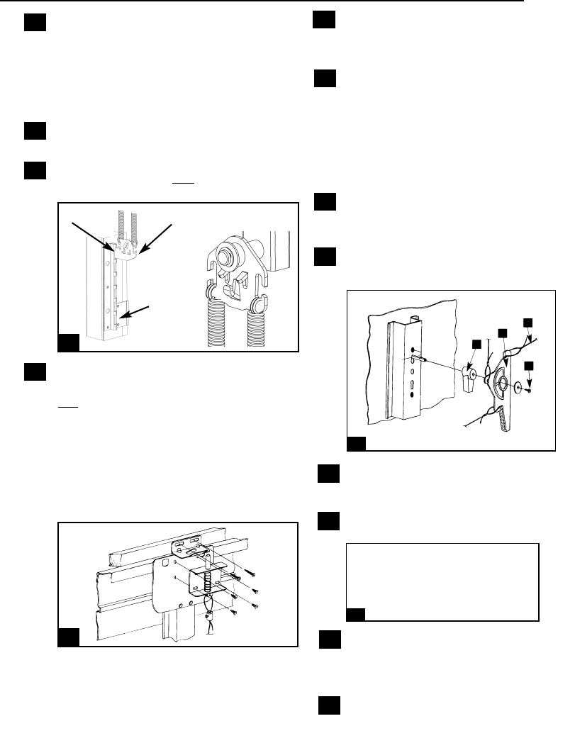
Align holes in latch plates with holes in lo
wer side
seals. Drill pilot holes and secure each plate using two
no.12 x 1
1
/2” self tapping screws. Cut away flexible
lower side seals locally where latch strikes the latch
plate
Fit each wheel bracket to top corner plate of door
using four no.12 x 3/4" self tapping screws ensuring
two vertical slots in wheel bracket are facing down-
wards as shown (Figure E). Slide tracks over wheels
and press firmly up and out in the direction of arrow
until tracks are horizontal. Drill pilot holes in side jambs
and secure each track fixing bracket using two no 12 x
1
1
/2” self tapping screws and two M8 washers, ensur-
ing wheel is in contact with the bottom of the track.
Slide track hangers over ends in orientation
shown in main assembly diagram Slide to a
convenient roof joist
within 200 mm (8”) from end of
track and fix each hanger to joist using ONE no.12 x
1
1
/2” self tapping screw only at this stage. For best
results ensure tracks are hanging horizontally, square
to the frame and parallel to each other At this stage the
tracks should be able to swing sideways.
Slide track end bungs into position in orientation
shown (see Fig. F). Secure each end bung to track
using two off M6 x 30mm hexagon head bolts and two
M6 nyloc nuts ensuring nuts locate firmly into
hexagonal recess in end bung
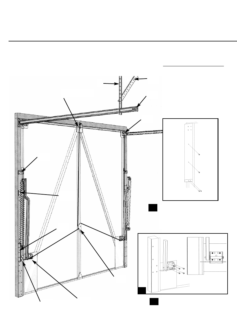
1 FITTING YOUR DOOR
CAUTION ! Please ensure all tools and parts are inside the garage before the door is
placed in the opening.
Assembly diagram (maximizer door gear illustrated)
Numbers refer to installation notes
Swing the pivot arms up, align two holes in
each lo
wer side seal with those in main pivot
br
ackets. Ensure lip on lower side seal locates
against side of jamb f
or full length of side seal.
NO
TE: for special sized doors the bottom of
side seal must be cut short to suit installation.
Drill pilot holes and secure each main pivot
bracket using two M8 x 50mm coach screws
and two M8 washers per side. (See Fig B)
Smooth lower side seals into position. Align
pivot blocks with holes in lower side seals as
shown. (Fig. C) drill pilot holes and secure
using two no.12 x 1
1
/2”: self tapping screws
per block.
1
2
3
4
5
6 11
16
12
Fully open door and prop securely in position.
With the door still open the tr
acks should be parallel
This can be chec
ked by ensuring both roller wheels are
in contact with the tr
ack end bungs. Bolt track braces to
hangers using one M6 x 20mm he
xagon head screw
and one M6 nyloc nut per side Fix each track brace to
joist using one no.12 x 1
1
/2” self tapping screw.
Lock each track hanger in position by fixing to joist
using a second no.12 x 1
1
/2” self tapping screw.
Smooth lower side seals into position, align holes in
lo
wer spring anchor brackets with holes in lower side
seals (Fig.
D). Secure each bracket using three 6mm x
50mm gold self tapping scre
w. There is no need to pilot
dr
ill for these screws.
A
C
F
With the door closed, remo
ve the park pin to
release the latch pin (Figure H) Align the catch
bracket centrally over the latch pin with the
lower face 3mm (1/8”) above the top
door bracket.
Insert 2 off No 12 x 1 1/2” self tapping screws
through screws slots into head timber, use
adjustment on screw slots to ensure correct
alignment
Open the door half way and fit lock following the
instructions in the lock pack supplied with your
door.
LHS
IMPORTANT NOTE
Prior to Fitting the Door
F
or ease of transportation and storage
some doors are supplied without the
upper weather strips attached to the
door panel. These are supplied
separately within the door fixing pack.
If y
our door is of this type then fit the
weather strips as shown below using
4 off No. 12 x
3
/4” self tapping screws
per side
Stand door, safely propped, centrally
between side jambs on two wedges. A
gap of approximately 12mm (1/2”)
should be left between the top of the
door and the lintel
Fit pivot arms to plates in bottom
cor
ners of door using f
our no. 12 x
3
/4”
self tapping screws per side Using
outer holes shown. (See Figure A)
B
Maximizer Gear
D
Latch
Plate
7
8
9
10
E
LHS
Establish gear setting positions for door from label
attached to back of door.
Note setting 1 is top anchor
position
Still with the door in the open position and wearing eye
protection fit lower spring anchors as shown and fit
springs to spring anchors in orientation shown (See fig G).
Note Spring loops to be located on anchor bracket
hooks facing outwards so that spring body is located
in board of spring anchor brackets. When using
centre hook spring will require twisting 180 degrees.
Always use the same number of springs on each side. For
2 springs use outer hooks, for 1 spring use centre hook,
for 3 springs use all hooks. A minimum of 2 through to
maximum of 3 springs per side may be supplied
depending upon door weight.
Check door operation and re-tension if necessary. (See
maintenance label on side seals for details).
NO
TE – Some doors are supplied without the pro
vision
for a top latch to be fitted. In these instances the com-
ponents outlined in instr
uctions 15 & 16 will be surplus
to requirements. If your door is of this type proceed to
instruction 17.
13
14
15
17
H
G
18
19
20
21
22
From front of door ensure that lock handle is
turned fully anti-clockwise From inside slide
lock cam onto spindle in orientation shown
Fit lock lever onto lock cam as shown and
secure to lock spindle using self tapping
screw and washer. (See Figure I)
Locate looped ends of all latch cables securely
in lever slots and adjust for correct operation
ENGAGEMENT NOTE On adjustment of top
latch, please ensure a nominal 6mm (1/4”) pin
engagement through catch br
ac
k
et (Figure J).
Adjustment of other latches should also be set
to 6 mm latch overlap.
Chec
k oper
ation from inside garage to avoid
being locked out
I
J
Typical Lock Assembly Shown.
18
19
19
20
9
15, 16, 21
11
10
8
5
6
19
2
7
3 & 4
Single Gear
Position 1
Position 6
Fit the top latch assemb
ly into the pre-drilled
holes on the top centre door bracket using 4 off
No
. 10 x 1/2” self-tapping screws supplied
(Figure H).
Note: lower spring anchor is not handed.
(i.e. same bracket used on left and right)

Align holes in latch plates with holes in lo
wer side
seals. Drill pilot holes and secure each plate using two
no.12 x 1
1
/2” self tapping screws. Cut away flexible
lower side seals locally where latch strikes the latch
plate
Fit each wheel bracket to top corner plate of door
using four no.12 x 3/4" self tapping screws ensuring
two vertical slots in wheel bracket are facing down-
wards as shown (Figure E). Slide tracks over wheels
and press firmly up and out in the direction of arrow
until tracks are horizontal. Drill pilot holes in side jambs
and secure each track fixing bracket using two no 12 x
1
1
/2” self tapping screws and two M8 washers, ensur-
ing wheel is in contact with the bottom of the track.
Slide track hangers over ends in orientation
shown in main assembly diagram Slide to a
convenient roof joist
within 200 mm (8”) from end of
track and fix each hanger to joist using ONE no.12 x
1
1
/2” self tapping screw only at this stage. For best
results ensure tracks are hanging horizontally, square
to the frame and parallel to each other At this stage the
tracks should be able to swing sideways.
Slide track end bungs into position in orientation
shown (see Fig. F). Secure each end bung to track
using two off M6 x 30mm hexagon head bolts and two
M6 nyloc nuts ensuring nuts locate firmly into
hexagonal recess in end bung
1 FITTING YOUR DOOR
CAUTION ! Please ensure all tools and parts are inside the garage before the door is
placed in the opening.
Assembly diagram (maximizer door gear illustrated)
Numbers refer to installation notes
Swing the pivot arms up, align two holes in
each lo
wer side seal with those in main pivot
br
ackets. Ensure lip on lower side seal locates
against side of jamb f
or full length of side seal.
NO
TE: for special sized doors the bottom of
side seal must be cut short to suit installation.
Drill pilot holes and secure each main pivot
bracket using two M8 x 50mm coach screws
and two M8 washers per side. (See Fig B)
Smooth lower side seals into position. Align
pivot blocks with holes in lower side seals as
shown. (Fig. C) drill pilot holes and secure
using two no.12 x 1
1
/2”: self tapping screws
per block.
1
2
3
4
5
6 11
16
12
Fully open door and prop securely in position.
With the door still open the tr
acks should be parallel
This can be chec
ked by ensuring both roller wheels are
in contact with the tr
ack end bungs. Bolt track braces to
hangers using one M6 x 20mm he
xagon head screw
and one M6 nyloc nut per side Fix each track brace to
joist using one no.12 x 1
1
/2” self tapping screw.
Lock each track hanger in position by fixing to joist
using a second no.12 x 1
1
/2” self tapping screw.
Smooth lower side seals into position, align holes in
lo
wer spring anchor brackets with holes in lower side
seals (Fig.
D). Secure each bracket using three 6mm x
50mm gold self tapping scre
w. There is no need to pilot
dr
ill for these screws.
A
C
F
With the door closed, remo
ve the park pin to
release the latch pin (Figure H) Align the catch
bracket centrally over the latch pin with the
lower face 3mm (1/8”) above the top
door bracket.
Insert 2 off No 12 x 1 1/2” self tapping screws
through screws slots into head timber, use
adjustment on screw slots to ensure correct
alignment
Open the door half way and fit lock following the
instructions in the lock pack supplied with your
door.
LHS
IMPORTANT NOTE
Prior to Fitting the Door
F
or ease of transportation and storage
some doors are supplied without the
upper weather strips attached to the
door panel. These are supplied
separately within the door fixing pack.
If y
our door is of this type then fit the
weather strips as shown below using
4 off No. 12 x
3
/4” self tapping screws
per side
Stand door, safely propped, centrally
between side jambs on two wedges. A
gap of approximately 12mm (1/2”)
should be left between the top of the
door and the lintel
Fit pivot arms to plates in bottom
cor
ners of door using f
our no. 12 x
3
/4”
self tapping screws per side Using
outer holes shown. (See Figure A)
B
Maximizer Gear
D
Latch
Plate
7
8
9
10
E
LHS
Establish gear setting positions for door from label
attached to back of door.
Note setting 1 is top anchor
position
Still with the door in the open position and wearing eye
protection fit lower spring anchors as shown and fit
springs to spring anchors in orientation shown (See fig G).
Note Spring loops to be located on anchor bracket
hooks facing outwards so that spring body is located
in board of spring anchor brackets. When using
centre hook spring will require twisting 180 degrees.
Always use the same number of springs on each side. For
2 springs use outer hooks, for 1 spring use centre hook,
for 3 springs use all hooks. A minimum of 2 through to
maximum of 3 springs per side may be supplied
depending upon door weight.
Check door operation and re-tension if necessary. (See
maintenance label on side seals for details).
NO
TE – Some doors are supplied without the pro
vision
for a top latch to be fitted. In these instances the com-
ponents outlined in instr
uctions 15 & 16 will be surplus
to requirements. If your door is of this type proceed to
instruction 17.
13
14
15
17
H
G
18
19
20
21
22
From front of door ensure that lock handle is
turned fully anti-clockwise From inside slide
lock cam onto spindle in orientation shown
Fit lock lever onto lock cam as shown and
secure to lock spindle using self tapping
screw and washer. (See Figure I)
Locate looped ends of all latch cables securely
in lever slots and adjust for correct operation
ENGAGEMENT NOTE On adjustment of top
latch, please ensure a nominal 6mm (1/4”) pin
engagement through catch br
ac
k
et (Figure J).
Adjustment of other latches should also be set
to 6 mm latch overlap.
Chec
k oper
ation from inside garage to avoid
being locked out
I
J
Typical Lock Assembly Shown.
18
19
19
20
9
15, 16, 21
11
10
8
5
6
19
2
7
3 & 4
Single Gear
Position 1
Position 6
Fit the top latch assemb
ly into the pre-drilled
holes on the top centre door bracket using 4 off
No
. 10 x 1/2” self-tapping screws supplied
(Figure H).
Note: lower spring anchor is not handed.
(i.e. same bracket used on left and right)

CAUTION
This gar
age door has been designed to be as as easy as possible to use, service and automate when installed
correctly. Please therefore take time to read these instructions fully before beginning any work. Note: This door has
been designed to hang on a 70mm x 70mm timber goalpost fr
ame (not supplied).
IMPORTANT INFORMATION
1 This garage door is intended for domestic use only.
2 Garage doors are heavy and may have sharp edges.
Wear protective gloves. Installation should not be undertaken
alone.Care must be taken when handling.
3 Ensure the door is continuously supported before it is secured
and avoid installing in windy conditions.
4 Do not attempt to install or adjust this door if you are unsure of
any of the instructions below.
BEFORE COMMENCING WORK
Remove all wrapping
Before starting: remove all wrapping and check door has been supplied with correct
lifting gear kit. Kit code is on identification label on reverse of door.
Check opening size
Before fitting door, check opening size and squareness of timber frame. The door is made
smaller to give correct clearance within the frame.
Check headroom
There must be a minimum of 42mm headroom above lower face of top timber or lintel.
This must reach back into the garage for at least 1875mm.
Check the “goalpost” frame
The “goalpost” timber frame should be a minimum of 70mm x 70mm square (2
3
/
4
” x 2
3
/
4
”),
in good condition and securely fixed to the surrounding structure.
Tools
All the initial fitting work is done from inside the garage, so all tools and parts should be to
hand there before door is placed in opening.
1
2
3
4
5
You will need:
• 6mm & 10 mm flat bladed screwdriver • Tape measure
• No 2 & 3 posi-drive screwdriver • hammer
• Drill and 2.5mm drill bit (for pilot holes) • Grease
• 13mm A/F socket/spanner • Engineer’s pliers
• 10mm A/F socket/spanner • 19mm x 19mm timber weatherbead to fit under
• 7mm A/F socket/spanner the head of the door frame
• Protective gloves • 70mm x 70mm timber goal post frame
•
Shar
p knif
e
•
W
edges (pac
king pieces)
Note to installer: Please ensure that this instruction sheet remains with the door for the owner’s future reference.
ISSUE B MAY 2005 DPIN 045112
•
DOOR IS HEAVY TO OPEN:
Cause: Spring tension set too low
Solution: Re-set spring tension as detailed on the door maintenance label.
•
DOOR OPENS TOO QUICKLY:
Causes: Spring tension set too high.
Solution: Re-set spring tension as detailed on the door maintenance label.
•
DOOR DOES NOT DELATCH:
Cause: Latch cables may have been set too long.
Solution: If you are not locked out of the garage at the time, then the cables should be set to allow nominal
6mm latch engagement with the latch plates. If you are locked out of the garage, call your installer/supplier
for assistance.
•
DOOR HANDLE FAILS TO TURN:
Probable Cause: A jammed lock barrel.
Solution: Unfortunately this can only be remedied by a service call, however, this is not usually chargeable
during the warranty period. Please contact your supplier for details.
•
KEY FAILS TO TURN IN LOCK:
Probable Cause: Door handle has not been turned to the fully closed position.
Solution: Return the handle to the fully closed (horizontal) position and try again. If the problem still persists,
contact your supplier.
•
LOST KEYS:
Solution:
Contact your supplier. The lock barrel will need to be replaced, but the method for doing this will
vary. If you can get into your garage, the problem can be easily solved by removing the handle assembly
from the door and replacing the lock barrel with a new one. If you are locked out, contact your supplier.
THESE INSTRUCTIONS MUST BE FOLLOWED CAREFULLY
GARAGE DOORS ARE HEAVY AND AWKWARD TO HANDLE. ENSURE
ASSISTANCE IS AVAILABLE AND THAT SAFETY GLOVES ARE WORN.
1. Fix all latches in the fully retracted position.
2. Open door and safely prop in the open position.
3. Remove springs from their hangers. (wear eye protection).
4. With assistance remove prop and close door slowly until fully closed.
5. Prop door in fully closed position and place packers beneath the door between
base of door and floor.
6. Remove all track supports and remove track fixing screws from the frame and
remove.
7. Remove fixings to main pivot brackets, door should now rest on packers.
8. Remove bottom door mounting brackets.
9. Remove main pivot blocks.
10. The door can now be carefully removed from the opening. Seek assistance
in lifting.
11. If door is to be disposed of please do so in a responsible manner in line with the
latest legislation applicable at the time.
Slideaway
Double & Heavy Double Door Gear
INSTALLATION INSTRUCTIONS
11
Slideaway
Single & Maximizer Door Gear
TROUBLE SHOOTING
POWER OPERATION
UPON COMPLETION
2
Fix lower side seals into position using five 1” clout nails
per side.
Check door operation to ensure door opens and closes
satisfactorily.
Check that lock and latches operate correctly.
Ensure all fixings are securely tightened
Fit 19mm
× 19mm timber weatherbead to the underside of
the top timber lintel (Fig K).
Do not paint the spring or any moving parts.
Lubricate all moving parts/pivot points (refer to
maintenance label for details) lubrication is an essential
ongoing requirement to ensure the continuing smooth
operation of your door.
Ask your professional Garage Door Specialist about
remote controlled electric operators.
Lintel
Door
19mm
× 19mm
Weatherbead
1
2
3
4
5
6
7
8
K
DISMANTLING INSTRUCTIONS
In the event of difficulty please contact your local Garage Door Specialist or call our
Gara
g
e Door Helpline.
See main CE label for details
This door is suitable for power operation. In order to conform with current legislation
only independantly tested and certified operators may be fitted. A list of approved
operators is contained on the Declaration of Incorporation supplied with your door.
