
M0011697C
Communication Manual
TYPE S
For Rotary Motor, Linear Motor
Interface

Details of revision history
The third edition (C)
■ Overall
Encoder naming is unified.
■ p. 2-4
Note of node ID setting is added.
■ p. 2-15
Description is added.
Table of SDO response time is added.
■ p. 2-23
SDO Abort Code is updated to latest ETG specifications.
■ p. 2-37 to 2-40
Description of FoE parameter transferring function is added.
■ p. 3-11
Error codes added by ETG are added to AL Status Code.
■ Chapter 4
Writing of "EEPROM" is changed to "non-volatile memory".
■ p. 4-3
The section describing about unit conversion of linear motor / direct drive motor is added.
■ p. 4-7
Description for read access in 0x1010 is updated to detail.
■ p. 4-18 to 4-22
Abort option code description and limitation are added.
Disable option code limitation related to torque slope is added.
Limitations for each option code are added.
■ p. 4-48 to 4-56
Object list of manufacturer specific area is updated with correction and new function addition.
■ p. 4-64 to 4-68
Invalid condition of each filter set value is corrected.
■ p. 4-68
Change time of FF Vibration Suppression Frequency is added.
■ p. 4-69
Filtering frequency setting range of velocity/torque notch filter is corrected.
■ p. 4-83
Description related to assisting function is added.
■ p. 4-86
Description related to system analysis/POFF detection delay time function is added.

Details of revision history
■ p. 4-103, 4-108
Note is added as below.
✔ Alarm DE (Parameter Change Completion) will issued if the value differ from set value is set.
■ p. 4-95
Description related to Drive recorder function/Initialization timeout waiting time is added.
■ p. 4-97 to 4-98
Description related to torque scale is added.
Deceleration stop special function selection in position control mode/RS3 special function selection
setting is added to Extended function selection setting.
Description related to FoE Uploading File Selection is added.
Description related to Gain Switching Condition is added.
■ p. 4-105 to 4-106
Description related to Velocity loop proportional control switching function is added to special
function selection setting.
Torque Limit Switching Condition/Velocity Loop Proportional Control Switching Condition is added to
General Purpose Input Setting.
■ p. 4-110 to 4-111
9 of R1 series motors are added.
■ p. 4-116
Description of DE alarm is added to Motor Encoder Input Selection.
■ p. 4-140 to 4-141
0x2138 is abolished and 0x2139 is added.
0x213A and 0x213B are added.
■ p. 5-12
Description related to drive recorder function/system analysis function is added.
■ p. 5-35
Description related to a recalculated position by "Change set immediately (bit5)" on linear coordinate
system exceeds a limit of position range is added.
■ p. 5-58
Sequence of homing mode is corrected and limitation is added.
■ p. 5-63
Drawing of homing method 33 is corrected.
■ p. 5-67
Drawing of touch probe single event trigger behavior is corrected and description is added.
■ p. 5-76, 5-77
Description of Drive recorder data upload function is added.
Description of System analysis data upload function is added.

Details of revision history
■ p. 5-84, 5-85
Deceleration stop special function selection in position control mode is added.
■ p. 5-86
Restrictions related to deceleration stop in torque control is added.
Restrictions related to special function selection in position control is added.
■ p. 5-95
Description of special function selection setting is added.
No Text on This Page.

Safety Precautions
i
Please read this User Manual and its appendix carefully prior to installation, operation,
maintenance or inspection and perform all tasks according to the instructions provided here. A
good understanding of this equipment, its safety information as well as all Warnings / Cautions
is also necessary before using.
Matters that require attention are ranked as “Danger” “Warning” and “Caution” in this document.
■ Warning Symbol
Denotes immediate hazards that will probably cause severe bodily
injury or death as a result of incorrect operation.
Denotes immediate hazards which will probably cause severe
bodily injury or death as a result of incorrect operation.
Denotes hazards which could cause bodily injury and product or
property damage as a result of incorrect operation.
Caution Even those hazards denoted by this symbol could lead to a serious accident.
Make sure to strictly follow these safety precautions.
■ Prohibited,Mandatory Symbols
Indicates actions that must not be allowed to occur / prohibited
actions.
Indicates actions that must be carried out / mandatory actions.
Danger
Warning
Caution

Safety Precautions
ii
■ Attention in use
Warning
Do not use this device in explosive environment.
Injury or fire could otherwise result.
Do not perform any wiring, maintenance or inspection when the device is hot-wired.
After switching the power off, wait at least 15 minutes before performing these tasks.
Electric shock or damage could otherwise result.
The protective ground terminal ( ) should always be grounded to the unit or control
board. The ground terminal of the motor should always be connected to the protective
ground terminal ( ) of the amplifier.
Electric shock could otherwise result.
Do not touch the inside of the amplifier.
Electric shock could otherwise result.
Do not damage the cable, do not apply unreasonable stress to it, do not place heavy
items on it, and do not insert it in between objects.
Electric shock could otherwise result.
Do not touch the rotating part of the motor during operation.
Bodily injury could otherwise result.

Safety Precautions
iii
Caution
Use the amplifier and motor together in the specified combination.
Fire or damage to the device could otherwise result.
Only technically qualified personnel should transport, install, wire, operate, or perform
maintenance and inspection on this device.
Electric shock, injury or fire could otherwise result.
Do not expose the device to water, corrosive or flammable gases, or any flammable
material.
Fire or damage to the device could otherwise result.
Be careful of the high temperatures generated by the amplifier/motor and the
peripherals.
Burn could otherwise result.
Do not touch the radiation fin of the amplifier, the regenerative resistor, or the motor
while the device is powered up, or immediately after switching the power off, as these
parts generate excessive heat.
Burn could otherwise result.
In terms of designing safety systems using the Safe Torque Off function, personnel
who have expertise of relevant safety standard are supposed to do that job with good
understanding of this instruction manual.
Injury or damage to the device could otherwise result.
Please read the User Manual carefully before installation, operation, maintenance or
inspection, and perform these tasks according to the instructions.
Electric shock, injury or fire could otherwise result.
Do not use the amplifier or the motor outside their specifications.
Electric shock, injury or damage to the device could otherwise result.
Regenerative resistor has instantaneous capacity. Contact our offices if the
instantaneous regenerative power could be high as the result of high-inertia moment
or high-velocity rotation.
■ Storage
Prohibited
Do not store the device where it could be exposed to rain, water, toxic gases or other
liquids.
Damage to the device could otherwise result.

Safety Precautions
iv
Mandatory
Store the device where it is not exposed to direct sunlight, and within the specified
temperature and humidity ranges {- 20°C to + 65°C,below 90% RH
(non-condensing)}.
Damage to the device could otherwise result.
Please contact our office if the amplifier is to be stored for a period of 3 years or longer.
The capacity of the electrolytic capacitors decreases during long-term storage, and
could cause damage to the device.
Damage to the device could otherwise result.
Please contact our office if the amplifier is to be stored for a period of 3 years or longer.
Confirmations such as bearings and the brakes are necessary.
■ Transportation
Caution
When handling or moving this equipment, do not hold the device by the cables, the
motor shaft or detector portion.
Damage to the device or bodily injury could otherwise result.
Keep in mind that it is dangerous at the time of conveyance if it falls and overturns.
Bodily injury could otherwise result.
Mandatory
Follow the directions written on the outside box. Excess stacking could result in
collapse.
Bodily injury could otherwise result.
Use eyebolt of the motor only for transporting itself. Do not use for transportation of
machinery combined with the motor.
Damage to the device or bodily injury could otherwise result.

Safety Precautions
v
■ Installation
Caution
Do not stand on the device or place heavy objects on top of it.
Bodily injury could otherwise result.
Make sure the mounting orientation is correct.
Fire or damage to the device could otherwise result.
Do not drop this device or subject it to excessive shock of any kind.
Damage to the device could otherwise result.
Do not obstruct the air intake and exhaust vents, and keep them free of debris and
foreign matter.
Fire could otherwise result.
Consult the User Manual regarding the required distance inside the amplifier
disposition.
Fire or damage to the device could otherwise result.
Open the box only after checking its top and bottom location.
Bodily injury could otherwise result.
Verify that the products correspond to the order sheet/packing list.
Injury or damage could result.
Take care of falling or overturning of the device during installation.
Use eyebolts of the motor if supplied.
Bodily injury could otherwise result.
Install the device on a metal or other non-flammable support.
Fire could otherwise result.
Make the collision safety device strong enough to resist the maximum output of the
system.
Bodily injury could otherwise result.

Safety Precautions
vi
■ Wiring
Caution
Wiring connections must be secure.
Bodily injury could otherwise result.
Wiring should be completed based on the Wiring Diagram or the User Manual.
Electric shock or fire could otherwise result.
Wiring should follow electric equipment technical standards and indoor wiring
regulations.
An electrical short or fire could otherwise result.
Do not connect a commercial power supply to the U, V or W terminals of the servo
motor.
Fire or damage to the device could otherwise result.
Install a safety device such as a breaker to prevent external wiring short-circuits.
Fire could otherwise result.
Do not bind or band the power cable, input/output signal cable and/or encoder cable
together or pass through the same duct or conduit.
This action will cause faulty operation.
Must add the surge absorbing diode if inductive load as relay connect to the control
signal output of the amplifier. Please take care of polarity of the diode that will be
cause of failure.
Do not connect DC90V or AC power to the DC24V Brake of the servo motor. Also, do
not connect AC400V to the AC200V Fan of the servo motor.
An electrical short or fire could otherwise result.
Please design a sequence that included braking delay time because the
surge-absorbing component for the relay of holding brake of the servo motor gives
braking delay time.
Injury or load falling could otherwise result.
Mandatory
Install an external emergency stop circuit that can stop the device and cut off the power
instantaneously. Install an external protective circuit to the amplifier to cut off the power
from the main circuit in the case of an alarm.
Motor runaway, bodily injury, burnout, fire and secondary damages could otherwise
result.

Safety Precautions
vii
■ Operation
Caution
Do not perform extensive adjustments to the device as they may result in unstable
operation.
Bodily injury could otherwise result.
Trial runs should be performed with the motor in a fixed position, separated from the
mechanism. After verifying successful operation, install the motor on the mechanism.
Bodily injury could otherwise result.
The holding brake is not to be used as a safety stop for the mechanism. Install a safety
stop device on the mechanism.
Bodily injury could otherwise result.
In the case of an alarm, first remove the cause of the alarm, and then verify safety. Next,
reset the alarm and restart the device.
Bodily injury could otherwise result.
Check that input power supply voltage is keeping a specification range.
Damage to the device could otherwise result.
Avoid getting close to the device, as a momentary power outage could cause it to
suddenly restart (although it is designed to be safe even in the case of a sudden restart).
Bodily injury could otherwise result.
Do not use motor or amplifier which is defective or failed and damaged by fire.
Injury or fire could otherwise result.
In the case of any irregular operation, stop the device immediately.
Electric shock, injury or fire could otherwise result.
When using the servo motor in vertical axis, provide safety devices to prevent falls
during the work that will cause an alarm condition.
Injury or damage could result.

Safety Precautions
viii
Prohibited
The built-in brake is intended to secure the motor; do not use it for regular control.
Damage to the brake could otherwise result.
Damage to the device could otherwise result.
Keep the motor’s encoder cables away from static electricity and high voltage.
Damage to the device could otherwise result.
Standard specification servo amplifiers have a dynamic brake resistor. Do not rotate the
motor continuously from the outside when the amplifier is not powered on, because the
dynamic brake resistor will heat up, and can be dangerous.
Fire or burn could otherwise result.
Absolutely do not apply voltage more than the spec to the amplifier because overvoltage
will be cause of part failure.
Damage to the device or bodily injury could otherwise result.
Avoid frequent on and off power supply.
Inner parts might get premature failure in case of repeating ON/OFF of power supply 30
times or more per day, otherwise 5 times or more per hour.
Mandatory
Install an external emergency stop circuit that can stop the device and cut off the power
instantaneously. Install an external protective circuit to the amplifier to cut off the power
from the main circuit in the case of an alarm.
Motor runaway, bodily injury, burnout, fire and secondary damages could otherwise
result.
There is no safeguard on the motor. Use an over-voltage safeguard, short-circuit
breaker, overheating safeguard, and emergency stop to ensure safe operation.
Injury or fire could otherwise result.
Operate within the specified temperature and humidity range.
Servo Amplifier
Temperature 0°C to 55°C
Humidity below 90% RH (non-condensing).
Servo Motor
Temperature 0°C to 40°C
Humidity below 90% RH (non-condensing).}
Burnout or damage to the device could otherwise result.

Safety Precautions
ix
■ Maintenance・Inspection
Caution
Some parts of the servo amplifier (electrolytic capacitor, cooling fan, lithium battery
for encoder, fuse and relay kinds) can deteriorate with long-term use. Please
contact our offices for replacements.
Damage to the device could otherwise result.
Do not touch or get close to the terminal while the device is powered up.
Electric shock could otherwise result.
Be careful during maintenance and inspection, as the body of the amplifier
becomes hot.
Burn could otherwise result.
Please contact your distributor or sales office if repairs are necessary.
Disassembly could render the device inoperative.
Damage to the device could otherwise result.
Prohibited
Do not overhaul the device.
Fire or electric shock could otherwise result.
Do not measure the insulation resistance and the pressure resistance.
Damage to the device could otherwise result.
Absolutely do not unplug the connector while the device is powered up because
hot plug will give damaged by surge to component.
Electric shock or damage could otherwise result.
Do not remove the nameplate cover attached to the device.
■ Disposal
Mandatory
If the amplifier or the motor is no longer in use, it should be discarded as industrial
waste.

Table of contents
x
1. Preface
1.1 Introduction ················································································································ 1-1
1.1.1 Product overview ································································································ 1-1
1.2 Instruction manual ······································································································· 1-2
1.2.1 Contents ··········································································································· 1-2
1.2.2 Precautions related to these instructions ·································································· 1-2
2. Interface
2.1 About EtherCAT ·········································································································· 2-1
2.1.1 Overview ··········································································································· 2-1
2.1.2 EtherCAT profile ································································································· 2-1
2.2 Model (Reference Model) ······························································································ 2-2
2.2.1 OSI Reference Model ·························································································· 2-2
2.2.2 Drive Architecture ······························································································· 2-3
2.3 Settings ····················································································································· 2-4
2.3.1 Node ID ············································································································ 2-4
2.3.2 Physical Communication Specifications ··································································· 2-4
2.4 Communication Specifications ························································································ 2-5
2.4.1 Device Model ····································································································· 2-5
2.4.2 Communication ·································································································· 2-6
2.4.3 EtherCAT Protocol ······························································································ 2-7
2.4.4 Datagram Header ······························································································· 2-7
2.4.5 Command Type ·································································································· 2-8
2.4.6 WKC (Working Counter) ······················································································· 2-9
2.4.7 Frame Processing ······························································································· 2-9
2.5 Addressing Image ······································································································ 2-10
2.5.1 Position Addressing (Auto-Increment Addressing) ···················································· 2-10
2.5.2 Node Addressing (Fixed Addressing) ····································································· 2-10
2.5.3 Logical Addressing ···························································································· 2-11
2.5.4 FMMU(Fieldbus Memory Management Unit) ·························································· 2-11
2.5.5 SM (SyncManager) ··························································································· 2-12
2.5.6 Buffer Mode (3 Buffer Mode) ··············································································· 2-12
2.5.7 Mailbox Mode ·································································································· 2-14
2.6 Accessing to Object Dictionary ····················································································· 2-15
2.6.1 Service Data Object (SDO) ················································································· 2-15
2.6.2 Mailbox Protocol ······························································································· 2-16
2.6.3 CANopen Header Protocol ·················································································· 2-17
2.6.4 SDO Message ·································································································· 2-18
2.6.5 Process Data Object (PDO) ·············································································· 2-29
2.7 Distributed Clocks (DC) ······························································································ 2-31
2.7.1 Clock Synchronization ······················································································· 2-31
2.7.2 System Time ···································································································· 2-31

Table of contents
xi
1
Preface
2
Interface
3
EtherCAT Data Link La
y
er
4
Ob
j
ect Dictionar
y
5
O
p
erations
2.7.3 Clock Synchronization Process ············································································ 2-32
2.7.4 Clock Synchronization Initialization Procedure (example) ·········································· 2-33
2.7.5 SYNC0 / 1 Signal Output Initialization Procedure (example) ······································· 2-33
2.8 Communication Timing ······························································································· 2-34
2.9 EtherCAT State Machine (ESM) ···················································································· 2-35
2.9.1 ESM ·············································································································· 2-35
2.9.2 State ·············································································································· 2-36
2.10 Bootstrap state ········································································································ 2-37
2.10.1 Mailbox protocol of FoE (File access over EtherCAT) ·············································· 2-37
2.10.2 FoE Header protocol ························································································ 2-38
2.10.3 FoE command ································································································ 2-38
3. EtherCAT Data Link Layer
3.1 Device Addressing ······································································································· 3-1
3.1.1 Address Space Overview ······················································································ 3-1
3.1.2 Shadow Buffer for Register Write Operations ···························································· 3-1
3.1.3 EtherCAT Slave Controller Function Blocks ······························································ 3-1
3.2 Address Space ············································································································ 3-2
3.2.1 ESC Information ································································································· 3-4
3.2.2 Station Address ·································································································· 3-6
3.2.3 Write Protection ·································································································· 3-6
3.2.4 ESC Data Link Layer ··························································································· 3-7
3.2.5 Application layer ································································································· 3-9
3.2.6 Process Data Interface (PDI) ··············································································· 3-12
3.2.7 Interrupts ········································································································ 3-13
3.2.8 Error Counter ··································································································· 3-16
3.2.9 Watchdog ········································································································ 3-17
3.2.10 ESI EEPROM Interface (Slave Information Interface) ·············································· 3-18
3.2.11 MII Management Interface ················································································· 3-19
3.2.12 FMMU [7:0] (Fieldbus Memory Management Units) ················································ 3-21
3.2.13 SyncManager (sm [7:0])···················································································· 3-23
3.2.14 Distributed Clocks (DC) ···················································································· 3-26
3.2.15 DC-Time Loop Control Unit ··············································································· 3-30
3.2.16 ESC specific registers ······················································································ 3-37
3.2.17 User RAM ······································································································ 3-38
3.2.18 Process Data RAM ·························································································· 3-38
3.3 EEPROM Mapping ···································································································· 3-39
3.3.1 Address Space Overview ···················································································· 3-39
3.3.2 Address Space Definition ···················································································· 3-39
3.3.3 Slave information Interface Categories ·································································· 3-44

Table of contents
xii
4. Object Dictionary
4.1 Outline of Object Dictionary ··························································································· 4-1
4.1.1 Structure of Object Dictionary ················································································ 4-1
4.1.2 Object code definition ·························································································· 4-1
4.1.3 Access types ······································································································ 4-1
4.1.4 Data Type Area ·································································································· 4-2
4.1.5 Unit in linear/DD motors ······················································································· 4-3
4.2 CoE Communication Area ····························································································· 4-4
4.2.1 Parameter Details of Object Group from 0x1000 ························································ 4-6
4.3 Profile Area ·············································································································· 4-16
4.3.1 Parameter detail of object group following 0x6000 ···················································· 4-18
4.4 Manufacturer Specific Area ·························································································· 4-47
4.4.1 Object Group (0x2000-) ······················································································ 4-47
4.4.2 Parameter detail of object group following 0x2000 ···················································· 4-55
5. Operation
5.1 Test operation ············································································································· 5-1
5.1.1 Installation and Wiring ·························································································· 5-1
5.1.2 Safe Torque Off function ······················································································· 5-1
5.1.3 Movement Confirmation ······················································································· 5-2
5.1.4 Machine Movement Check ···················································································· 5-4
5.2 ESC Power ON Sequence ···························································································· 5-5
5.3 EtherCAT Communication Sequence ··············································································· 5-6
5.3.1 INIT State ·········································································································· 5-6
5.3.2 Pre-Operational State ·························································································· 5-8
5.3.3 Safe-Operational State ························································································· 5-9
5.3.4 Operational State ································································································ 5-9
5.3.5 Boot State ······································································································· 5-10
5.4 Servo amplifier status display ······················································································· 5-13
5.4.1 Normal display ································································································· 5-13
5.4.2 Alarm display ··································································································· 5-13
5.5 Operation Sequence ·································································································· 5-14
5.5.1 Operation Sequence from Power ON to Power OFF ················································· 5-14
5.5.2 Alarm Occurrence Stop Sequence ········································································ 5-18
5.5.3 Alarm Reset Sequence ······················································································ 5-21
5.6 Communication timing ································································································ 5-22
5.6.1 Free Run Mode (Free Run: Asynchronous Operation) ··············································· 5-23
5.6.2 DC Mode (SYNC0 Event Synchronization) ····························································· 5-24
5.6.3 DC Mode (SYNC1 Event Synchronization) ····························································· 5-25
5.7 PDS FSA ················································································································· 5 -26
5.7.1 Abstract ·········································································································· 5-26
5.7.2 FSA(Finite States Automaton) ············································································· 5-27

Table of contents
xiii
1
Preface
2
Interface
3
EtherCAT Data Link La
y
er
4
Ob
j
ect Dictionar
y
5
O
p
erations
5.8 Operation Mode ········································································································ 5-30
5.8.1 Kinds of operation mode ····················································································· 5-30
5.8.2 Function Group "Position" Mode ··········································································· 5-31
5.8.3 Function Group "Velocity" ··················································································· 5-50
5.8.4 Function Group "Torque" ···················································································· 5-53
5.8.5 Function Group "Homing" ··················································································· 5-56
5.8.6 Function Group "Touch Probe" ············································································· 5-67
5.9 SEMI F47 Support Functions ······················································································· 5-70
5.10 Virtual motor operation function ·················································································· 5-71
5.10.1 Setting ·········································································································· 5-71
5.10.2 Restrictions ···································································································· 5-72
5.10.3 Digital operator display ····················································································· 5-73
5.10.4 Operating precautions ······················································································ 5-73
5.11 File transferring function ···························································································· 5-74
5.11.1 Self-programing function ··················································································· 5-74
5.11.2 Parameter download function ············································································· 5-75
5.11.3 Parameter upload function ················································································· 5-76
5.11.4 Drive recorder data upload function ····································································· 5-76
5.11.5 System analysis data upload function ·································································· 5-77
5.12 High speed sampling mode ························································································ 5-78
5.12.1 Setting ·········································································································· 5-78
5.12.2 Dedicated function in high speed sampling mode ··················································· 5-78
5.12.3 Restrictions ···································································································· 5-79
5.13 Scale function ········································································································· 5-80
5.13.1 Scale setting ·································································································· 5-80
5.13.2 Parameters affected by scale setting ··································································· 5-81
5.13.3 Monitors affected by scale setting ······································································· 5-82
5.13.4 Scale conversion coefficient ·············································································· 5-82
5.13.5 Restrictions ···································································································· 5-82
5.14 Extended function selection ······················································································· 5-83
5.14.1 Deceleration stop function with velocity control mode in torque control mode ··············· 5-83
5.14.2 Function abstract ···························································································· 5-83
5.14.3 Deceleration stop special function in position control mode ······································ 5-84
5.14.4 Function abstract ···························································································· 5-84
5.14.5 Restrictions ···································································································· 5-86
5.15 Modulo function ······································································································· 5-87
5.15.1 Modulo setting ································································································ 5-87
5.15.2 Function abstract ···························································································· 5-87
5.16 Protective function ··································································································· 5-90
5.16.1 Position deviation difference excess warning/alarm ················································ 5-90
5.17 Correction table function ··························································································· 5-92
5.17.1 Related parameters ························································································· 5-92
5.17.2 How to set a correction able ·············································································· 5-92

Table of contents
xiv
5.17.3 Correction table operation ················································································· 5-93
5.17.4 Precautions ···································································································· 5-94
5.18 Special function selection setting ················································································· 5-95
5.18.1 How to use of gain switching function ·································································· 5-95
5.18.2 How to use of velocity loop proportional control switching function ····························· 5-95
5.19 Restrictions ············································································································ 5-96
5.19.1 Restriction list ································································································· 5-96

1
Preface
In this chapter, Summary, Positioning, and How to use of this instruction manual are explained.
1.1 Introduction ............................................................................................................. 1-1
1.1.1 Product overview .............................................................................................................................. 1-1
1.2 Instruction manual .................................................................................................. 1-2
1.2.1 Contents ........................................................................................................................................... 1-2
1.2.2 Precautions related to these instructions ......................................................................................... 1-2

1. Preface
1-1
1.1 Introduction
1.1.1 Product overview
Thank you for purchasing the AC servo system, “SANMOTION R” 3E Model. This instruction
manual describes important things to notice to ensure your safety, such as specifications,
installation, wiring, operation, functions and maintenance of the system. Please make sure to
read this instruction manual before use to operate this AC servo system correctly. After reading,
please keep it handy to refer as needed.
■ Summary
This document is a part of instruction manual of R 3E Model EtherCAT servo amplifier issued
by SANYO DENKI.
This instruction manual describes technical specification of how to construct EtherCAT
network communication, physical parameter adjustment, function activation.
For reading, pertinent knowledge about servo amplifier, motion control, network and EtherCAT
etc is required.
■ Related document
Refer another document M0011696, for the information of servo amplifier and especially
"Safety precautions".

1.2 Instruction manual
1-2
1
Preface
1.2 Instruction manual
This manual outlines the specifications, installation, wiring, operations, functions, maintenance, etc. of the AC
servo amplifier "SANMOTION R" 3E Model EtherCAT interface as follows:
1.2.1 Contents
■ Chapter 1 Preface
Product outline, model number, names of components
■ Chapter 2 Interface
Descriptions for EtherCAT interface.
■ Chapter 3 Datalink layer
Explanation of EtherCAT Slave Controller (ESC)
■ Chapter 4 Object dictionary
Descriptions for object dictionary of EtherCAT interface.
■ Chapter 5 Operation
Explanation of operation sequence and how to use test operation
1.2.2 Precautions related to these instructions
In order to fully understand the functions of this product, please read this instruction manual thoroughly
before using the product. After thoroughly reading the manual, keep it handy for reference.
Carefully and completely follow the safety instructions outlined in this manual.
Note that safety is not guaranteed for usage methods other than those specified in this manual or those
methods intended for the original product.
Permission is granted to reproduce or omit a portion of the attached figures (as abstracts) for use.
The contents of this manual may be modified without prior notice as revisions or additions are created
regarding the usage method of the product. Modifications are performed as per the revisions of this manual.
Although the manufacturer has taken all possible measures to ensure the veracity of the contents of this
manual, should you notice any error or omission, please notify the nearest branch office or head office written
in back cover.
Moreover, original text of this instruction manual is Japanese. Original text writing has priority if there is
difference between original text and the other language writing.
No Text on This Page.

2
Interface
In this chapter, EtherCAT interface is explained.
2.1 About EtherCAT ...................................................................................................... 2-1
2.1.1 Overview ........................................................................................................................................... 2-1
2.1.2 EtherCAT profile ............................................................................................................................... 2-1
2.2 Model (Reference Model) ....................................................................................... 2-2
2.2.1 OSI Reference Model ....................................................................................................................... 2-2
2.2.2 Drive Architecture ............................................................................................................................. 2-3
2.3 Settings ................................................................................................................... 2-4
2.3.1 Node ID ............................................................................................................................................ 2-4
2.3.2 Physical Communication Specifications ........................................................................................... 2-4
2.4 Communication Specifications ............................................................................. 2-5
2.4.1 Device Model .................................................................................................................................... 2-5
2.4.2 Communication ................................................................................................................................. 2-6
2.4.3 EtherCAT Protocol ............................................................................................................................ 2-7
2.4.4 Datagram Header ............................................................................................................................. 2-7
2.4.5 Command Type ................................................................................................................................ 2-8
2.4.6 WKC (Working Counter) ................................................................................................................... 2-9
2.4.7 Frame Processing ............................................................................................................................ 2-9
2.5 Addressing Image ................................................................................................. 2-10
2.5.1 Position Addressing (Auto-Increment Addressing) ......................................................................... 2-10
2.5.2 Node Addressing (Fixed Addressing) ............................................................................................. 2-10
2.5.3 Logical Addressing .......................................................................................................................... 2-11
2.5.4 FMMU(Fieldbus Memory Management Unit) ................................................................................. 2-11
2.5.5 SM (SyncManager) ........................................................................................................................ 2-12
2.5.6 Buffer Mode (3 Buffer Mode) .......................................................................................................... 2-12
2.5.7 Mailbox Mode ................................................................................................................................. 2-14
2.6 Accessing to Object Dictionary ........................................................................... 2-15
2.6.1 Service Data Object (SDO) ............................................................................................................ 2-15
2.6.2 Mailbox Protocol ............................................................................................................................. 2-16
2.6.3 CANopen Header Protocol ............................................................................................................. 2-17
2.6.4 SDO Message ................................................................................................................................ 2-18
2.6.5 Process Data Object (PDO) ......................................................................................................... 2-29
2.7 Distributed Clocks (DC) ....................................................................................... 2-31
2.7.1 Clock Synchronization .................................................................................................................... 2-31
2.7.2 System Time ................................................................................................................................... 2-31
2.7.3 Clock Synchronization Process ...................................................................................................... 2-32
2.7.4 Clock Synchronization Initialization Procedure (example) ............................................................. 2-33
2.7.5 SYNC0 / 1 Signal Output Initialization Procedure (example) ......................................................... 2-33
2.8 Communication Timing ........................................................................................ 2-34
2.9 EtherCAT State Machine (ESM) ........................................................................... 2-35
2.9.1 ESM ................................................................................................................................................ 2-35
2.9.2 State ............................................................................................................................................... 2-36
2.10 Bootstrap state .................................................................................................... 2-37
2.10.1 Mailbox protocol of FoE (File access over EtherCAT) ................................................................. 2-37
2.10.2 FoE Header protocol .................................................................................................................... 2-38
2.10.3 FoE command .............................................................................................................................. 2-38

2.1 About EtherCAT
2-1
2
Interface
2.1 About EtherCAT
This chapter describes the technical specifications for the network communication construction
method, physical parameter adjustment method and the function activation method.
An appropriate knowledge of servo amplifiers, motion control, networking and EtherCAT CoE
(CANopen over EtherCAT) is required for the reader of this chapter.
Detailed information of EtherCAT can be obtained from the following ETG (EtherCAT Technology
Group) website:
http://www.ethercat.org/
■ Trademark
EtherCAT® is registered trademark and patented technology, licensed by Beckhoff
Automation GmbH, Germany.
2.1.1 Overview
EtherCAT is an abbreviation of Ethernet for Control Automation Technology. EtherCAT is an open network
communication between master and slave units using the real time Ethernet developed at BECKHOFF
Automation and is controlled by ETG (EtherCAT Technology Group).
Twisted pair or fiber optic cables can be used for the EtherCAT connection and the EtherCAT also makes
various topological configurations possible, such as line, tree, daisy chain, drop line, etc.
Each slave node reads the output data transmitted from the master, while a telegram is forwarded to the
next device. Similarly, the input data is inserted while the telegram passes through. Standard Ethernet
protocol in accordance with IEEE802.3maintained as the communication protocol; therefore, a new
sub-bus construction is unnecessary for the EtherCAT connection.
This protocol allows transport of control data directly to each Ethernet frame. The frame may consist of
multiple sub-telegrams and realized Broadcast and Multicast communications with logical process images
up to a possible 4 gigabytes in size.
A cable length of 100m maximum is possible between devices, and the size of the network is virtually
unlimited since up to 65535 slaves can be connected under the 100BASE-TX Ethernet.
In addition, a switch-based reciprocal connection with ordinary TCP / IP is also possible.
2.1.2 EtherCAT profile
■ IEC61158 Section12
・IEC61158-2-12 (EtherCAT Physical Layer Specification and service definition)
・IEC61158-3-12 (EtherCAT Data-link service definition)
・IEC61158-5-12 (EtherCAT layer service definition)
・IEC61158-6-12 (EtherCAT layer protocol specification)
IEC61158 is the forms of the international fieldbus standards including Ethernet-based field buses with
the descriptions that define the basic communication structure of the networks.
EtherCAT protocol is added as "Type 12" that directs EtherCAT Communication Profiles such as
EtherCAT State Machine (ESM), Process Data Communication System using the features of the
Fieldbus Memory Management Unit (FMMU), CoE Service Channel mapps to the EtherCAT Mailbox,
SyncManager (SM) and synchronization structure using Distributed Clocks (DS).
■ IEC61800 Part7 (Adjustable speed electrical power drive systems)
・IEC61800-7-1 (Generic interface and use of profiles for power drive systems - Interface
definition)
・IEC61800-7-200 (Generic interface and use of profiles for power drive systems - Profile
specifications)
・IEC61800-7-300 (Generic interface and use of profiles for power drive systems - Mapping of profiles
to network technologies)
IEC61800 in Part7, Power Drive System (PDS) profile, defines the functional operations of the servo
drive systems.
Section1defines the generic interface and use of profiles for PDS.
Section200 defines the specifications of profile types. The object dictionary of data protocol, CiA402,
state transition FSA and operation mode functions are explained in Profile type1 (-201) and primarily
SERCOS IDN and phase are explained in Profile type4(-204) in detail.
Section300 defines mapping of network technologies. CANopen and CANopen over EtherCAT are
explained in the Mapping of profile type1 (-301) and the communication protocols such as SERCOS and
Servo drive over EtherCAT are explained in the Mapping of profile type4 (-304).

2. Inteface
2-2
2.2 Model (Reference Model)
2.2.1 OSI Reference Model
Compared with the OSI (Open Systems Interconnection) reference model, the EtherCAT
communication model has no layers in layers 3 - 6.
Comparison of OSI reference model and EtherCAT (CoE) model
Layer OSI reference model EtherCAT model
7
Application
(Application layer)
SDO (Service Data Object : Mailbox)
PDO (Process Data Object)
ESM (EtherCAT State Machine)
ESI (Slave Information Interface)
6 Presentation (Presentation layer)
Empty
5 Session (Session layer)
4 Transport (Transport layer)
3 Network (Network layer)
2
Data link
(Data link layer)
SM (Sync Manager)
FMMU (Field Memory Management Unit
PDI (Process Data Interface)
DC (Distributed Clock)
1
Physical
(Physical layer)
100BASE-TX
E-BUS (LVDS for back plane)
■ Layer 1 (Physical layer)
Takes charge of electrical conversion and mechanical work to send out data to
communication circuits. The pin shapes and cable characteristics are also specified on this
layer.
■ Layer 2 (Data link layer)
Ensures the physical communication path and detects data errors passing through the path.
■ Layer 3 (Network layer)
Selects the communication path to deliver the data and controls the address inside the path.
■ Layer 4 (Transport layer)
Performs data compression, error correction and resends data delivery controls absolutely
and efficiently.
■ Layer 5 (Session layer)
Establishes and releases virtual connection for sending / receiving data between
communication programs.
■ Layer 6 (Presentation layer)
Transforms received data from the session layer into an easier to use form and changes the
data from the application layer into a form applicable for communication.
■ Layer 7 (Application layer)
Provides various services utilizing data communication to users as well as to other programs.

2.2 Model (Reference Model)
2-3
2
Interface
2.2.2 Drive Architecture
Communication architecture
Motor
Application layer and EtherCAT communication profile IEC61158
Drive Profile CiA402
Device Control
State Machine
Functions (Modes of operation)
Homing
Function
Ethernet Node
Torque
Function
Position
Function
Velocity
Function
Touch Probe
Function

2. Inteface
2-4
2.3 Settings
2.3.1 Node ID
Each slave drive in the EtherCAT network can have its own respective node ID and the unique
node ID setting is basically performed in the position addressing mode.
Besides, 0 - 255 axes addresses can be set using the 8bit rotary switch (0x00 to 0xFF: bit 7 to 0)
at the front of the amplifier.
The setting values will be written in the station alias setting register (0x0012) in an address
space after the control power has been turned ON.
When an axis address has changed under the control power ON status, re-input the power to
enable the change in axis address.
Node ID setting method differs due to set value of object 0x20FA-2, as below.
0x20FA-2: Extended station
alias selection
Setting method
0x00
Sets a rotary switch value as lower 8 bit, and extended alias
number (0x20FA-1) value as higher 8 bit.
0x01
Rotary switch value is zero:
Reflects the value defined to address 4 of EEPROM
attached to ESC.
Rotary switch value is except zero:
Reflects the value of rotary switch.
(Write zero to address 4 of EEPROM.)
2.3.2 Physical Communication Specifications
Physical Communication Specifications
Item Specifications Notes
Topology Line
Data flow Line: From the master to the first slave and then on to the last
slave, shuttling back and forth.
Communication
media
Twisted pair cable
Communication
rate
100 Mbit/s
Communication
parameter
settings
Auto-negotiation function with ISO/IEC 8802-3
Auto-crossover function
Cycle time Depends on application
Device address Selected address
Synchronization Special protocol for data change(DC)
Slave telegram Mailbox SDO telegram using EtherCAT CoE specifications
Master telegram Mailbox SDO telegram using EtherCAT CoE specifications
Initialization Input power >> Init >> Pre-Operational >> Safe-Operational >>
Operational mode
Cable length 100m max Between nodes
Node 65,535 max. Single segment

2.4 Communication Specifications
2-5
2
Interface
2.4 Communication Specifications
2.4.1 Device Model
■ Communication
This unit includes the data transfer function via the network architecture base.
■ Object Dictionary
The Object Dictionary affects the application object, the communication object and the state
machine operations used in this device.
■ Application
The communication device function of data conversion, according to the operational
environment, is included in the application.
The Object Dictionary has a role as an interface between communication and application.
The explanation of the device application of each data item in the Object Dictionary is called a
“Device Profile”.
Physical Layer
Data Link
Layer
(DL)
Physical
Layer(PHY)
EtherCAT
Data Link Layer
Process Data Mailbox
FMMU
FMMU
FMMU
FMMU n
Object Dictionary
SDO, PDO PDO Mapping
Application (DS 402 Device Profile)
DL Control / DL Status
DL info
DL Address
Application
Layer
(AL)
Layer
Management
AL Control /
AL Status
Sync Man
Setting
Slave Information
Servo control
Servo
Motor
Ethernet Bus

2. Inteface
2-6
■ Object Index
All objects are addressed with a 16-bit index using a 4-digit hexadecimal number.
Objects are assigned in the Object Dictionary by individual groups.
The Object Dictionary outline prescribed in CoE is as follows:
Object Index Assignment
Index (Hex) Object
0x1000 - 0x1FFF Communication Profile Area
0x2000 - 0x5FFF Manufacturer Specific Profile Area
0x6000 - 0x9FFF Standardized Device Profile Area
0xA000 - 0xFFFF Reserved
2.4.2 Communication
■ Ethernet Protocol
Since EtherCAT is adopting IEEE 802.3 as its standard Ethernet frame, a standard network
controller can be used.
Therefore, system construction is possible on the master side without designing specific
hardware.
“0x88A4” is reserved for the Ether type of EtherCAT and is distinguished from the other
Ethernet frames.
EtherCAT does not require IP protocol.
The frame defines EtherCAT datagrams and divides them into detailed accounts at the
EtherCAT frame header.
Only theType1 EtherCAT frame is processed by the slave in the EtherCAT header.
Ether Type and Ethernet Data Headers
Destination ECT Header FCS
Ethernet Header(14Byte)
Ethernet Data FCS
6 Byte
Datagrams
2 Byte 44
Note
-1498
Byte
4
Byte
EtherType=0x88A4
Data Type of Datagrams=1
Source EtherType
6 Byte
16 bit
Length Type Datagrams
11 bit
1 bit
2 Byte
Res.
4 bit
Data Length of Datagrams=44~1498
Note) Add 1 - 32Bytes when the Ethernet frame is shorter than 64Bytes
(
Ethernet Header + Ethernet Data + FCS
)
Ethernet Frame Datagrams: max.1514 Byte
Preamble
8 Byte

2.4 Communication Specifications
2-7
2
Interface
2.4.3 EtherCAT Protocol
The commands are standardized as default values with the IEC61158 EtherCAT Communication
Profile to simplify network structuring. Each node in a segment can be addressed individually
and the EtherCAT datagrams can be used by one (1) Ethernet. The frame ends at the EtherCAT
datagrams.
EtherCAT Datagrams
2.4.4 Datagram Header
A 10 Byte datagram header at the beginning of the datagram determines how to handle the
following data:
EtherCAT Datagram Header
Field Data Type Value / Explanation
Cmd BYTE EtherCAT command type
Idx BYTE
Index is handled by the master for copy / datagram identification.
This is a numeric identifier. It cannot be changed in a slave.
Address BYTE [4]
Indicates the access method of the slave with a 32-bit address.
・Auto-increment address (16bit device address+16bit offset address)
・Node address (16bit device address+16bit offset address)
・Logical address (32bit logical address)
Len 11bit Data length following these datagrams
R 3bit Reserved, 0
C 1bit
Circulating frame 0 : Frame is not circulating
1 : Frame was circulated before
M 1bit
Contiguous EtherCAT datagrams
0 : The last EtherCAT datagram (nth EtherCAT Datagrams)
1 : EtherCAT provide further contiguity
(Example:2nd EtherCAT Datagrams will abut the 1st EtherCAT Datagrams
IRQ WORD EtherCAT interrupt request register for all slaves is interlocked with the logic OR
Data BYTE [n] Read / Write data
WKC WORD Working counter
ECT Header FCS
Ethernet Header Ethernet Data FCS
14 Byte 2 Byte
1..n EtherCAT Datagrams
44 - 1498 Byte 4 Byte
1
st
EtherCAT Datagrams n
th
EtherCAT Datagrams
2
nd
・・・ ・・・
Datagram Header Data WKC
10 Byte
0~1486 Byte
2 Byte
<- WKC = Working Counter
0
Cmd
8
Idx
16
Address
48
Len
59
R
62
C
63
M
64
IRQ
79
8 bit 32 bit 11 bit 16 bit 3 bit 1 bit
Position Offset
Address Offset
Logical Address
Position Addressing
Node Addressing
Logical Addressing
More EtherCAT Datagrams
16 bit
Ethernet Header
8 bit 1 bit
16 bit

2. Inteface
2-8
2.4.5 Command Type
Address and access method are determined by the 8-bit command at he head of the EtherCAT
datagram. EtherCAT command types are listed below.
Read / Write operations and Read operation are executed before Write operation.
EtherCAT Command Types
CMD Abbreviation Name Explanation
0
(0x00)
NOP No Operation Disregard commands
1
(0x01)
APRD
Auto Increment
Read
Creates the increment address
Sets Read data in the datagram when the receive address is 0.
2
(0x02)
APWR
Auto Increment
Write
Creates the increment address.
Writes data in the memory domain when the receive address
is 0.
3
(0x03)
APRW
Auto Increment
Read Write
Creates the increment address. Sets Read data in datagrams
and writes the data in the same memory domain.
4
(0x04)
FPRD
Configured Address
Read
Sets Read data in datagrams when address is matched.
5
(0x05)
FPWR
Configured
Address Write
Writes data in datagrams when address is matched.
6
(0x06)
FPRW
Configured Address
Read Write
Sets Read data in the EtherCAT datagrams and writes the
data in the same memory domain when the address is
matched.
7
(0x07)
BRD
Broadcast
Read
All slaves set the logical OR of the memory domain data and
datagrams data.
8
(0x08)
BWR
Broadcast
Write
All slaves write data in the memory domain.
9
(0x09)
BRW
Broadcast
Read Write
All slaves set the logical OR of the memory domain data and
the datagram data then write the data in the memory domain
(BWR is not generally used).
10
(0x0A)
LRD
Logical Memory
Read
Sets read data for the datagrams when the receive address is
matched with read setting FMMU
11
(0x0B)
LWR
Logical Memory
Write
Writes the data in the memory domain when the receive
address is matched with write setting FMMU.
12
(0x0C)
LRW
Logical Memory
Read Write
Sets read data for the datagrams when the receive address is
matched with read setting FMMU. Writes the data in the
memory domain when the receive address is matched with
write setting FMMU.
13
(0x0D)
ARMW
Auto Increment
Read Multiple Write
Creates increment address. Inputs read data to the datagrams
when receive address is 0. Other slaves write data in the
memory domain.
14
(0x0E)
FRMW
Configured Read
Multiple Write
Sets read data to the datagrams when address is matched.
Other slaves write data in the memory domain.
15~255(0x0F - 0xFF)
Reserved
Addressing mode of EtherCAT datagrams 32bit Address is explained in the following table (1-7)
EtherCAT Addressing Mode
Mode Field Data Type Value / Explanation
Auto Increment
Address
Position WORD
Each slave increment is respective to its position, and the slave
at Position = 0 will be addressed.
Offset WORD ESC Local register or Memory address
Configured
Station Address
Address WORD
Slave will be addressed when the set axis address matches the
set station address (under the enabled condition)
Offset WORD ESC Local register or Memory address
Logical
Address
Address DWORD
Slave will be addressed when the logical address (set by FMMU)
FMMU configuration matches the address.

2.4 Communication Specifications
2-9
2
Interface
2.4.6 WKC (Working Counter)
Each EtherCAT datagram will end with a 16 bit working counter (WKC).
The working counter counts the device number normally accessed by EtherCAT datagrams.
Also, the working counter is incremented by the ESC (hardware) in which the slave amplifier is
loaded.
Each datagram should have an estimated working counter value calculated in the master.
The master can confirm if EtherCAT datagrams have executed processing or not by comparing
the estimated value to counted by the WKC and the result of the commands to each slave.
Working Counter Increment
Command Data Type Increment
Read Command
Failed No change
Read succeeded +1
Write Command
Failed No change
Write succeeded +1
Read / Write Command
Failed No change
Read succeeded +1
Write succeeded +2
Read / Write succeeded +3
2.4.7 Frame Processing
R 3EModel EtherCAT amplifier has two (2) parts and the frame processing order (processing) is
according to the logical port number.
Frame Processing Order
Usage Port Frame Processing Order
1 Port
Port0 -> Processing -> Port 0
Port1 -> Processing -> Port 1
2 Ports
Port0 -> Processing -> Port 1 => Port 1 -> -> -> Port 0
Port1 -> -> -> Port 0 => Port 0 -> Processing -> Port 1
The direction via the EtherCAT processing unit is called “Processing” and the direction that does
not pass through the processing unit is called “Forwarding”.
Auto
Forward
Auto
Forward
EtherCAT
Processing Unit
Port 0 Port 1
Port 0 Closed
Loop back
Port1Closed
Loop back function
EtherCAT Servo Amplifier

2. Inteface
2-10
2.5 Addressing Image
2.5.1 Position Addressing (Auto-Increment Addressing)
Position addressing is a command to access slaves from the master according to the connection
order (physical position).
Each slave device provides one (1) 16-bit address field every time datagrams pass through and
a slave “0x0000”will be addressed and will respond when receiving the address field.
Position addressing image is as follows: Frame must be transmitted under the position setting of
“0x0000” when addressing the 1
st
axis and “0xFFF9” when addressing the 8
th
axis.
Position Addressing Image (Example: Addressing the 8
th
axis)
2.5.2 Node Addressing (Fixed Addressing)
The slave matched to the address set at station register (0x0010) from the master by position
addressing is normally addressed in node addressing.
This enables access without fail even when a device is added, the segment topology has
changed and/or the slave has been removed.
The respective slave node address is set with the rotary switch at the front of the amplifier and
CoE Object Dictionary: an added value of the extension station alias (0x20FA) in the station alias.
Therefore, identification is possible even if the connection order differs. Also, this address pattern
is accessible by setting in DL Control.
0xFFFB
0x0FFC
0xFFFD
0xFFFE
Master
Slave I/O
3,4,5,6
Slave amplifier
1
Slave amplifier
2
Slave amplifier
7
Slave amplifier
8
0xFFF9 0xFFFA 0xFFFF 0x0000
0x07D0
0x07D1
0x07D2
0x07D3
Master
Slave I/O
3,4,5,6
Slave amplifier
1
Slave amplifier
2
Slave amplifier
7
Slave amplifier
8
0x03E9 0x03EA 0x03EB 0x03EC

2.5 Addressing Image
2-11
2
Interface
2.5.3 Logical Addressing
A 32-bit address field for logical addressing inside the segment is used as one (1) address value.
Logical addressing is not done individually but addresses the 4GB segment width of the logical
address space.
This section can be used for any slave number and can translate the 32 bit logical address to a
physical address using the internal address mapping method of the Fieldbus Memory
Management Unit (FMMU).
Each FMMU channel maps the logical address space that abuts the contiguous physical address
space of one of the slaves.
Logical addressing image is shown below.
Logical Addressing Image
2.5.4 FMMU(Fieldbus Memory Management Unit)
FMMU (Fieldbus Memory Management Unit) translates the ESC physical address and the 4GB
(32bit channel) master logical address.
Each FMMU channel can manage a logical address controlled in the master and physical
address extending over the respective slave in batch by allocating the contiguous logical
address space of the master to the contiguous physical address space of the slaves.
The types of access configurations supported by FMMU are “Read”,”Write” and ”Read / Write”.
Ethernet HDR
Logic space
4GByte(32bit)
0
FCS
Telegram
Structure
HDR 1 AMP Data HDR n Data n HDR 2 I/O Data
AMP
Data
I/O
Data
Data n
Sub-telegram 1 Sub-telegram2 Sub-telegram n
Master Slave amplifier Slave amplifier Slave I/O Slave I/O

2. Inteface
2-12
2.5.5 SM (SyncManager)
ESC memory can be used for data conversion between the master and the slave microcontroller
without any limitation; however, it has some weak points because the internal ESC is addressed
for using communication memory.
■ The data integrity will not be guaranteed.
Signals must be executed with software for coordinate data conversion.
■ The data security will not be guaranteed.
It is necessary to process the data security mechanism with the software.
■ Both the EtherCAT master and slave (s) must poll the memory until either master or slave has
confirmed the access completion notification.
Definite SM enable and normal data reception are converted between the master and slave and
generate change notification interrupts to both sides.
SM is set in the master and uses a buffer set in the memory area for data conversion.
The communication direction is configured the same as the buffer and mailbox modes.
Access to this buffer is controlled by SM hardware, and it is necessary to access the Start
address first. If not, access will be refused.
The entire buffer will be accessible after the start address is accessed.
The buffer ends with access to the end address and the buffer status will change. An interrupt
will also be generated when the watchdog trigger pulse has been set.
The end address cannot be accessed twice in one frame.
Two (2) communication modes are supported in SM.
■ Buffer Mode
Buffer mode enables access to the communication buffer at any time on both the EtherCAT
master and slave side.
The reception side can always Read the latest buffer written on the transmission side. The
transmission side can always update the buffer value.
However, old data will be dropped when the Write buffer is faster than the Read.
Buffer mode is generally used for PDO communications of T x PDO・R x PDO.
■ Mailbox Mode
Data will not be lost in mailbox mode because of the handshaking mechanism associated with
data conversion.
Either the EtherCAT master or slave can access the buffer, but only when the other side has
ended its access.
To begin, the transmission side Writes on the buffer, and the next Write command is locked
until Read by the reception side.
Mailbox mode is generally used as an application layer protocol. The SM reception buffer will
change in the master only when FCS (Frame Check Sequence) is normal. Therefore, the
buffer will respond immediately after the frame ends.
The SM setting register is assigned from the address 0x0800.
2.5.6 Buffer Mode (3 Buffer Mode)
Buffer mode enables simultaneous data Read/Write on both the master and slave and is called 3
Buffer Mode.
Physically, three (3) same-sized buffers are allocated in this buffer mode and these set the start
address as well as the first buffer size at configuration register SM 0-7 of 0x0800.
This buffer address will be defined for data Read/Write to be used for the master and slave.
Accessing the first (0) address width is performed by SM with automatic switching accessing to
one of the three buffers.
Therefore, the master and slave only need to access the buffer (0) address.
Also, the memory to be used for buffers (1) and (2) will be reserved automatically and disabled.
Please consider this domain carefully when setting another SM.
Generally, one buffer among the three is for Write use, one for Read use and another is reserved
for Write use.

2.5 Addressing Image
2-13
2
Interface
Shows the definition and data conversion example under the setting of: Start address: 0x0100
Data length: 0x0100
Buffer address Object index
0x1000 - 0x10FF
Buffer 0
(Visible)
0x1100 - 0x11FF
Buffer 1
(Invisible disable)
0x1200 - 0x12FF
Buffer 2
(Invisible disable)
0x1300 - Next useable domain
Buffer Allocation for SyncManager Buffer Mode
Conversion example of SyncManager Buffer Mode (Master => Slave)
SM status register reflects the current status and the latest Write buffer status is displayed as in
interrupt status.
The latest Write buffer status shows “3” until the first Write of the SM buffer.
Both the master and slave access Buffer 0
because SM controls all buffers.
Sets only Buffer 0 for SM setting.
Master
Write end
Read latest
available data
Buffer 2
data0
data0 data0 data0
Read end
・・・ Go on Reading
Read latest
available data
EtherCAT Next PDI Microcontroller
Write begin
Write begin
Exchange buffer
(If frame is ok)
Exchange buffer
(If new data available)
Buffer 0
data1 data1 data1
data1 data1 data1
(Full)
Buffer 1 Buffer 2
data0 data0 data0
data0 data0 data0
(Empty)
Buffer 1
(Empty)
Buffer 0
data1 data1 data1
data1 data1 data1
(Full)
Buffer 0
data1 data1 data1
data1 data1 data1
Buffer 2
(Empty)
Buffer 1
data2 data2 data2
data2 data2 data2

2. Inteface
2-14
2.5.7 Mailbox Mode
It is guaranteed that all transmitted data will be delivered to the reception side because the
Write/Read are converted with handshaking in the mailbox mode.
Mailbox mode uses only one (1) size buffer set in advance and will be able to be used as a
mailbox buffer after the initial settings and boot to SM.
When the initial data writing to the data is complete, write access will be blocked and the data
can be read on the reception side.
After the data has been read normally, writing access to the buffer is permitted again.
The time required for data Read/Write is not important in this mode.
Transferring example of Mailbox Mode (Slave to Master)
Mailbox Empty
Master
WKC=0
Slave (Microcontroller)
Read
EtherCAT
Failed
Data Data Data
Data Data Data
Data Data Data
Mailbox Full
Write
Write end Successful
Read
WKC=1
Read
Read
Mailbox Empty
… Data
Successful

2.6 Accessing to Object Dictionary
2-15
2
Interface
2.6 Accessing to Object Dictionary
R3E Model EtherCAT amplifier supports CoE (CANopen over EtherCAT) with two (2) methods
provided for accessing the Object Dictionary device.
■ Service Data Object (SDO)
■ Process Data Object (PDO)
2.6.1 Service Data Object (SDO)
The master can control many of the slave amplifier parameters such as device settings and the
monitor, through Read/Write in the Object Dictionary entry, using SDO transfer.
The master, supporting EtherCAT CoE, performs SDO transfer to each slave device.
The data changes and the Read R_SDO is requested by T_SDO and transmitted from the SDO
master. When writing to entry of the object dictionary (it has "Yes" at NVRAM column of object list
in chapter 4), it saved to non-volatile memory.
Saving to non-volatile memory by SDO requires times around as below according to data size.
Data size Typical time Maximum time
2 bytes (including 1 byte) 25 ms 65 ms
4 bytes 35 ms 70 ms
8 bytes 45 ms 80 ms

2. Inteface
2-16
2.6.2 Mailbox Protocol
The mailbox functions as a communication direction of master to slave / slave to master and
supports various DL user protocols with an independent communication system differing from
logical addressing.
Data transfer from slave to slave must be processed by the master.
The Mailbox Header has an address field in the master that enables re-direction service.
Mailbox uses two (2) SyncManager (SM) channels: one (1) in each direction.
(Example:SM0: Master -> Slave direction,SM1: Slave -> Master direction)
The physical addressing method, with no FMMU, is necessary in mailbox communication
instead of logical addressing because mailbox communication addresses a single slave
intermittently.
Diagram for Mailbox - Interface and protocol configurations are shown below.
Mailbox interface
Mailbox Header CANopen Header Cmd specific data
0
Length
16
Address
32
Channel
38
Prio
40
Type
44
Cntr
ECT Header FCS1
st
ECT Datagrams n
th
ECT Datagrams
2
nd
・・・ ・・・
Datagram Header Data WKC
0 - 1486 Byte
2 Byte
0
Cmd
16
Address
48
Len
59
R
62
C
63
M
64
IRQ
79
8 bit 32 bit 11 bit 3 bit
Ethernet Header
1 bit8 bit
10 Byte
Mailbox Protocol WKC
6 Byte
16 bit 16 bit 2 bit 6 bit 4 bit 4 bit Max. 1478 Byte
Number
2 Byte
9 bit
Res
3 bit
Type Cmd specific data
4 bit
1 bit 16 bit
example: SM0=Mailbox output : 0x1800 Setting time(Master => Slave)
-> CoE request time Offset = 0x1800
SM1=Mailbox input : 0x1C00 Setting time (Slave => Master)
-> CoE response time Offset = 0x1C00
16
Position
32
Offset
16 bit 16 bit
8
Idx

2.6 Accessing to Object Dictionary
2-17
2
Interface
Mailbox Header Configurations
Name
(Abbreviation)
Data
Length
Explanation
Length (Len) 2 Byte Data length to abut the next
Address (Ad) 2 Byte Sender’s station address
Channel (Ch) 6 bit Reserved (0x00)
Priority (Pr) 2 bit Reserved
Priority(0x00 - 0x03)
Type (Typ) 4 bit Mailbox type. Protocol identifier for contiguous data
0 : Mailbox Error
3 : CoE (CAN open over EtherCAT)
Counter (Ct) 4 bit Sequence number
Incremented in every mailbox service as a duplicate detection.
(Only 1 – 7 can be used because of compatibility to an old version)
2.6.3 CANopen Header Protocol
“CANopen Header” is configured with a 2Byte identifier composed of “Number” and “Type”.
“CANopen Header” configuration is shown below.
CoE Command Configuration
Name
(Abbreviation)
Data
Length
Explanation
Number (Num) 9 bit PDO number (PDO Use only in transmission time)
0x000 - 0x1FF
Type (Type) 4 bit Message Type
0 : Reserved
1 : Emergency Message
2 : SDO Request
3 : SDO Response
4 : Reserved (TxPDO)
5 : Reserved (RxPDO)
6 : Reserved (Remote transmission Request of TxPDO)
7 : Reserved (Remote transmission Request of RxPDO)
8 : SDO Information
9 - 15 : Reserved

2. Inteface
2-18
2.6.4 SDO Message
SDO message is configured by “CANopen Header” and “SDO Data frame”.
Data transfer capacity is up to 4Byte standard and is possible for up to 1470Byte using the
“optional Data” domain.
Since most of them are smaller than 4Byte in the R 3E Model EtherCAT CoE amplifier, an
expedited SDO transfer is possible.
SDO message configuration is shown below.
SDO Message List (example)
SDO Message Configuration
Name
(Abbreviation)
Data
Length
Explanation
SDO Control 1 Byte Standard CANopen SDO service
Index 2 Byte Object address by index
Sub-index 1 Byte Object address by sub-index
Data 4 Byte Data for SDO service
Option Data 1 - 1470
Byte
Transmission possible for heavier than 4Byte data with 1 frame at
the time of Option command
(Can be used up to full mailbox size)
■ SDO Command
Data Read / Write by the master begins by transmitting a command code “Index” and
“Sub-index”.
The slave responds to the request by returning the request data.
The same “Index” and “Sub-Index (Sub-idx)” of the request are added to the SDO response.
The response data length is determined by the SDO Command (cmd).
The slave returns an error message when the message is not accepted (Refer to SDO error
messages). The explanation for each command will be shown starting on the next page.
SDO Message List
Command Page/Diagram Notes
SDO Download Expedited Request Diagram1
SDO Download Expedited Response Diagram 2
SDO Upload Expedited Request Diagram 3
SDO Upload Expedited Response Diagram 4
SDO Download Normal Request Diagram 5
SDO Download Normal Response Diagram 2 Same as Diagram 2
SDO Upload Normal Request Diagram 3 Same as Diagram 3
SDO Upload Normal Response Diagram 6
Command specific Abbreviation Definition List
0
Size Indicator :
0
S I
1
Transfer Type :
1
T T
2
Data Set Size :
2
D S
4
Complete Access :
4
C A
5
Command Specific :
5
C S
0
SDO Control :
0
SDO
8
Index :
8
Idx
24
Sub-Index :
24
Sub
32
Complet Size :
32
Cmp S
Mailbox Header CANopen Header
8 Byte
8 Bit 16 Bit
Command specific data
2 Byte Max. 1478 Byte
SDO Control
8 Bit
Index Sub-Index Data Optional Data
32 Bit
1 - 1470 Byte

2.6 Accessing to Object Dictionary
2-19
2
Interface
■ SDO Download Expedited Request
Diagram 1 : SDO Download Expedited Request
■ SDO Download Expedited Response
Diagram 2 : SDO Download Expedited Response
CANopen Header Command specific data Mbx Header
16
Ad
32
Ch
38
Pr
40
Typ
44
Ct
2 Byte 2 Byte 2 bit 6 bit 4 bit 4 bit
0
Num
9 bit
9
R
3 bit
12
Type
4 bit
0
S I
1
T T
5
C S
1 bit
2
D S
2 bit
4
C A
1 bit 3 bit
1 bit
0x03: Download Response
0x00: Reserved
0x00: Zero-fixed
Slave
Master
0
Len
32
Reserved
63
1 Byte2 Byte
8
Idx
24
Sub
4 Byte
0x03: SDO Response
0x03: CoE
0x0A: CANopen H. - Cmd Spec Data
32
Reserved
63
1 Byte 1 Byte 2 Byte 4 Byte
0
SDO
8
Idx
24
Sub
0
SDO
8
Idx
24
Sub
32
Data
0
Len
16
Ad
32
Ch
38
Pr
40
Typ
44
Ct
2 Byte
2 Byte 2 bit 6 bit 4 bit 4 bit 1 Byte
0
Num
9 bit
9
R
3 bit
12
Type
4 bit 1 Byte 2 Byte 4 Byte
0
S I
1
T T
5
C S
1 bit
2
D S
2 bit
4
C A
1 bit 3 bit 1 Byte
32
Data1
56
Data4
6340
Data2
48
Data3
1 Byte 1 Byte 1 Byte
1 bit
2 Byte
1 Byte
CANopen Header Command specific data
Slave
Mbx Header
Master
8
Idx
24
Sub
0x02:SDO Request
0x03:CoE
0x0A:CANopen H. + Cmd Spec Data
0x01: Data Set Size Specification
0x01: Download Request
0x00: 4 Byte Data(Data1 - 4),0x02:2 Byte Data(Data1,2)
0x01: 3 Byte Data(Data1 - 3),0x03:1 Byte Data(Data1)
0x01: Expedited Transfer
0x00: Reserved

2. Inteface
2-20
■ SDO Upload Expedited Request
Diagram 3 : SDO Upload Expedited Request
■ SDO Upload Expedited Response
Diagram 4 : SDO Upload Expedited Response
0
S I
1
T T
5
C S
1 bit
2
D S
2 bit
4
C A
1 bit 3 bit
CANopen Header Command specific data Mbx Header
16
Ad
32
Ch
38
Pr
40
Typ
44
Ct
2 Byte
2 Byte 2 bit 6 bit 4 bit 4 bit 1 Byte
0
Num
9 bit
9
R
3 bit 4 bit 1 Byte 2 Byte 4 Byte
1 bit
0
Len
Slave
Master
0
SDO
8
Idx
24
Sub
32
Data
12
Type
1 Byte
32
Data1
56
Data4
6340
Data2
48
Data3
1 Byte 1 Byte 1 Byte 2 Byte 1 Byte
8
Idx
24
Sub
0x03: SDO Response
0x03: CoE
0x0A: CANopen H. + Cmd Spec Data
0x01: Data Set Size Specification
0x02: Upload Response
0x00:4 Byte Data(Data1 - 4),0x02:2 Byte Data(Data1,2)
0x01:3 Byte Data
(Data1 - 3),0x03:1 Byte Data(Data1)
0x01: Expedited Transfer
0x00: Reserved
CANopen Header Command specific data
Slave
Mbx Header
16
Ad
32
Ch
38
Pr
40
Typ
44
Ct
2 Byte
2 Byte 2 bit 6 bit 4 bit 4 bit
0
Num
9 bit
9
R
3 bit 4 bit
0
S I
1
T T
5
C S
1 bit
2
D S
2 bit
4
C A
1 bit 3 bit
1 bit
0x02: Upload Request
0x00: Zero
Master
0
Len
12
Type
32
Reserved
63
1 Byte2 Byte
8
Idx
24
Sub
4 Byte
0x02: SDO Request
0x03: CoE
0x0A: CANopen H. + Cmd Spec Data
0x00: Reserved
32
Reserved
63
1 Byte 1 Byte 2 Byte 4 Byte
0
SDO
8
Idx
24
Sub

2.6 Accessing to Object Dictionary
2-21
2
Interface
■ SDO Download Normal Request
Diagram 5 : SDO Download Normal Request
■ SDO Download Normal Response
SDO Download Normal Response has the same configuration as SDO Download Expedited
Response
Please refer to Diagram 2: SDO Download Expedited Response
0
SDO
8
Idx
24
Sub
32
Cmp S
0
Len
16
Ad
32
Ch
38
Pr
40
Typ
44
Ct
2 Byte 2 Byte 2 bit 6 bit 4 bit 4 bit 1 Byte
0
Num
9 bit
9
R
3 bit
12
Type
4 bit 1 Byte 2 Byte
0
S I
1
T T
5
C S
1 bit
2
D S
2 bit
4
C A
1 bit 3 bit
8
Index
1 Byte
24
Sub-Index
1 bit 2 Byte
0x01: Data Set Size Specification
0x01: Download Request
0x00: Normal Transfer
0x00: Zero
CANopen Header Command specific data
Slave
Mbx Header
Master
56
Data n - 10
4 Byte
56
Data n - 10
32
Complete Size
4 Byte
0x02: SDO Request
0x03: CoE
n >= 0x0A: CANopen H. + Cmd Spec Data
n-10 Byte
n-10 Byte
n – 10:Data Length
※

2. Inteface
2-22
■ SDO Upload Normal Request
“SDO Download Normal Response” has the same frame configuration as “SDO Upload
Expedited Request”.
Please refer to Diagram 3 : SDO Upload Expedited Request
■ SDO Upload Normal Response
Diagram 6 : SDO Upload Normal Response
0
SDO
8
Idx
24
Sub
32
Cmp S
0
Len
16
Ad
32
Ch
38
Pr
40
Typ
44
Ct
2 Byte
2 Byte 2 bit 6 bit 4 bit 4 bit 1 Byte
0
Num
9 bit
9
R
3 bit
12
Type
4 bit 1 Byte 2 Byte
0
S I
1
T T
5
C S
1 bit
2
D S
2 bit
4
C A
1 bit 3 bit
8
Index
1 Byte
24
Sub-Index
1 bit
2 Byte
0x01: Data Set Size Specification
n-10: Data Length
※
0x00: Normal Transfer
0x00: Zero
CANopen Header Command specific data
Slave
Mbx Header
Master
56
Data n - 10
4 Byte
56
Data n - 10
32
Complet Size
4 Byte
0x03: SDO Response
0x03: CoE
N >= 0x0A: CANopen H. + Cmd Spec Data
n-10 Byte
0x02: Upload Response

2.6 Accessing to Object Dictionary
2-23
2
Interface
■ Abort SDO Transfer
The slave returns an error message as a response to the SDO request when the SDO message
has not been accepted for some reason (value is out of set range, etc.)
The Abort SDO message structure details and abort code list are as follows:
Diagram 7 : Abort SDO Transfer Request
SDO Abort Code
SDO Error Code Explanation
0x05 03 00 00 Toggle bit did not change
0x05 04 00 00 SDO Protocol Timeout
0x05 04 00 01 Client/Server Command Code disability unknown
0x05 04 00 05 Out of memory range
0x06 01 00 00 An access is not corresponding to the object
0x06 01 00 01 Read has been executed to the object corresponding to Write only
0x06 01 00 02 Write has been executed to the object corresponding to Read only
0x06 01 00 03
Sub index cannot write. It requires clearing of sub index 0 for write access.
0x06 01 00 04
SDO complete access doesn't support variable length object like as ENUM object type.
0x06 01 00 05
Object length exceeds mailbox size.
0x06 01 00 06
SDO download blocked because the object is mapped to RxPDO.
0x06 02 00 00 The object does not exist in the Object Dictionary
0x06 04 00 41 Cannot map the object with PDO
0x06 04 00 42 The number of mapping objects or the data length has exceeded PDO limitation
0x06 04 00 43 Non-compatibility of generic parameters
0x06 04 00 47 Non-compatibility of generic internals of device
0x06 06 00 00 Access failure because of hardware error (Failure by write prohibition setting)
0x06 07 00 10 Data type not coordinated because service parameter length does not match
0x06 07 00 12 Data type not coordinated because service parameter length is too long
0x06 07 00 13 Data type not coordinated because service parameter length is too short
0x06 09 00 11 Sub-index does not exist
0x06 09 00 30 Exceeds the parameter value range (Exclusive for Write access)
0x06 09 00 31 Write parameter is too large
0x06 09 00 32 Write parameter is too small
0x06 09 00 36 The maximum value is smaller than the minimum value
0x08 00 00 00 General error
0x08 00 00 20 Cannot transfer or store data into an application
0x08 00 00 21 Cannot transfer or store data into an application because of local control
0x08 00 00 22 Cannot transfer or store data into an application under present device state
0x08 00 00 23 Object Dictionary does not exist
0
S I
1
T T
5
C S
1 bit
2
D S
2 bit
4
C A
1 bit 3 bit
CANopen Header Command specific data Mbx Header
16
Ad
32
Ch
38
Pr
40
Typ
44
Ct
2 Byte
2 Byte 2 bit 6 bit 4 bit 4 bit 1 Byte
0
Num
9 bit
9
R
3 bit 4 bit 1 Byte 2 Byte 4 Byte
1 bit
0x04: Abort Transfer Request
0x00: Zero
0
Len
Slave
Master
0
SDO
8
Idx
24
Sub
32
Data
12
Type
1 Byte
32
Abort Code
63
4 Byte
2 Byte
8
Idx
24
Sub
0x02: SDO Request
0x03: CoE
0x0A: CANopen H. + Cmd Spec Data

2. Inteface
2-24
■ Emergency (EMCY)
Emergency object will be transferred by the master to the request command for mailbox input at
the time of error occurrence inside the device.
This object permits transfer only once to one error event.
In other words, an emergency object will not be transferred unless a new error occurs in the
device.
Diagram 8:EMCY Emergency
Error Code List
Error Code Explanation
0x0000 Error reset or No error
0x1001 SOE Invalid service
0x1002 SOE Unsupported
0x1101 SDO Invalid command
0x1102 SDO Invalid header
0x1103 SDO Unsupported
0xA000
SM Transfer Error: Transition from PRE-OP to SAFE-OP unsuccessful
0xA001
SM Transfer Error: Transition from SAFE-OP to OP unsuccessful
0 Err Code 24 Data 64 0 Len 16Ad 32Ch 38Pr 40Typ 44Ct
2 Byte
2 Byte 2 bit 6 bit 4 bit 4 bit 1 Byte
0 Num
9 bit
9 R
3 bit
12 Type
4 bit 2 Byte
1 Byte
Error Code
Data
Error Register
CANopen Header Command specific data
Slave
Mbx Header
Master
5 Byte
24 Data 64
4 Byte
0x01:Emergency
0x03:CoE
n >= 0x0A:CANopen H. + Cmd Spec Data
16 Err Reg
0 Error Code
2 Byte
16 Error Register
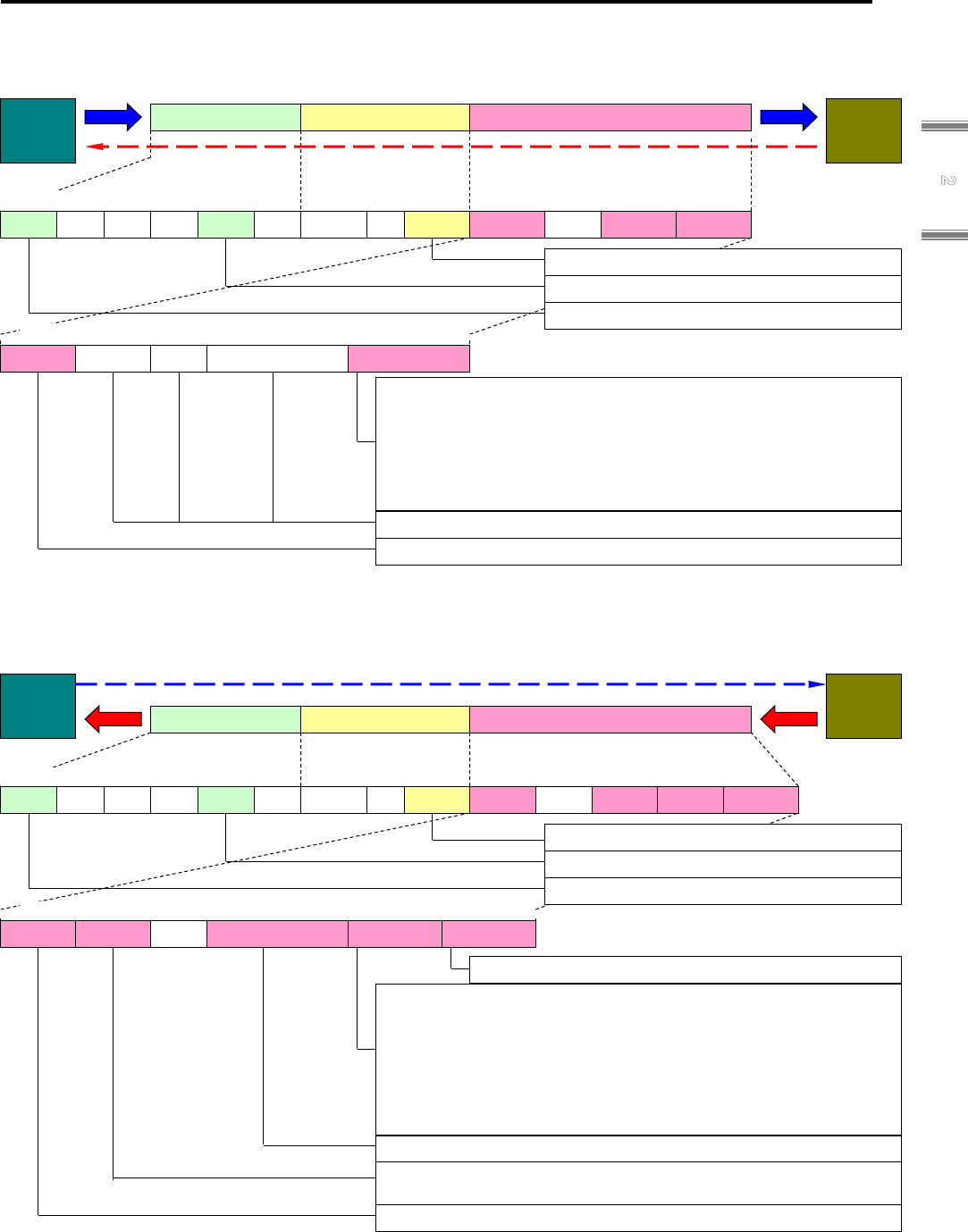
2.6 Accessing to Object Dictionary
2-25
2
Interface
■ SDO Information
Object List Request
Diagram 9 : Get OD List Request (Object Dictionary Request)
Object List Response (Object List Segment Response)
Diagram 10 : Get OD List Response (Object Dictionary Response)
0x00:Object number requested on 5 different lists
0x01:Response transfer of entire object in Object Dictionary
0x02:Response transfer of only R x PDO of the mappable object
0x03:Response transfer of only T x PDO of the mappable object
0x04:Response transfers of the object necessary for backup for
device replacement only
0x05:Response transfer of the object to be used for Startup
parameters only.
0x00:Last SDO Information Flag
0x01:SDO information abuts
Slave
Master
0x02:Contiguous Flag Number
0x02:Get Object Dictionary Response
48
Index
48
Idx
Object List Index
(n-8)byte
(n-8)byte
CANopen Header Command specific data Mbx Header
word word 6bit 2bit 4bit 4bit 9bit 3bit 4bit byte byte word word
0x08 :SDO Information
0x03 :CoE
n >= 0x08 :CANopen H. + Cmd Spec Data
0
7
Incomp
1 bit
8
Res
16
Fragments
7bit
32
List Type
word byte byte
0
SDO
8
Res
16
FGL
32
List T
16
Ad
32
Ch
38
Pr
40
Typ
44
Ct
0
Num
9
R
12
Type
0
Len
0 7
Incomp
1 bit
8
Res
16
Fragments
7bit
0x00:Object number requested on 5 different lists
0x01:Transfers entire object in Object Dictionary in Response
0x02:Transfers the object’s mappable R x PDO only
0x03:Transfers the object’s mappable T x PDO only
0x04:Transfers only the objects necessary for backup in Response
0x05:Transfers the object to be used for Startup Parameters only
in Response
0x00:Zero
Slave
Master
32
List Type
2Byte
0x08 :SDO Information
0x03 :CoE
0x01:Get Object Dictionary Request
0
SDO
8
Res
16
FGL
32
List T
16
Ad
32
Ch
38
Pr
40
Typ
44
Ct
word
0
Num
9
R
12
Type
0
Len
word 6bit 2bit 4bit 4bit 9bit 3bit 4bit Byte Byte word word
word Byte
0x08 :CANopen H.+Cmd Spec Data
CANopen Header Command specific data Mbx Header

2. Inteface
2-26
Object Dictionary Request
Diagram 11 : Get Object Description Request (Object Description Request)
Object Description Response
Diagram 12 : Get Object Description Response (Object Dictionary Response)
Object Code
7:Variable
8:Array
9:Record
0x00:Last SDO Information Flag
Object Description Index
0x04:Get Object Description Response
Object Name
Slave
Master
48
Data Type
48
Ty
Char[n-10]
CANopen Header Command specific data Mbx Header
word word 6bit 2bit 4bit 4bit 9bit 3bit 4bit byte byte word
0x08 :SDO Information
0x03 :CoE
n >= 0x08 :CANopen H. + Cmd Spec Data
0
Opcode
7
Incom
1 bit
8
R
16
Fragments Left
7bit
32
Index
word word byte
0
SDO
8
R
16
FGL
32
Idx
16
Ad
32
Ch
38
Pr
40
Typ
44
Ct
0
Num
9
R
12
Type
0
Len
64
Max S-Idx
word byte
72
Object Code
80
Name
byte
64
S-Idx
72
Ocde
80
Name
Char[n-10]byte byte word byte
Object Sub-index Maximum Value
Data Type List Standard Value
Contiguous Flag Number
0 7
Incomp
1 bit
8
Res
16
Fragments
7bit
Index to request object description
0x00:Zero
Slave
Master
32
Index
47
word
0x08 :SDO Information
0x03 :CoE
0x03:Get Object Description Request
0
SDO
8
Res
16
FGL
32
Index
16
Ad
32
Ch
38
Pr
40
Typ
44
Ct
word
0
Num
9
R
12
Type
0
Len
word 6bit 2bit 4bit 4bit 9bit 3bit 4bit byte byte word word
word Byte
0x08 :CANopen H. + Cmd Spec Data
CANopen Header Command specific data Mbx Header

2.6 Accessing to Object Dictionary
2-27
2
Interface
Entry Description Request
Diagram 13 : Get Entry Description Request (Object Description Request)
Entry Description Response (Entry Description Segment)
Diagram 14 : Get Entry Description Response (Object Dictionary Response)
Object Data Type
Index
0x06:Get Entry Description Response
Object Bit Length
Slave
Master
48
Sub-Idx
CANopen Header Command specific data Mbx Header
word word 6bit 2bit 4bit 4bit 9bit 3bit 4bit
0x08 :SDO Information
0x03 :CoE
n >= 0x10 :CANopen H. + Cmd Spec Data
0
Opcode
7
Incom
1 bit
8
R
16
Fragments Left
7bit
32
Index
word Byte Byte
16
Ad
32
Ch
38
Pr
40
Ty
44
Ct
0
Num
9
R.
12
Typ
0
Len
56
ValueInfo
byte byte
64
Data Type
80
Bit Length
word
Information Element
(Refers to Request Value Info)
Flag Number
0
SDO
8
R.
16
FGL
32
Idx
byte byte word word
48
Sidx
56
Inf
byte byte
64
typ
word
80
Len
96
Ac
word word
96
Object Access
word word
0x00:Last SDO Information Flag
0x01:SDO Information abuts
Sub-index
Object Access
Bit0:Read access in Pre-OP
Bit1:Read access in Safe-OP
Bit2:Read access in OP
Bit3:Write access in Pre-OP
Bit4:Write access in Safe-OP
Bit5:Write access in OP
Bit6:Object is mappable in a RxPDO
Bit7:Object is mappable in a TxPDO
Bit8:Object can be used for buck up
Bit9:Object can be used for settings
Bit10-15:Reserved
112
Dar
Byte
[n-16]
112
Data
Data
Unit Type: Unit Type continues[Word]
Default Value:Default value of data type same as Object value continues
Minimum Value:Minimum value of data type same as Object value continues
Maximum Value:Maximum value of data type same as Object value continues
Description:Description continued when length is shorter than response
parameter description
0
Opcode
7
Incomp
1 bit
8
Res
16
Fragments
7bit
0x00:Zero
Slave
Master
32
Index
word
0x08 :SDO Information
0x03 :CoE
0x05:Get Entry Description Request
0
SDO
8
Res
16
FGL
32
Index
16
Ad
32
Ch
38
Pr
40
Typ
44
Ct
word
0
Num
9
R
12
Type
0
Len
word 6bit 2bit 4bit 4bit 9bit 3bit 4bit byte byte word word
word byte
0x0A :CANopen H. + Cmd Spec Data
CANopen Header Command specific data Mbx Header
48
Sub-Index
56
ValueInfo
63
byte
48
S-Idx
56
VInfo
byte
Object Description Sub-index
Information Containing Elements
Bit0:Access right Bit1:Object category Bit2: Information possible at the time of PDO mapping
Bit3:Unit Type Bit4:Default Value Bit5:minimum value
Bit6:Maximum Value Bit7:Reserved
Object Description Index
byte byte

2. Inteface
2-28
■ SDO information Error Request
Diagram 15 : Error Request (SDO Information Error Request)
Same with SDO Abort Code.
0x07:SDO Info Error Request
Slave
Master
CANopen Header Command specific data Mbx Header
word word 6bit 2bit 4bit 4bit 9bit 3bit 4bit
0x08 :SDO Information
0x03 :CoE
0x0A :CANopen H. + Cmd Spec Data
0
Opcode
1 bit
8
R.
16
Fragments Left
7bit word Byte
16
Ad
32
Ch
38
Pr
40
Ty
44
Ct
0
Num
9
R.
12
Typ
0
Len
0
SDO
16
FGL
byte word
0x00:Zero
32
Abort Code
63
Dword
8
R.
byte
7
Incomplete
32
Abort Code
Dword

2.6 Accessing to Object Dictionary
2-29
2
Interface
2.6.5 Process Data Object (PDO)
■ Overview
Real time data transfer of EtherCAT is performed with “Process Data Object” (PDO).
PDO transfer does not need protocol transfer processing overhead.
There are two (2) types of PDO transfers: R x PDO (Reception PDO) from master to slave
and T x PDO (Transmission PDO) from slave to master.
PDO mapping of the R 3E Model EtherCAT CoE amplifier can assign necessary PDO
numbers and PDO objects to applicable entries of the Object Dictionary using SDO service at
the device setting stage.
■ PDO Setting
The user can optimize the “Message area with PDO mapping” and “Reception/Transmission
form (transmission type) and Trigger conditions” by setting the PDO.
■ PDO Mapping
PDO mapping of the R3E Model EtherCAT is changeable.
Specifically, the EtherCAT CoE Network Manager can change the PDO transfer data freely
during operation.
Use “Reception PDO mapping parameters (0x1600 - 0x1603, 0x1700 - 0x1703)” to change R
x PDO mapping and “Transmission PDO mapping parameters (0x1A00 - 0x1A03,0x1B00 -
0x1B03)” to change T x DO mapping.
Index, Sub-index and Data length have to be set to each PDO to be transferred.
The data length must match the data length inside the Object Dictionary.
A mapping example of T x PDO is shown below
“0x1B0y” Transmit PDO Mapping (Example)
Sub-Index Data (32bit) Name
0x00 5 Number of Entry
0x01 0x6064 0x00 0x20 Position actual value
0x02 0x6077 0x00 0x10 Torque actual value
0x03 0x6061 0x00 0x08 Operation Mode Display
0x04 0x0000 0x00 0x08 Reserved
0x05 0x6041 0x00 0x10 Status Word
0 1 2 3 4 5 6 7 8 9
0x6064:00 0x6077:00 0x6061:00 Reserved 0x6041:00
PDO Mapping (example)
Use the following procedures for mapping:
1. Clear the object number (Sub-index 0) zero (0) once.
2. Write the settings from the object to be assigned beginning with the head (Sub-index 1).
3. Write the assigned object number to the mapping object number (Sub-index 0).
Index
(2byte)
Sub-Index
(1Byte)
Object Length
(1byte)
PDO “0x1B0y”
Byte

2. Inteface
2-30
The relation between PDO and SM is defined as Sync Manager PDO Assign in Sync Manager
Channel (SM) for processing data objects.
The Sub-index:0x00 in the SM-PDO Assign table will be assigned a PDO number.
Index:0x1C12(SM Channel 2) becomes the Output PDO setting and Index:0x1C13(SM Channel
3 becomes the Input PDO Object Dictionary in the R 3E Model EtherCAT CoE amplifier.
Object Dictionary
Sync Manager Assign Object
Index Sub-index Object contents
0x1C1z 0x01 0x1B00
0x1C1z 0x02 0x1B01
0x1C1z 0x03 0x1B03
Sync Manager Entity z
0x1C1z 0x04 0x1B06 PDO A PDO B PDO D PDO G
Mapping Object
0x1B00 PDO A
0x1B01 PDO B
0x1B02 PDO C
0x1B03 PDO D
0x1B04 PDO E
0x1B05 PDO F
0x1B06 PDO G
Sync Manager PDO Assignment (example)
■ Default PDO Mapping
Only the settings of Sub-Index : x01 for R x PDO:0x1600 and T x PDO:0x1A00 are established
CoE specifications.
The other Sub-Indices and Indices are available for free mapping.
Default PDO Mapping is shown in the following table.
Default PDO Mapping
Index, Sub-Index Object Index Object Name Explanation
0x1600.0x01:R x PDO
(Master => Slave)
0x6040 Control Word Controls State Machine
0x1A00.0x01:T x PDO
(Slave => Master)
0x6041 Control Word Displays Status
Besides Sub Index1 - 4 settings for, RxPDO Transmission Type: 0x1400 – and TxPDO
Transmission Type: 0x1800 – are required in CANopen. However, those will not be used in
EtherCAT (Reserved).

2.7 Distributed Clocks (DC)
2-31
2
Interface
2.7 Distributed Clocks (DC)
EtherCAT is supported by the Distributed clock (DC) unit of the slave controller for
synchronization between slaves and master.
The DC functions provided with R 3E Model EtherCAT amplifier are described as follows:
■ Clock synchronization between slave-master
■ Accurate time recording for input events
■ Accurate synchronous processing by interruptions according to the DC settings
■ Synchronous digital input sampling
2.7.1 Clock Synchronization
DC synchronization is performed as having the same EtherCAT System Time as all EtherCAT
devices in the master as well as the slaves.
Since the EtherCAT devices can synchronize one another, local applications will, consequently,
be synchronized.
Concerning the system synchronization, all slaves will be synchronized to one reference clock.
Generally, the first slave within one (1) segment of the master holds the “System Time” and this
“System Time” is used as a reference clock to synchronize the other slaves’ DC local clocks
“System Time” with the master.
2.7.2 System Time
The System Time (0x0910 - 0x0918) of R 3E Model EtherCAT amplifier is 8 Byte in length,
1ns/Lsb and will easily cover time up to 500 years. Data "0x0" signifies 0:00 Hour 0 second 000
millisecond 000 n microsecond 000 nanosecond on January 1, 2000.
Following are explanations of the terms used in synchronization:
■ Reference clock
One EtherCAT device is used as a reference clock.
Generally, the reference clock is the first slave with DC function to synchronize between the
master and all slaves.
The reference clock supplies the System Time.
■ Local Clock
Each of the slaves works with a local clock independently from the reference clock in the
beginning.
The difference between the local clock and the reference clock can be corrected as can clock
drift. Offset will be accomplished by adding a local clock velocity measurement and the
adjusted clock drift to the local clock value.
Each DC slave maintains reference clock copies calculated from the local clock and local
offset.
■ Propagation Delay
The propagation delay between reference clock and slave clock must be acquired when
System Time is transferred to slaves.
■ Offset
There are two reasons for offset between the local clock and the reference clock.
This offset is corrected by each slave respectively according to the propagation delay from the
reference clock hold to the local clock device with the initial difference of local time caused by
the power input time difference.
The slave that holds the reference clock will fins the System Time from local time by adding
the local offset.
This offset signifies the difference between local time (beginning with power input) and the
master time.
■ Drift
Reference clock and DC slave clock are not provided by the same clock source normally, so
their clock sources are affected by deviations between clocks. In line withi this, the sources of
the clocks run faster than the other clocks in no small measure, local clocks drift separately.
R 3E Model EtherCAT amplifier fully supports the Distributed Clock (DC) for the reception time
stamp, the System Time validity and synchronous signal generation.

2. Inteface
2-32
2.7.3 Clock Synchronization Process
The clock synchronization process consists of three (3) steps.
1) Propagation Delay Measurement
The master begins propagation delay measurement in each direction toward all slaves.
Each slave measures the received time of the measurement frame.
Then, the master calculates the propagation delay between the slaves by reading the time
stamps.
2) Offset Correction to the Reference Clock (System Time)
Compares the local time of each of the slave’s clocks to System Time.
For the time difference, correct each respectively by Writing the value to each slave.
All slaves acquire the same absolute system.
3) Drift Correction to the Reference Clock
The drift between the reference clock and the local clock must be corrected regularly with a
difference time measurement and local clock readjustment.
Correction calculations in both cases, when the system is smaller or larger than the slaves’ local
time, is shown below.
Corrections for Propagation Delay, Offset and Drift
Please refer to Chapter 7: Distributed Clock (DC) for details of Clock Synchronization:
1) Propagation Delay Measurement 2) Reference Clock Offset Correction and 3) Reference
Clock Drift Correction.
t System Time t Local Time
System Time
TX
RX
Reference Clock Slave Clock
Local Time
Local Time
RX
Drift correction
Offset correction
System Time > Local Time
System Time < Local Time
Propagation delay correction
Offset correction
Propagation delay
correction
Drift compensation frame
Transfers present system
ti
Propagation
de
l
ay
Propagation
de
l
ay

2.7 Distributed Clocks (DC)
2-33
2
Interface
2.7.4 Clock Synchronization Initialization Procedure (example)
Initialization procedure of clock synchronization including propagation delay measurement,
offset correction and drift correction is as follows:
1) The master discovers the network configuration by reading the DL status register of the
slaves.
2) The master transmits a minimum of 1byte of data with broadcast Write to Read the receive
time of port 0 register. All slaves match local time with all ports and the ECAT processing unit.
3) The master waits until the broadcast Write frame returns.
4) The master, depending on the network configuration, reads receive time ports 0 / 1 and ECAT
processing unit receive time register (0x0918:0x091F) in all slaves.
5) The master calculates respective propagation delays and writes the values to the system time
delay register in the slaves.
6) The master sets the reference clock (the first slave) in the system time offset register so the
reference clock will be equivalent to the master time. By subtracting the receive time of the
ECAT processing unit of the reference clock (local time) from the master time, it becomes the
offset value for the reference clock.
7) The master calculates the system time offset of all DC slaves and writes it in the system time
offset register. By subtracting the ECAT processing unit receive time of each DC slave from
the receive time ECAT processing unit of the reference clock; it becomes the offset value for
each slave (from the 2nd axis onward).
8) For static drift correction, the master transmits the command “ARMW” or “FRMW” to all DC
slaves at the beginning and any number of times separately (example: 15,000 frames)
9) For dynamic drift correction, the master transmits the command “ARMW” or “FRMW” to all DC
slaves periodically.
The command proportion for drift correction depends on an acceptable maximum deviation.
2.7.5 SYNC0 / 1 Signal Output Initialization Procedure (example)
Synchronous signal output is initialized according to the following procedure:
1) Enables DC SYNC Out Unit bit in PDI control register (0x0140.10=1)
2) Set SYNC0/1 output in SYNC/Latch PDI Configuration register so the output driver setting
conforms to the circuit configuration inside the slave * For 0x0151,EEPROM value is set at the
time of initialization.
3) Set SYNC signal pulse width in Pulse Length register (must be SYNC0 Cycle Time> 0)
Note) 0x0982: 0x0983 set from EEPROM at initialization.
4) Assign the synchronizing unit in the ECAT or the device description PDI to 0x0980.
5) Set SYNC 0 signal cycle time to (0x09A0:0x09A3) and SYNC1 signal cycle time to
(0x09A4:0x09A7).
6) Set a later time than the time cycle permits in the start cycle time operation to
(0x0990:0x0997).
(example: Add system Read time + start time and permission Write time)
7) Permits the active cycle operation bit (0x0981.0=1) as a synchronous signal to SYNC0 /
SYNC1 active bit (0x0981[2:1]=0x3).
Synchronizing unit stands by until the first SYNC 0 pulse is output.
Cycle motion start time register and the next SYNC 1 pulse register can be read to acquire the
next output event time.

2. Inteface
2-34
2.8 Communication Timing
EtherCAT synchronous handling works independently from the EtherCAT device inside the master and
slaves.The following three (3) communication methods are standard for synchronous modes:
1) Free-run Mode
The slave application does not synchronize with the EtherCAT synchronous signal
(non-synchronous mode).
2) SM Event Synchronous Mode
The slave application synchronizes with an SM2 event when cycle output is transmitted. Also,
the application synchronizes with an SM3 event (Note) only when cycle input is transmitted.
Note) Synchronizing with an SM3 event is not supported in this amplifier.
3) SYNC Event Synchronous Mode
The slave application synchronizes with a SYNC 0 or SYNC 1 event.
The differences between the synchronous type modes can be identified by the Sub-index
combination sin the CoE Object Dictionary 0x1C32 and 0x1033.
An example of communication timing with DC is shown below.
Communication with DC Timing
■ Frame
Communication frame and frame transfer time (80ns / Byte+5μs)
■ Frame Delay (Communication Delay)
Delay time of the EtherCAT slaves for data transfer (approx. 5ns/m cable delay,approx. 1μs
100BASE-TX)
■ Jitter (Communication Jitter)
Frame transmission start jitter (Cycle Time Jitter) is generally influenced by the master’s
efficiency.
■ Cycle Time Jitter
Cycle time jitter, an application specification, depends on the slave and master system
hardware. In this example, 10% of the cycle time is reserved for jitter
■ Master Shift (Communication Master)
Adjusting shift time inside the master also adjusts the necessary processing time in the mater.
■ Slave Shift
Delay time at the start of processing in the EtherCAT slaves (= 0 in R 3E Model EtherCAT
amplifier).
■ Input or Output of the Slave
Input is for R x PDO import and processing. Output is for T x PDO output.
(The input / output processing time of R 3E Model EtherCAT amplifier is 250μs fixed.)
SYNC0
or
SYNC1
I
Master Application
Frame
S
D
O Processing
J M
Fixed Shift by precalcurate
Frame Delay
Communication Jitter
Master Shift
Slave Shift
250μs
SYNC0
or
SYNC1
I
Master Application
Frame
S
D
O
J M
I
O
Slave Processing
I
O
Processing
・・・・・・
Output
Input
Slave
Master

2.9 EtherCAT State Machine (ESM)
2-35
2
Interface
2.9 EtherCAT State Machine (ESM)
ESM contains states defined by EtherCAT.
■ Init
■ Pre-Operational
■ Safe-Operational
■ Operational
■ Bootstrap
2.9.1 ESM
ESM change is requested from the master.
The master requests the change by writing the ESM with the request to be changed in the AL
control register of the slave(s). The slave confirms the result of the state change as either
successful or failed and then responds to the master with the local AL status.
If the requested state change fails, the slave responds with an error flag.
ESM Diagram
State Transition and Local Management Service
Transition
Symbol
Direction
=>
Local Management Service
IP INIT TO PREOP Start Mailbox Communication
PI PREOP TO INIT Stop Mailbox Communication
PS PREOP TO SAFEOP Start Input Update
SP SAFEOP TO PREOP Stop Input Update
SO SAFEOP TO OP Start Output Update
OS OP TO SAFEOP Stop Output Update
OP OP TO PREOP Stop Input Update, Stop Output Update
SI SAFEOP TO INIT Stop Input Update, Stop Mailbox Communication
OI OP TO INIT Stop Input Update, Stop Output Update, Stop Mailbox
Communication
IB INIT TO BOOT Start Bootstrap Mode(FoE),
BI BOOT TO INIT Restart Device(FoE),
(OI)
Init
Pre-Operational
Bootstrap
Operational
Safe-Operational
(PI) (IP)
(OP)
(SI) (PS)
(SO) (OS)
(SP)
(IB) (BI)

2. Inteface
2-36
2.9.2 State
■ Init State
"Init" state defines basic communication relations between the master and slaves in the
application layer.
Direct communication between the master and slaves is not possible in the application layer.
The master uses the "Init" state to initialize the setting for the configuration of the slaves.
When the slaves support the mailbox service, the corresponding SM settings will also be
executed in "Init" state.
■ Pre - Operational State
The mailbox communication can be performed in the "Pre – Operational" state when the
slaves support the optional mailbox.
Both master and slaves can use the mailbox to initialize application specifications and to
change parameters.
Process data communication cannot be executed in this state.
■ Safe - Operational State
In "Safe – Operational" state, slave applications transfer the actual input data, but not the
output data that may not be available for processing. The output must be set in Safe state.
■ Operational State
In "Operational" state slave applications transfer the actual input data and the master
application transfers the actual output data.
■ Bootstrap State
In the "Bootstrap" state, slave applications can update with the firmware downloaded via FoE
(File access Over EtherCAT) protocol. It can update amplifier parameter with downloaded
parameter file, also. And it can upload parameter information stored by amplifier to controller
as a parameter file.

2.10 Bootstrap state
2-37
2
Interface
2.10 Bootstrap state
In the Bootstrap state, servo amplifier firmware can be downloaded and upload to servo amplifier
by FoE (File access over EtherCAT) protocol. Re-wrinting of servo amplifier firmware is
perfomed by changing “Bootstrap state” to “Init state” in the consideration that firmware re-writing
has no risks, after the firmware downloaded completely. In line with this, the downloaded
firmware is written in CPU flash memory.
Servo amplifier can download the parameter file described with format (.ap1) of the setup
software (SANMOTION motor setup) and update a servo amplifier parameter.
The conditions considered firmware re-writing has no risks are shown below:
- Firmware to be written into servo amplifier has been completely downloaded.
- The result of downloaded firmware checksum is normal.
Servo amplifier can change servo amplifier parameters by download of the file described with
parameter file type (.AP1) of the setup software (SANMOTION motor setup). Also, the parameter
file generated by servo amplifier can upload.
2.10.1 Mailbox protocol of FoE (File access over EtherCAT)
The following shows mailbox interface protocol and the structure when using FoE.
Mailbox interface
Mailbox Header configuration
Code (Abbrev.)
Data
length
Description
Length (Len) 2 Byte Successive data length
Address (Ad) 2 Byte Station address of originator
Channel (Ch) 6 bit Reserved (0x00)
Priority (Pr) 2 bit Reserved
Priority (0x00 to 0x03)
Type (Typ) 4 bit Protocol identifier of mailbox type, successive data
0 : Mailbox Error
3 : CoE(CAN open over EtherCAT)
4 : FoE (File access over EtherCAT)
Counter (Ct) 4 bit Sequence number
Incremented every mailbox service as duplicate detention.
(Only 1 to 7 are usable as they have compatibility with old versions.)
Mailbox Header
FoE Header
Cmd specific data
0
Length
16
Address
32
Channel
38
Prio
40T
ype
44
Cnt
6 byte
16 bit
2 bit6 bit
4 bit
4 bit
Opcode
8bit
Cmd specific data
Reserved
2 byte
8bit
16 bit
Max. 504 byte

2. Inteface
2-38
2.10.2 FoE Header protocol
“FoE Header” is 2-byte identifier, and comprised of 1-byte “OpCode” and 1-byte “Reserve” area.
The following shows “FoE Header” configuration.
FoE Header configuration
Code (Abbrev.) Data
length
Description
Opcode 8 bit FoE commnad
0x01 : Reserved (Read request)
0x02 : Write request
0x03 : Data request
0x04 : Ack request
0x05 : Error request
0x06 : Busy request
Reserved 8 bit
0x00
2.10.3 FoE command
Download of the file is started by sending “Write request” from Master to verify password
Note 1)
with file name. Slave returns “Ack request” to Master only when Slave received data normally
and verified file name and password are matched.
Then Master sends “Data request” to send File data. Slave returns “Ack request” to Master only
when the request from Master normally recived. “Data request” and “Ack request” are repeatedly
tramsmitted and received until the firmware data sent from Master and Slave run out.
When Slave does not judge the File data is valid, Slave returns “Error request,” an error
message to Master. (Refer to FoE error code.)
Upload of the file is started by sending “Read request” from Master to verify password
Note 2)
.
Slave responces by “Data request” to Master for sending file data when Slave received data
normally. Master responses by “Ack request” when data is received normally. Slave will send
"Data request" until a data to be send runs out, and Master will send "Ack request".
Note 1) Password is our specified value. Please contact our sales.
Note 2) Password is not used for upload.
■ Read Request
Slave
Master
0
Password
32
File Name
16
Ad
32
Ch
38
Pr
40
Typ
44
Ct
word
0
OpCode
8
Reserved
0
Len
word 6bit 2bit 4bit 4bit 8bit 8bit 4 byte
1~500byte
FoE Header Command specific data Mbx Header
ASCII character string: File name
0x0 :Password
0x01 :Read request
0x04 :FoE(File Access over EtherCAT)
0x07~0x1FA :FoE.H + Cmd Spec Data

2.10 Bootstrap state
2-39
2
Interface
■ Write request
Write request
■ Data request
Data request
✔ For a firmware update, please use firmware data in Intel Hex format provided by SANYO
DENKI.
The following shows the structure of Intel Hex format.
Structure of Intel Hex format [1-record (1-line) structure]
1byte
2byte 1byte
1byt
:
Data Length
Offset Adress
Record Type
Data
Checksum
The number of bytes in Data
Address of head byte at Data Record
Two's complement in the byte sum of
DataLength+OffsetAdress+RecordType+Data
Data of bytes specified by Data Length
0x00:Data Record
0x01:End Record
0x02:Segment Adress Record
0x03:Start Segment Adress Record
0x04:Linear Adress Record
0x05:Start Linear Adress Record
Slave
Master
ASCII character string: File name
0x0 :Password
0
Password
32
File Name
16
Ad
32
Ch
38
Pr
40
Typ
44
Ct
word
0
OpCode
8
Reserved
0
Len
word 6bit 2bit 4bit 4bit 8bit 8bit 4 byte
1~500byte
0x02 :Write request
FoE Header Command specific data Mbx Header
0x04 :FoE(File Access over EtherCAT)
0x07 to 0x1FA :FoE.H + Cmd Spec
Slave
Master
ASCII character string: Downloaded data
0x1 to 0xFFFFFFFF:Packet number
0
Packet Number
32
File Data
16
Ad
32
Ch
38
Pr
40
Typ
44
Ct
word
0
OpCode
8
Reserved
0
Len
word 6bit 2bit 4bit 4bit 8bit 8bit 4 byte 1 to 500byte
0x03 :Data request
FoE Header Command specific data Mbx Header
0x04 :FoE(File Access over EtherCAT)
0x07 to 0x1FA :FoE.H + Cmd Spec Data

2. Inteface
2-40
■ Ack request
◆ For a firmware upload, protocol of Data request and Ack request are reversed at Master/Slave from
sequence above.
■
Error request
Error request
FoE error code list
Error Code Description
0x8000 or 0x0000 Undefined error code.
0x8001 or 0x0001 Upload file not found.
0x8002 or 0x0002 Access denied.
0x8003 or 0x0003 Capacity shortage of destination to save.
0x8004 or 0x0004 Disabled to respond to operation.
0x8005 or 0x0005 Incorrect packet number.
0x8006 or 0x0006 Data existing already.
0x8007 or 0x0007 Unusable data.
0x8008 or 0x0008 Not in Bootstrap state.
0x8009 or 0x0009 Incorrect file name.
0x800A or 0x000A Password unmatched
0x800B or 0x000B Program error
0x800C or 0x000C Checksum error
0x800D or 0x000D Invalid program file
0x800F or 0x000F No file of readout available
Slave
Master
0x0:Response to Write request
0x1 to 0xFFFFFFFF:Response to Data request
0
Packet Number
16
Ad
32
Ch
38
Pr
40
Typ
44
Ct
word
0
OpCode
8
Reserved
0
Len
word 6bit 2bit 4bit 4bit 8bit 8bit
4 byte
0x04:Ack request
FoE Header Command specific data Mbx Header
0x04:FoE(File Access over EtherCAT)
0x0A:FoE.H + Cmd Spec Data
Slave
Master
ASCII character string: Option error
dii
0
Error Code
16
Ad
32
Ch
38
Pr
40
Typ
44
Ct
word
0
OpCode
8
Reserved
0
Len
word 6bit 2bit 4bit 4bit 8bit 8bit
4 byte
0x05:Error request
FoE Header Command specific data Mbx Header
0x04:FoE (File Access over EtherCAT)
0x06 to 0x26:FoE.H + Cmd Spec Data
32
ErrorText
0x1 to 0xFFFFFFFF:Error code
0 to 32 b
y
te

2.10 Bootstrap state
2-41
2
Interface
■ Busy request
Busy request
Slave
Master
ASCII character string: Busy description
(optional)
0
Done
16
Ad
32
Ch
38
Pr
40
Typ
44
Ct
word
0
OpCode
8
Reserved
0
Len
word 6bit 2bit 4bit 4bit 8bit 8bit
2 byte
0x06:Busy request
FoE Header Command specific data Mbx Header
0x04:FoE(File Access over EtherCAT)
0x06~0x26:FoE.H + Cmd Spec Data
32
BusyText
0x00:Entire(Not Supported)
0~32 byte
0
Entire
2 byte
0x00:Done(Not Supported)
No Text on This Page.

3
EtherCAT Data Link Layer
In this chapter, data link layer as EtherCAT slave controller (ESC) etc is explained.
3.1 Device Addressing .................................................................................................. 3-1
3.1.1 Address Space Overview ................................................................................................................. 3-1
3.1.2 Shadow Buffer for Register Write Operations .................................................................................. 3-1
3.1.3 EtherCAT Slave Controller Function Blocks ..................................................................................... 3-1
3.2 Address Space ........................................................................................................ 3-2
3.2.1 ESC Information ............................................................................................................................... 3-4
3.2.2 Station Address ................................................................................................................................. 3-6
3.2.3 Write Protection ................................................................................................................................ 3-6
3.2.4 ESC Data Link Layer ........................................................................................................................ 3-7
3.2.5 Application layer ............................................................................................................................... 3-9
3.2.6 Process Data Interface (PDI) ......................................................................................................... 3-12
3.2.7 Interrupts ........................................................................................................................................ 3-13
3.2.8 Error Counter .................................................................................................................................. 3-16
3.2.9 Watchdog........................................................................................................................................ 3-17
3.2.10 ESI EEPROM Interface (Slave Information Interface) ................................................................. 3-18
3.2.11 MII Management Interface ............................................................................................................ 3-19
3.2.12 FMMU [7:0] (Fieldbus Memory Management Units) .................................................................... 3-21
3.2.13 SyncManager (sm [7:0]) ............................................................................................................... 3-23
3.2.14 Distributed Clocks (DC) ................................................................................................................ 3-26
3.2.15 DC-Time Loop Control Unit .......................................................................................................... 3-30
3.2.16 ESC specific registers .................................................................................................................. 3-37
3.2.17 User RAM ..................................................................................................................................... 3-38
3.2.18 Process Data RAM ....................................................................................................................... 3-38
3.3 EEPROM Mapping ................................................................................................ 3-39
3.3.1 Address Space Overview ............................................................................................................... 3-39
3.3.2 Address Space Definition ............................................................................................................... 3-39
3.3.3 Slave information Interface Categories .......................................................................................... 3-44

3. EtherCAT Data Link Layer
3-1
3.1 Device Addressing
3.1.1 Address Space Overview
The device can be addressed via Device Position Address (Auto Increment address),
by Node Address (Configured Station Address/Configured Station Alias), or by a Broadcast.
■ Position Address / Auto Increment Address:
The datagram holds the position address of the addressed slave as a negative value.
Each slave increments the address. The slave which reads the address equal zero is
addressed and will execute the appropriate command at receives.
Position Addressing should only be used during start up of the EtherCAT system to scan
the fieldbus and later only occasionally to detect newly attached slaves.
■ Node Address / Configured Station Address and Configured Station Alias:
The configured Station Address is assigned by the master during start up and cannot be
changed by the EtherCAT slave. The Configured Station Alias address is stored in
the ESI EEPROM and can be changed by the EtherCAT slave. The Configured Station Alias
has to be enabled by the master. The appropriate command action will be executed
if Node Address matches with either Configured Station Address or Configured Station Alias.
Each ESC device of the SANMOTION R 3E model EtherCAT servo amplifier has a 14 bit local
address space. The address range 0x0000:0x0FFF is dedicated to EtherCAT registers and
address range 0x1000:0x2FFF is used as process memory, which is addressed via a 16 bit
Offset address field belonging to the EtherCAT datagram.
The process memory space is used communication applications such as PDO interface and
SDO (mailbox) interface.
3.1.2 Shadow Buffer for Register Write Operations
The ESCs have shadow buffers for write operations to registers (0x0000 to 0x0F7F). During a
frame, write data is stored in the shadow buffers. If the frame is received correctly, the values of
the shadow buffers are transferred into the effective registers. Otherwise, the values of the
shadow buffers are not taken over. As a consequence of this behavior, registers take their new
value shortly after the FCS of an EtherCAT frame is received. SyncManagers also change the
buffers after the frame was received correctly.
User and Process Memory do not have shadow buffers. Accesses to these areas are taking
effect directly. If a SyncManager is configured to User Memory or Process Memory, write data
will be placed in the memory, but the buffer will not change in case of an error.
3.1.3 EtherCAT Slave Controller Function Blocks
■ EtherCAT Interface (Ethernet/EBUS)
The EtherCAT interfaces or ports connect the ESC to other EtherCAT slaves and the master.
The MAC layer is integral part of the ESC. The physical layer may be Ethernet or EBUS.
The physical layer for EBUS is fully integrated into the ASICs. For Ethernet ports,
external Ethernet PHYs connect to the MII/RMII ports of the ESC. Transmission speed for
EtherCAT is fixed to 100 Mbit/s with Full Duplex communication. Link state and communication
status are reported to the Monitoring device.
SANMOTION R 3E model EtherCAT servo amplifier supports 2 ports and the logical ports are
numbered 0 and 1.
■ EtherCAT Processing unit
The EtherCAT Processing Unit (EPU) receives, analyses and processes the EtherCAT data
stream.
EPU is logically located between port 0 and port 1. The EtherCAT Processing Units
contains the main function blocks of EtherCAT slaves besides Auto-Forwarding, Loop-back
function, and PDI.

3.2 Address Space
3-2
3
EtherCAT Data Link La
y
er
3.2 Address Space
SANMOTION R 3E model EtherCAT servo amplifier has an address space of 12kByte. The
lower block of 4kByte (0x0000 - 0x1000) is dedicated for configuration registers common to all
EtherCAT products.
SANMOTION R 3E model EtherCAT servo amplifier has 8kByte of process data RAM space
beginning at 0x1000to 0x2FFF
The address space list is shown below.
Table 1: ESC address space
Address
Length
(Byte)
Description Address
Length
(Byte)
Description
ESC Information Watchdogs
0x0000 1 Type 0x0400:0x0401 2 Watchdog Divider
0x0001 1 Revision 0x0410:0x0411 2 Watchdog Time PDI
0x0002:0x0003 2 Build 0x0420:0x0421 2 Watchdog Time Process Data
0x0004 1 FMMUs supported 0x0440:0x0441 2 Watchdog Status Process Data
0x0005 1 SyncManagers supported 0x0442 1 Watchdog Counter Process Data
0x0006 1 RAM Size 0x0443 1 Watchdog Counter PDI
0x0007 1 Port Descriptor
ESI EEPROM Interface (ESI)
0x0008:0x0009 2 ESC Features supported 0x0500 1 EEPROM Configuration
Station Address
0x0501 1 EEPROM PDI Access State
0x0010:0x0011 2 Configured Station Address 0x0502:0x0503 2 EEPROM Control/Status
0x0012:0x0013 2 Configured Station Alias 0x0504:0x0507 4 EEPROM Address
Write Protection
0x0508:0x050F 4/8 EEPROM Data
0x0020 1 Write Register Enable
MII Management Interface (ESI)
0x0021 1 Write Register Protection 0x0510:0x0511 2 MII Management Control/Status
0x0030 1 ESC Write Enable 0x0512 1 PHY Address
0x0031 1 ESC Write Protection 0x0513 1 PHY Register Address
Data Link Laye
r
0x0514:0x0515 2 PHY Data
0x0040 1 ESC Reset ECAT
FMMU (Fieldbus Memory Management Unit)
0x0100:0x0103 4 ESC DL Control
0x0600:0x06FF 8x16
FMMU[7:0]
0x0108:0x0109 2 Physical Read/Write Offset +0x0:0x3 4 Logical Start Address
0x0110:0x0111 2 ESC DL Status +0x4:0x5 2 Length
Application Laye
r
+0x6 1 Logical Start bit
0x0120:0x0121 2 AL Control +0x7 1 Logical Stop bit
0x0130:0x0131 2 AL Status +0x8:0x9 2 Physical Start Address
0x0134:0x0135 2 AL Status Code +0xA 1 Physical Start bit
PDI
+0xB 1 Type
0x0140:0x0141 2 PDI Control +0xC 1 Activate
0x0150 1
SYNC/LATCH PDI
Configuration
+0xD:0xF 3 Reserved
0x0151:0x0153 3 Extended PDI Configuration
SyncManager (SM)
Interrupts
0x0800:0x087F 8x8 SyncManager [7:0]
0x0200:0x0201 2 ECAT Event Mask +0x0:0x1 2 Physical Start Address
0x0204:0x0207 4 AL Event Mask +0x2:0x3 2 Length
0x0210:0x0211 2 ECAT Event Request +0x4 1 Control Register
0x0220:0x0223 4 AL Event Request +0x5 1 Status Register
Error Counters
+0x6 1 Activate
0x0300:0x0307 4x2 Rx Error Counter [3:0] +0x7 1 PDI Control
0x0308:0x030B 4x1 Forwarded Rx Error counter
[3:0]
0x030C 1 ECAT Processing Unit Error
Counter
0x030D 1 PDI Error Counter
0x0310:0x0313 4x1 Lost Link Counter [3:0]
* Address areas not listed here are reserved. They are not writable. A read access to reserved
addresses will typically return 0.

3. EtherCAT Data Link Layer
3-3
Table 2: ESC address space
Address
Length
(Byte)
Description Address
Length
(Byte)
Description
Distributed Clocks (DC)
DC
–
Latch In Unit
0x0900:0x09FF - Distributed Clocks (DC) 0x09A8 1 Latch0 Control
0x0900:0x0903 4 Receive Time Port 0 0x09A9 1 Latch1 Control
0x0904:0x0907 4 Receive Time Port 1 0x09AE 1 Latch0 Status
0x0908:0x090B 4 Receive Time Port 2 0x09AF 1 Latch1 Status
0x090C:0x090F 4 Receive Time Port 3 0x09B0:0x09B7 4/8 Latch0 Time Positive Edge
DC
–
Time Loop Control Unit
0x09B8:0x09B
F
4/8 Latch0 Time Negative Edge
0x0910:0x0917 4/8 System Time
0x09C0:0x09C
7
4/8 Latch1 Time Positive Edge
0x0918:0x091F 8 Receive Time ECAT Processing
Unit
0x09C8:0x09C
F
4/8 Latch1 Time Negative Edge
0x0920:0x0927 4/8 System Time Offset
DC
–
SyncManager Event Times
0x0928:0x092B 4 System Time Delay
0x09F0:0x09F3 4 EtherCAT Buffer Change
Event Time
0x092C:0x092F 4 System Time Difference 0x09F8:0x09FB 4 PDI Buffer Start Event Time
0x0930:0x0931 2 Speed Counter Start
0x09FC:0x09F
F
4 PDI Buffer Change Event Time
0x0932:0x0933 2 Speed Counter Diff
ESC specific
0x0934 1 System Time Difference Filter
Depth
0x0E00:0x0EF
F
256 ESC specific registers
(e.g., Power-On Values /
Product and Vendor ID)
0x0935 1 Speed Counter Filter Depth
Digital Input/Output
DC
–
Cyclic Unit Control
0x0F00:0x0F03 4 Digital I/O Output Data
0x0980 1 Cyclic Unit Control 0x0F10:0x0F11 2 General Purpose Outputs
DC
–
SYNC Out Unit
0x0F18:0x0F19 2 General Purpose Inputs
0x0981 1 Activation
User RAM
0x0982:0x0983 2 Pulse Length of Sync Signals 0x0F80:0x0FA1 33 Extended ESC features
0x098E 1 SYNC0 Status
0x0FC0:0x0FF
F
64 User RAM
0x098F 1 SYNC1 Status
Process Data RAM
0x0990:0x0997 4/8 Start Time Cyclic Operation/
Next SYNC0 Pulse
0x1000:0x2FFF 8192 Process Data RAM
0x0998:0x099F 4/8 Next SYNC1 Pulse
0x09A0:0x09A3 4 SYNC0 Cycle Time
0x09A4:0x09A7 4 SYNC1 Cycle Time
For Registers longer than one byte, the LSB has the lowest and MSB the highest address.

3.2 Address Space
3-4
3
EtherCAT Data Link La
y
er
Register description
3.2.1 ESC Information
Type
Address bit Description Master Slave Length Rest Value
0x0000
7:0 Type of EtherCAT controller R/- R/- 1Byte
0x04
Revision
Address bit Description Master Slave Length Rest Value
0x0001 7:0 Revision of EtherCAT controller R/- R/- 1Byte
0x03
Build
Address bit Description Master Slave Length Rest Value
0x0002
-
0x0003
15:0 Actual build of EtherCAT controller R/- R/- 2Byte
0x010A
FMMUs supported
Address bit Description Master Slave Length Rest Value
0x0004 7:0
Number of supported FMMU channels (or entities) of
the EtherCAT Slave Controller
R/- R/- 1Byte 0x08
SyncManagers supported
Address bit Description Master Slave Length Rest Value
0x0005 7:0
Number of supported SyncManager channels
(or entities) of the EtherCAT Slave Controller
R/- R/- 1Byte 0x08
RAM Size
Address bit Description Master Slave Length Rest Value
0x0006
7:0 Process Data RAM size supported by the EtherCAT
Slave Controller in KByte
R/- R/- 1Byte 0x08
Port Descriptor
Address bit Description Master Slave Length Rest Value
0x0007 1:0 Port 0 Port configuration:
00:Not implemented,
10:EBUS, 11:MII
R/- R/- 1Byte 0x0F
3:2 Port 1
7:4 Reserved

3. EtherCAT Data Link Layer
3-5
ESC Features supported
Address bit Description Master Slave Length Rest Value
0x0008
-
0x0009
0 FMMU Operation 0:Bit oriented, 1:Byte oriented R/- R/- 2Byte 0x018C
1 Reserved
2 Distributed Clocks 0:Not available, 1:Available
3 Distributed Clocks
(width)
0:32 bit, 1:64 bit
4 Low Jitter BUS 0:Not available, standard jitter
1:Available, jitter minimized
5 Enhanced Link
Detection EBUS
0:Not available
1:Available
6 Enhanced Link
Detection MII
0:Not available
1:Available
7 Separate
Handling of
FCS Errors
0:Not supported
1:Supported,
frames with wrong FCS and
additional nibble will be
counted
separately in Forwarded
RX Error Counter
8 Enhanced DC
SYNC activation
0:Not available
1:Available
9 ECAT LRW
command support
0: Supported
1: Not supported
10 ECAT read/write
command support
0: Supported
1: Not supported
11 Fixed
FMMU/Sync
Manager
configuration
0: Variable configuration
1: Fixed configuration
15:12
Reserved

3.2 Address Space
3-6
3
EtherCAT Data Link La
y
er
3.2.2 Station Address
Configured Station Address
Address
bit Description
Master Slave Length
Rest
Value
0x0010
-
0x0011
15:0 Address used for node addressing
Sets a node address.
R/W R/- 2
Byte
0x0000
Configured Station Alias
Address bit Description Master Slave Length
Rest
Value
0x0012
-
0x0013
15:0 Alias Address is used for node addressing.
The use of this alias is activated by Register
DL Control Bit 24 (0x0100.24/0x0103.0)
Note) EEPROM load from 0x0004
R/- R/W 2
Byte
0x0000
Note)
3.2.3 Write Protection
ESC contained in this amplifier handles all ESC protection (or write protection register).
Registers used for write protection are described
Registers for Write Protection
Register Address Name Description
0x0020 Write Register Enable Temporarily release register write protection
0x0021 Write Register Protection Activate register write protection
0x0030 ESC Write Enable Temporarily release ESC write protection
0x0031 ESC Write Protection Activate ESC write protection
■ Register Write Protection
With register write protection, only the register area (0x0000 to 0x0FFF) is write protected
(except for registers 0x0020 and 0x0030).
If register write protection is enabled (register 0x0021.0=1), the Register Write Enable bit
(0x0020.0) has to be set in the same frame before any register write operations. This is also
true for disabling the register write protection. Otherwise, write operation to registers are
discarded.
■ ESC Write Protection
ESC write protection disables write operations to any memory location
(except for registers 0x0020 and 0x0030).
If ESC write protection is enabled (register 0x0031.0=1), the ESC Write Enable bit (0x0030.0)
has to be set in the same frame before any write operations.
This is also true for disabling the ESC write protection as well as the register write protection.
Otherwise, write operations are discarded.
NOTE: If both register write protection and ESC write protection are enabled (not
recommended), both enable bits have to be set before the write operations are allowed.

3. EtherCAT Data Link Layer
3-7
Write Register Enable
Address bit Description Master Slave Length
Rest
Value
0x0020 0 If write register protection is enabled, this register has to be
written in the same Ethernet frame (value does not care) before
other writes to this station are allowed. Write protection is still
active after this frame (if Write Register Protection register is not
changed).
-/W -/- 1
Byte
0x00
7:1 Reserved, write 0 -/-
Write Register Protection
Address bit Description Master Slave Length
Rest
Value
0x0021 0 Write register protection 0:Protection disabled
1:Protection enabled
R/W R/- 1
Byte
0x00
7:1 Reserved, write 0 R/-
ESC Write Enable
Address bit Description Master Slave Length
Rest
Value
0x0030 0 If ESC write protection is enabled, this register has to be written
in the same Ethernet frame (value does not care) before other
writes to this station are allowed. ESC write protection is still
active after this frame (if ESC Write Protection register is not
changed).
-/w -/- 1
Byte
0x00
7:1 Reserved, write 0 -/-
ESC Write Protection
Address bit Description Master Slave Length
Rest
Value
0x0031 0 Write protect 0: Protection disabled
1: Protection enabled
R/W R/- 1
Byte
0x00
7:1 Reserved, write 0 R/-
3.2.4 ESC Data Link Layer
■ ESC Reset
ESC loaded SANMOTION R 3E model EtherCAT servo amplifier is capable of issuing a
hardware reset from the EtherCAT master. A special sequence of three independent and
consecutive frames/commands has to be sent do the slave (Reset register ECAT 0x0040 or
PDI 0x0041). Afterwards, the slave is reset.
It is likely that some transmitting sequence frames will not return to the master because the
links will go down with the reset after the normal reception of data.
ESC Reset
Address bit Description Master Slave Length
Rest
Value
0x0040 7:0
A reset is asserted after writing 0x52 (‘R’), 0x45 (‘E’) and 0x53
(‘S’) in this register with 3 consecutive frames.
R/W R/- 1
Byte
0x00
1:0
Progress of the reset procedure: 01: after writing 0x52 10: after
writing 0x45 (if 0x52 was written before) 00: else

3.2 Address Space
3-8
3
EtherCAT Data Link La
y
er
ESC DL Control
Address bit Description Master Slave Length
Rest
Value
0x0100
-
0x0103
0 Forwarding rule:
0:EtherCAT frames are processed, Non-EtherCAT frames
are forwarded without processing
1:EtherCAT frames are processed, Source MAC Address is
changed (SOURCE_MAC [1] is set to 1 - locally
administered address), Non-EtherCAT frames are
destroyed
R/W R/- 4
Byte
0x01
1 Temporary use of settings in Register 0x101:
0:permanent use
1:use for about 1 second, then revert to previous settings
7:2 Reserved, write 0 R/-
9:8
Loop Port 0:
00:Auto => closed at “link down”, opened with “link up”
01:Auto close => closed at “link down”, opened with writing
01 after “link up”
10:Always open, regardless of link state
11:Always closed, regardless of link state
R/W R/-
0x00
11:10
Loop Port 1:
00:Auto => closed at “link down”, opened with “link up”
01:Auto close => closed at “link down”, opened with writing
01 after “link up”
10:Always open, regardless of link state
11:Always closed, regardless of link state
15:12 Reserved, write 0 R/-
18:16
RX FIFO Size:
(ESC delays start of forwarding until FIFO is at least half full).
RX FIFO Size/RX delay reduction
0: EBUS:-50ns , MII:-40ns
1: EBUS:-40ns , MII:-40ns
2: EBUS:-30ns , MII:-40ns
3: EBUS:-20ns , MII:-40ns
4: EBUS:-10ns , MII:No change
5: EBUS:No change, MII:No change
6: EBUS:No change, MII:No change
7: EBUS:defaul , MII:default
The possibility of RX FIFO Size reduction depends on the
clock source accuracy of the ESC and of every connected
EtherCAT/Ethernet devices (master, slave, etc.). RX FIFO
Size of 7 is sufficient for 100ppm accuracy, FIFO Size 0 is
possible with 25ppm accuracy (frame size of 1518/1522
Byte).
R/W R/-
0x07
19
EBUS Low Jitter:
0:Normal jitter
1:Reduced jitter
23:20 Reserved, write 0 R/-
24 Station alias:
0:Ignore Station Alias
1:Alias can be used for all configured address command
types (FPRD, FPWR, …)
R/W R/-
0x00
31:25 Reserved, write 0 R/-
Physical Read/Write Offset
Address bit Description Master Slave Length
Rest
Value
0x0108
-
0x0109
15:0 Offset of R/W Commands (FPRW, APRW) between Read
address and Write address.
RD_ADR=ADR and WR_ADR=ADR+R/W-Offset
R/W R/- 2
Byte
0x0000

3. EtherCAT Data Link Layer
3-9
ESC DL Status
Address bit Description Master Slave Length
Rest
Value
0x0110
-
0x0111
0 PDI operational/EEPROM loaded correctly:
0:EEPROM not loaded, PDI not operational
(no access to Process Data RAM)
1:EEPROM loaded correctly, PDI operational
(access to Process Data RAM)
R/- R/- 2
Byte
-
1 PDI Watchdog Status:
0:Watchdog expired 1:Watchdog reloaded
2
Enhanced Link detection: Note) EEPROM ADR0x0000.9
0:Deactivated for all ports 1:Activated for at least one port
NOTE: EEPROM value is only taken over at first EEPROM load
after power-on or reset
3 Reserved
4
Physical link on Port 0:
0: No link 1:Link detected
5
Physical link on Port 1:
0: No link 1: Link detected
7:6 Reserved
8 Loop Port 0:
0: Open 1: Closed
R/- R/-
-
9 Communication on Port 0:
0: No stable communication 1: Communication established
10 Loop Port 1:
0: Open 1: Closed
11 Communication on Port 1:
0: No stable communication 1: Communication established
12 Reserved (Loop Port 2: )
1: Closed (Fixed)
13 Reserved (Communication on Port 2: )
0: No stable communication (Fixed)
14 Reserved (Loop Port 3: )
1: Closed (Fixed)
15 Reserved (Communication on Port 3: )
0: No stable communication (Fixed)
3.2.5 Application layer
■ EtherCAT State Machine (ESM) Registers
The state machine is controlled and monitored via registers within the ESC. The master
requests state changes by writing to the AL Control register. The slave indicates its state in the
AL Status register and puts error codes into the AL Status Code register.
Registers for the EtherCAT State Machine (ESM)
Register Address Name Description
0x0120:0x0121 AL Control Requested state by the master
0x0130:0x0131 AL Status AL Status of the slave application
0x0134:0x0135 AL Status Code Error codes from the slave application
0x0140.8 PDI Control Device emulation configuration
* PDI control register is set via powered up EEPROM (12C).

3.2 Address Space
3-10
3
EtherCAT Data Link La
y
er
■ AL Control and AL Status Register
Writing the AL Control register (0x0120:0x0121) initiates a state transition of the device state
machine.
The AL Status register (0x0130:0x0131) reflects the current state of the slave.
■ Device Emulation
Simple devices (without microcontroller) have the device emulation enabled (0x0140.8=1). The
AL Control register is directly copied into the AL Status register by the ESC. The master should
not set the Error Indication Acknowledge bit for such slaves at all, because setting this bit would
result in setting the Error Indication bit – although no error occurred.
The device emulation is :0x0140.8=0 in the SANMOTION R 3E model EtherCAT servo amplifier.
AL Control
Address bit Description Master Slave Length
Rest
Value
0x0120
-
0x0121
3:0 Initiate State
Transition of the
Device State
Machine:
1: Request Init State
2: Request Pre-Operational State
3: Request Bootstrap State
4: Request Safe-Operational State
8: Request Operational State
R/(W) R/- 2
Byte
0x0001
4 Error Ind Ack: 0: No Ack of Error Ind in AL status register
1: Ack of Error Ind in AL status register
15:5 Reserved, write 0
* AL Control register behaves like a mailbox if Device Emulation is off (0x0140.8=0): The PDI
has to read the AL Control register after ECAT has written it. Otherwise ECAT cannot write
again to the AL Control register.
* If Device Emulation is on (0x0140.8=1), the AL Control register can always be written, its
content is copied to the AL Status register.
AL Status
Address bit Description Master Slave Length
Rest
Value
0x0130
-
0x0131
3:0 Actual State of
the Device
State
Machine:
1:Init State
2:Pre-Operational State
3:Request Bootstrap State
4:Safe-Operational State
8:Operational State
R/- R/(W) 2
Byte
0x0001
4 Error Ind: 0:Device is in State as requested or cleared by bit
4, an error indicator Ack=1 of AL controller.
1:Device has not entered requested State or
changed State as result of a local action
15:5 Reserved
* AL Status register is only writable if Device Emulation is off (0x0140.8=0), otherwise AL Status
register will reflect AL Control register values.
* Numbers on monitor window of the setup software specifies status above.
■ Error Indication and AL Status Code Register
The slave indicates errors during a state transition by setting the Error Indication flag
(0x0130.4=1) and writing an error description into the AL Status Code register (0x0134:0x0135).
The master acknowledges the Error Indication flag of the slave by setting the Error Ind Ack flag
(0x0120.4).
AL status codes are listed below.

3. EtherCAT Data Link Layer
3-11
AL Status Code
Address bit Description Master Slave Length
Rest
Value
0x0134
-
0x0135
15:0 AL Status Code: The slave indicates errors during a
state transition by setting the Error Indication flag
(0x0130.4=1) and writing an error description into the AL
Status Code register (0x0134:0x0135). The master
acknowledges the Error Indication flag of the slave by
setting the Error Ind Ack flag (0x0120.4).
R/- R/W 2
Byte
0x0000
Code Overview Current ESM Resulting ESM
0x0000 No error Any ESM Current ESM
0x0001 Unspecified error Any ESM Any ESM
0x0002 NO MEMORY Any ESM Current ESM
0x0003 Invalid device setting P→S P +E
0x0011 Invalid requested EMS change (O->B, S->B, P->B) I->S, I->O, P->O Current ESM + E
0x0012 Unknown requested state Any ESM Current ESM + E
0x0013 Bootstrap not supported I->B I + E
0x0014 No valid firmware I->P I + E
0x0015 Invalid mailbox configuration I->B I + E
0x0016 Invalid mailbox configuration I->P I + E
0x0017 Invalid sync manager configuration P->S, S->O Current ESM + E
0x0018 No valid inputs available O, S, P->S P + E
0x0019 No valid outputs O, S->O S + E
0x001A Synchronization error O, S->O S + E
0x001B Sync manager watchdog O S + E
0x001C Invalid Sync Manager Types O, S P->S S + E P + E
0x001D Invalid Output Configuration O, S P->S S + E P + E
0x001E Invalid Input Configuration O, S, P->S P + E
0x001F Invalid Watchdog Configuration O, S, P->S P + E
0x0020 Slave needs cold start Any ESM Current ESM + E
0x0021 Slave needs INIT B, P, S, O Current ESM + E
0x0022 Slave needs PREOP S, O S + E, O + E
0x0023 Slave needs SAFEOP O O + E
0x0024 Invalid Input Mapping P->S P+ E
0x0025 Invalid Output Mapping P->S P+ E
0x0026 Unmatched setting P->S P+ E
0x0027 Free-run mode unsupported P->S P+ E
0x0028 SYNC mode unsupported P->S P+ E
0x0029 Free-run mode, 3 Buffer mode not set P->S P+ E
0x002A BACK GROUND WATCH DOG P->S P+ E
0x002B NO VALID INPUTS SAND OUTPUTS P->S P+ E
0x002C FATAL SYNC ERROR P->S P+ E
0x002D NO SYNC ERROR O S + E
0x0030 Invalid DC SYNC Configuration O, S S + E
0x0031 Invalid DC Latch Configuration O, S S + E
0x0032 PLL Error O S + E
0x0033 Invalid DC IO Error O, S S + E
0x0034 Invalid DC Timeout Error O, S S + E
0x0035 DC Invalid SYNC CYCLE TIME P->S P+ E
0x0036 DC SYNC0 CYCLE TIME P->S P+ E
0x0037 DC SYNC1 CYCLE TIME P->S P+ E
0x0041 MBX_AOE B, P, S, O Current ESM + E
0x0042 MBX_EOE B, P, S, O Current ESM + E
0x0043 MBX_COE B, P, S, O Current ESM + E
0x0044 MBX_FOE B, P, S, O Current ESM + E
0x0045 MBX_SOE B, P, S, O Current ESM + E
0x004F MBX_VOE B, P, S, O Current ESM + E
0x0050 EE NO ACCSESS B, P, S, O Current ESM + E
0x0051 EE ERROR B, P, S, O Current ESM + E
0x0052 External hardware preparation incompletion P→S Current ESM + E
0x0060 Slave rebooted automatically. Any ESM I
0x0061 Device identification value update P->S P+ E
* “+E” in the resulting state column indicates setting of the Error Indication flag.

3.2 Address Space
3-12
3
EtherCAT Data Link La
y
er
3.2.6 Process Data Interface (PDI)
PDI Control
Address bit Description Master Slave Length
Rest
Value
0x0140
-
0x0141
7:0 Process data interface:
8:16 Bit asynchronous microcontroller interface
R/- R/- 2
Byte
0x08
Note)
8 Device emulation (control of AL status):
0:AL status register has to be set by slave
1:AL status register will be set to value written to AL control
register
0x0C
Note)
9 Enhanced Link detection all ports:
0:disabled 1:enabled
”0” when using MII port.
10 Distributed Clocks SYNC Out Unit:
0:disabled (power saving) 1:enabled
11 Distributed Clocks Latch In Unit:
0:disabled (power saving) 1:enabled
15:12 Reserved
Note) EEPROM ADR 0x0000
8/16Bit asynchronous microcontroller configuration
Address bit Description Master Slave Length
Rest
Value
0x0150 1:0 BUSY output driver/polarity:
00:Push-Pull active low 01:Open Drain (active low)
10:Push-Pull active high 11:Open Source (active high)
R/- R/- 1
Byte
0x00
Note)
3:2 IRQ output driver/polarity:
00:Push-Pull active low 01:Open Drain (active low)
10:Push-Pull active high 11:Open Source (active high)
4 BHE polarity:
0:Active low 1:Active high
6:5 Reserved, set EEPROM value 0
7 RD Polarity:
0:Active low 1:Active high
Note) EEPROM ADR 0x0001
Sync/Latch PDI Configuration
Address bit Description Master Slave Length
Rest
Value
0x0151 1:0 SYNC0 output driver/polarity:
00:Push-Pull active low 01:Open Drain (active low)
10:Push-Pull active high 11:Open Source (active high)
R/- R/- 1
Byte
0xCC
Note)
2 SYNC0/LATCH0 configuration:
0:LATCH0 Input 1:SYNC0 Output
3 SYNC0 mapped to AL Event Request register 0x0220.2:
0:Disabled 1:Enabled
5:4 SYNC1 output driver/polarity:
00:Push-Pull active low 01:Open Drain (active low)
10:Push-Pull active high 11:Open Source (active high)
6 SYNC1/LATCH1 configuration:
0:LATCH1 input 1:SYNC1 output
7 SYNC1 mapped to AL Event Request register 0x0220.3:
0:Disabled 1:Enabled
Note) EEPROM ADR 0x0001
Register Asynchronous microcontroller extended Configuration
Address bit Description Master Slave Length
Rest
Value
0x0152
-
0x0153
0 Read BUSY delay:
0:Normal read BUSY output 1:Delayed read BUSY output
R/- R/- 2
Bytes
0x0000
Note)
15:1 Reserved, set EEPROM value 0
Note) Reset Value is “0”. After that, depends on configuration EEPROM ADR 0x0003.

3. EtherCAT Data Link Layer
3-13
3.2.7 Interrupts
ESCs support two types of interrupts: AL Event Requests dedicated for a microcontroller, and
ECAT event requests dedicated for the EtherCAT master. Additionally, the Distributed Clocks
Sync Signals can be used as interrupts for a microcontroller as well.
■ AL Event Request (PDI Interrupt)
AL Event Requests can be signaled to a microcontroller using the PDI Interrupt Request signal
(IRQ/SPI_IRQ, etc.). For IRQ generation, the AL Event Request register (0x0220:0x0223) is
combined with the AL Event Mask register (0x0204:0x0207) using a logical AND operation, then
all resulting bits are combined (logical OR) into one interrupt signal. The output driver
characteristics of the IRQ signal are configurable using the SYNC/LATCH PDI configuration
register (0x0151). The AL Event Mask register allows for selecting the interrupts which are
relevant for the microcontroller and handled by the application.
PDI Interrupt Masking and interrupt signals
The DC Sync Signals can be used for interrupt generation in two ways:
- The DC SYNC signals are mapped into the AL Event Request Register (configured with SYNC/LATCH PDI
Configuration register 0x0151.3/7). In this case, all interrupts from the ESC to the microcontroller are combined into
one IRQ signal, and the Distributed Clocks LATCH0/1 inputs can still be used. The IRQ signal has a jitter of ~40 ns.
- The DC Sync Signals are directly connected to microcontroller interrupt inputs. The microcontroller can react on DC
Sync Signal interrupts faster (without reading AL Request register), but it needs more interrupt inputs. The jitter of the
Sync Signals is ~12 ns. The DC Latch functions are only available for one Latch input or not at all
(if both DC SYNC outputs are used).
Select
IRQ
μController
ESYNC
ASIC
for Servo
ESC
DC
SYNC1
SYNC0
IRQ
SYNC0
SYNC / Latch
PDI Config
Register
0x0151
AND
(&)
AND
(&)
bit3
bit7
8bit wise
AL control event
EEPROM Emulation
SM status0
.
.
.
SM status7
Etc…
32bit wise
bit3
bit2
AL Event
Mask
Register
0x0204
-
0x0207
AL Event
Request
Register
0x0220
-
0x0223
AND
(&)
32bit
32bit
>=1
32bit
SYNC1
SYNC

3.2 Address Space
3-14
3
EtherCAT Data Link La
y
er
Registers used for AL event requests are described:
Registers for AL Event Requests
Register Address Name Description
0x0150 PDI Configuration
IRQ driver characteristics, depending on
PDI
0x0151 SYNC/LATCH PDI Configuration Mapping DC Sync Signals to Interrupts
0x0204:0x0207 AL Event Mask Mask register
0x0220:0x0223 AL Event Request Pending Interrupts
0x0804+N×8 Sync Manager Control Mapping Sync Manager Interrupts
* Some registers are set by EEPROM at initialization.
■ ECAT Event Request (ECAT Interrupt)
ECAT event requests are used to inform the EtherCAT master of slave events. ECAT events
make use of the IRQ field inside EtherCAT datagrams. The ECAT Event Request register
(0x0210:0x0211) is combined with the ECAT Event Mask register (0x0200:0x0201) using a
logical AND operation.
The resulting interrupt bits are combined with the incoming ECAT IRQ field using a logical OR
operation, and written into the outgoing ECAT IRQ field. The ECAT Event Mask register allows
for selecting the interrupts which are relevant for the EtherCAT master and handled by the
master application.
NOTE: The master cannot distinguish which slave (or even more than one) was the origin of an
interrupt.
ECAT Interrupt Masking
Registers used for ECAT Interrupts are described:
Registers for ECAT Interrupts
Register Address Name Description
0x0200: 0x0201 ECAT Interrupt Mask Mask register
0x0210: 0x0211 ECAT Interrupt Request Pending Interrupts
0x0804 + N*8 SyncManager Control Mapping SyncManager Interrupts
ECAT
Interrupt
Mask
Register
0x0200 - 0x0201
ECAT
Interrupt
Request
Register
0x0210 - 0x0211
AND
(&)
16 bit
>=1
16 bit
16 bit
Received
ECT
Interrupt
(from Another Slave)
16 bit
16 bit
Transmitted
ECAT
Interrupt

3. EtherCAT Data Link Layer
3-15
ECAT Event Mask
Address bit Description Master Slave Length
Rest
Value
0x0200
-
0x0201
15:0 ECAT Event masking of the ECAT Event Request Events for
mapping into ECAT event field of EtherCAT frames:
0:Corresponding ECAT Event Request register bit is not
mapped
1:Corresponding ECAT Event Request register bit is mapped
R/W R/- 2
Bytes
0x0000
AL Event Mask
Address bit Description Master Slave Length Rest Value
0x0204
-
0x0207
31:0 AL Event masking of the AL Event Request register Events
for mapping to PDI IRQ signal:
0: Corresponding AL Event Request register bit is not
mapped
1: Corresponding AL Event Request register bit is
mapped
R/- R/W 4
Bytes
0x000000FF
-
0x0000FF0F
ECAT Event Request
Address bit Description Master Slave Length
Rest
Value
0x0210
-
0x0211
0 DC Latch event (Bit is cleared by reading DC Latch event times
for ECAT controlled Latch Units, so that Latch 0/1 Status
0x09AE:0x09AF indicates no event):
0: No change on DC Latch Inputs
1: At least one change on DC Latch Inputs
R/- R/- 2
Bytes
0x0000
1 Reserved
2 DL Status event (Bit is cleared by reading out DL Status):
0: No change in DL Status 1:DL Status change
3 AL Status event (Bit is cleared by reading out AL Status):
0: No change in AL Status 1:AL Status change
4 Mirrors values of each SyncManager Status
0: No Sync Channel 0 event
1: Sync Channel 0 event pending
… …
11 Mirrors values of each SyncManager Status
0: No Sync Channel 7 event
1: Sync Channel 7 event pending
15:12 Reserved
AL Event Request
Address bit Description Master Slave Length Rest Value
0x0220
-
0x0223
0 AL Control event:(Bit is cleared by reading AL Control
register.)
0: No AL Control Register change
1: AL Control Register has been written3
R/- R/- 4
Bytes
0x00000000
1 DC Latch event:(Bit is cleared by reading DC Latch event
times.) 0: No change on DC Latch Inputs
1: At least one change on DC Latch Inputs
2 SYNC0 status when 0x0151.3=1
(Bit clear at SYNC0 status red)
3 SYNC1 status when 0x0151.7=1
(Bit clear at SYNC1 status red)
4 SyncManager activation register (Offset:0x0806 + y × 8)
0: SM0 - 7 No change
1: Some of SM0 - 7 has changed
(SM) (Bit clear by read of SM activation register)
7:5 Reserved
8 SM status mirror
0: No SyncManager 0 interrupt
1: SyncManager 0 interrupt pending
… …
15 SM status mirror
0: No SyncManager 7 interrupt
1: SyncManager 7 interrupt pending
31:16 Reserved

3.2 Address Space
3-16
3
EtherCAT Data Link La
y
er
3.2.8 Error Counter
RX Error Counter
Errors are only counted if the corresponding port is enabled.
Address bit Description Master Slave Length
Rest
Value
0x0300
-
0x0307
7:0 Invalid frame counter of Port 0 (counting is stopped when 0xFF is
reached). Note)
R/W
(clr)
R/- 8
Bytes
0x00
15:8 RX Error counter of Port 0 (counting is stopped when 0xFF is
reached). Note)
This is coupled directly to RX ERR of MII interface/EBUS
interface.
0x00
23:16 Invalid frame counter of Port 1 (counting is stopped when 0xFF is
reached). Note)
0x00
31:24 RX Error counter of Port 1 (counting is stopped when 0xFF is
reached). Note)
This is coupled directly to RX ERR of MII interface/EBUS
interface.
0x00
63:32 Reserved 0x0000
0000
* Cleared if one of the RX Error counters 0x0300-0x030B is written.
The invalid frame counters are incremented if there is an error in the frame format (Preamble, SFD – Start of
Frame Delimiter, FCS – Checksum, invalid length). If the FCS is invalid and an additional nibble is appended,
the FCS error is not counted. This is why EtherCAT forwards frames with errors with an invalid FCS and an
additional nibble.
RX Errors may appear either inside or outside frames. RX Errors inside frames will lead to invalid frames.
Forwarded RX Error Counter
Address bit Description Master Slave Length
Rest
Value
0x0308
-
0x030B
7:0 Forwarded error counter of Port 0 (counting is stopped when 0xFF
is reached). Note)
R/W
(clr)
R/- 4
Bytes
0x00
15:8 Forwarded error counter of Port 1 (counting is stopped when 0xFF
is reached). Note)
0x00
23:16 Reserved 0x0000
Note) Cleared if one of the RX Error counters 0x0300-0x030B is written.
ECAT Processing Unit Error Counter
Address bit Description Master Slave Length
Rest
Value
0x030C 7:0 ECAT Processing Unit error counter (counting is stopped when 0xFF
is reached). Note)
Counts errors of frames passing the Processing Unit (e.g., FCS is
wrong or datagram structure is wrong).
R/W
(clr)
R/- 1
Byte
0x00
* Cleared if register is written.
PDI Error Counter
Address bit Description Master Slave Length
Rest
Value
0x030D 7:0 PDI Error counter (counting is stopped when 0xFF is reached).
Note)
Counts if a PDI access has an interface error.
R/W
(clr)
R/- 1
Byte
0x00
* Cleared if register is written.
Lost Link Counter
Address bit Description Master Slave Length
Rest
Value
0x0310
-
0x0313
7:0 Lost Link counter of Port 0 (counting is stopped when 0xff is
reached). Note)
R/W
(clr)
R/- 4
Bytes
0x00
15:8 Lost Link counter of Port 1 (counting is stopped when 0xff is
reached). Note)
0x00
31:16 Reserved 0x0000
* Cleared if one of the Lost Link counter registers is written.

3. EtherCAT Data Link Layer
3-17
3.2.9 Watchdog
Watchdog Divider
Address bit Description Master Slave Length
Rest
Value
0x0400
-
0x0401
15:0 Watchdog divider: Number of 25 MHz tics (minus 2) that
represents the basic watchdog increment. (Default value is
100µs = 2,500-2 = 2498)
R/W R/- 2
Bytes
0x09C2
Watchdog Time PDI
Address bit Description Master Slave Length
Rest
Value
0x0410
-
0x0411
15:0 Watchdog Time PDI: number or basic watchdog increments
(Default value with Watchdog divider 100µs means 100ms
Watchdog at 0x0400=0x09C2)
R/W R/- 2
Bytes
0x03E8
Watchdog Time Process Data
Address bit Description Master Slave Length
Rest
Value
0x0420
-
0x0421
15:0 Watchdog Time Process Data: number of basic watchdog
increments
(Default value with Watchdog divider 100µs means 100ms
Watchdog)
There is one Watchdog for all SyncManagers.
R/W R/- 2
Bytes
0x03E8
* Watchdog is restarted with every write access to SyncManagers with Watchdog Trigger Enable
Bit set.
* Watchdog function for SyncManager is disabled if Watchdog Time Process Data is set to
0x0420=0. Set zero to Watchdog Trigger Enable of SyncManager y control register (0x0804,
0x080C, 0x0814, 0x081C).
■ Watchdog Status PDI
The Watchdog Status for the PDI can be read in the DL Status register 0x0110.1.
Watchdog Status Process Data
Address bit Description Master Slave Length
Rest
Value
0x0440
-
0x0441
0 Watchdog Status of
Process Data
(triggered by
SyncManagers)
0: Watchdog Process Data expired
1: Watchdog Process Data is active or
disabled
R/- R/- 2
Bytes
0x0000
15:1 Reserved
Watchdog Counter Process Data
Address bit Description Master Slave Length
Rest
Value
0x0442 7:0 Watchdog Counter Process Data (counting is stopped when
0xFF is reached).
Counts if Process Data Watchdog expires.
R/W
(clr)
R/- 1
Byte
0x00
Cleared if one of the Watchdog counters 0x0442:0x0443 is written.
Watchdog Counter PDI
Address bit Description Master Slave Length
Rest
Value
0x0443 7:0 Watchdog PDI counter (counting is stopped when 0xFF is
reached).
Counts if PDI Watchdog expires.
R/W
(clr)
R/- 1
Byte
0x00
Cleared if one of the Watchdog counters 0x0442:0x0443 is written.

3.2 Address Space
3-18
3
EtherCAT Data Link La
y
er
3.2.10 ESI EEPROM Interface (Slave Information Interface)
EtherCAT controls the ESI EEPROM interface if EEPROM configuration register 0x0500.0=0 and
EEPROM PDI Access register 0x0501.0=0, otherwise PDI controls the EEPROM interface.
EEPROM Configuration
Address bit Description Master Slave Length
Rest
Value
0x0500 0 EEPROM control is
offered to PDI
0: EtherCAT (Master)
1: PDI (Slave)
R/W R/- 1
Byte
0x00
1 Force ECAT access 0: Do not change Bit 501.0
1: Reset Bit 501.0 to 0
7:2 Reserved, write 0 R/- R/-
EEPROM PDI Access State
Address bit Description Master Slave Length
Rest
Value
0x0501 0 Access to EEPROM
Note)
0: PDI releases EEPROM access
1: PDI takes EEPROM access
(PDI has EEPROM control)
R/- R/(W) 1
Byte
0x00
7:1 Reserved, write 0 R/- R/-
Note) R/(W): write access is only possible if 0x0500.0=1 and 0x0500.1=0.
EEPROM Control/Status
Address bit Description Master Slave Length
Rest
Value
0x0502
-
0x0503
0 ECAT write enable
Note1)
0: Write requests are disabled
1: Write requests are enabled
This bit is always 1 if PDI has EEPROM
control.
R/(W) R/- 2
Bytes
0xC0
4:1 Reserved, write 0 R/- R/-
5 EEPROM emulation 0: Normal operation (I²C interface used)
1: PDI emulates EEPROM (I²C not used)
6 Supported number of
EEPROM read bytes
0: 4Byte
1: 8Byte
7 Selected EEPROM
Algorithm
0: 1 address byte
(1KBit – 16KBit EEPROMs)
1: 2 address bytes
(32KBit – 4 MBit EEPROMs)
8 EEPROM Read
Commands
Note1)
Write: 0:No Action 1: Begin read
access
Read: 0:No read 1: Read processing
R/(W) R/(W) 0x00
9 EEPROM Write
Commands
Note1)
Write: 0:No Action 1: Begin write
access
Read: 0:No write 1: Write processing
10 EEPROM Reload
Commands Note1)
Write: 0:No Action 1: Begin reload
Read: 0: No reload 1: Reloading
11 Checksum Error at in
ESC Configuration Area
0: Checksum ok
1: Checksum error
R/- R/-
12 EEPROM loading status 0: EEPROM loaded, device information ok
1: EEPROM not loaded, device information
not available
13 Error Acknowledge/
Commands
Note1)
0: No error
1: Missing EEPROM acknowledge or invalid
command
14 Error Write
Enable Note2)
0: No error
1: Write Command without Write enable
15 Busy 0: EEPROM Interface is idle
1: EEPROM Interface is busy
* R/(W):write access depends upon the assignment of the EEPROM interface (ECAT/PDI).
* Write access is generally blocked if EEPROM interface is busy (0x0502.15=1).
Note1) Write Enable bit 0 and Command bits [10:8] are self-clearing. Manually clearing the
command register will also clear the error bits [14:13]. Command bits [10:8] are ignored
if Error Acknowledge/Command is pending (bit 13).
Note2) Error bits are cleared by writing “000” (or any valid command) to Command Register
Bits [10:8].

3. EtherCAT Data Link Layer
3-19
EEPROM Address
Address bit Description Master Slave Length Rest Value
0x0504
-
0x0507
15:0 EEPROM Address, to be read or written
Lower Word(=16bit)
R/(W) R/(W) 4
Bytes
0x00000000
31:16 Upper Word
R/(W): write access depends upon the assignment of the EEPROM interface (ECAT/PDI).
Write access is generally blocked if EEPROM interface is busy (0x0502.15=1).
EEPROM Data
Address bit Description Master Slave Length Rest Value
0x0508
-
0x050F
15:0 EEPROM Write data / Read data (lower bytes : 2Byte) R/(W) R/(W) 8
Bytes
0x0000
63:16 EEPROM Write data / Read data (higher bytes : 6Byte) R/- R/- 0x00000000
0000
* R/(W): write access depends upon the assignment of the EEPROM interface (ECAT/PDI).
* Write access is generally blocked if EEPROM interface is busy (0x0502.15=1).
3.2.11 MII Management Interface
MII Management Control/Status
Address bit Description Master Slave Length
Rest
Value
0x0510
-
0x0511
0 Write enable
Note)
0: Write disabled 1: Write enabled R/(W) R/(W) 2
Bytes
0x00
1 Management
Interface can be
controlled by PDI
(registers
0x0516-0 x0517)
0: Only ECAT control
1: PDI control possible
R/- R/-
2 MI link
detection(0x0518:
0x051B)
link configuration, link detection
0: Not available 1: MI link detection active
7:3 PHY address
offset
00000:offset ”0”
9:8 Command register Write: Initiate command.
Read: Currently executed command Commands:
00: No command/MI idle (clear error bits)
01: Read 10: Write
Others: Reserved/invalid commands
(do not issue)
R/(W) R/(W) 0x00
12:10 Reserved, write 0 R/- R/-
13 Read error 0: No read error
1: Read error occurred
(PHY or register not available)
Cleared by writing to this register.
R/(W) R/(W)
14 Command error 0: Last Command was successful
1: Invalid command or write command without
Write Enable
Cleared with a valid command or by writing
“00” to Command register bits [9:8].
15 Busy 0: MI control state machine is idle
1: MI control state machine is active
* R/(W): write access depends on assignment of MI (ECAT/PDI).
* Write access is generally blocked if Management interface is busy (0x0510.15=1).
Note) Write enable bit 0 and Command bits [9:8] are self-clearing. Manually clearing the
command register will also clear the status information. The Write enable bit is cleared at
the SOF/at the end of the PDI access. The Command bits are cleared after the command
is executed.
PHY Address
Address bit Description Master Slave Length Rest Value
0x0512 4:0 PHY Address R/(W) R/(W) 1
Byte
0x00
7:5 Reserved, write 0 R/- R/-
R/(W): write access depends on assignment of MI (ECAT/PDI).
* Write access is generally blocked if Management interface is busy (0x0510.15=1).

3.2 Address Space
3-20
3
EtherCAT Data Link La
y
er
PHY Register Address
Address bit Description Master Slave Length Rest Value
0x0513 4:0 Address of PHY Register that shall be read/written R/(W) R/(W) 1
Byte
0x00
7:5 Reserved, write 0 R/- R/-
R/(W): write access depends on assignment of MI (ECAT/PDI).
* Write access is generally blocked if Management interface is busy (0x0510.15=1).
PHY Data
Address bit Description Master Slave Length Rest Value
0x0514
-
0x0515
15:0 PHY Read/Write Data R/(W) R/(W) 2
Bytes
0x0000
R/(W): write access depends on assignment of MI (ECAT/PDI).
* Access is generally blocked if Management interface is busy (0x0510.15=1).
MII Management ECAT Access State
Address bit Description Master Slave Length Rest Value
0x0516 0 Access to MII
management
0: ECAT enables PDI takeover of MII
management control
1: ECAT claims exclusive access to MII
management
R/(W) R/- 1
Byte
0x00
7:1 Reserved, write 0 R/- R/-
* R/(W): write access is only possible if 0x0517.0=0.
MII Management PDI Access State
Address bit Description Master Slave Length Rest Value
0x0517 0 Access to MII
management
0: ECAT has access to MII management
1: PDI has access to MII management
R/- R/(W) 1
Byte
0x00
1 Force PDI Access
State
0: Do not change Bit 517.0
1: Reset Bit 517.0 to 0
R/W R/-
7:2 Reserved, write 0 R/- R/-
* R/(W): write access to bit 0 is only possible if 0x0516.0=0 and 0x0517.1=0.
PHY Port 0/1 Status
Address bit Description Master Slave Length Rest Value
0x0518
-
0x0519
0 Physical link
Port 0 status
0: No physical link
1: Physical link detected
(PHY status register 1.2)
R/- R/- 2
Bytes
0x00
1 Port 0
Link status
0: No link 1: Link detected
(100 Mbit/s, Full Duplex, Auto negotiation)
2 Port 0
Link status error
0: No error
1: Link error, link inhibited
3
Note)
Port 0
Read error
0: No read error occurred
1: A read error has occurred
R/(W) R/(W)
4 Port 0
Link partner
error
0: No error detected
1: Link partner error
R/- R/-
7:5 Reserved R/- R/-
8 Physical link
Port 1 status
0: No physical link
1: Physical link detected
(PHY status register 1.2)
R/- R/- 0x00
9 Port 1
Link status
0: No link 1: Link detected
(100 Mbit/s, Full Duplex, Auto negotiation)
10 Port 1
Link status error
0: No error
1: Link error, link inhibited
11
Note)
Port 1
Read error
0: No read error occurred
1: A read error has occurred
R/(W) R/(W)
12 Port 1
Link partner
error
0: No error detected
1: Link partner error
R/- R/-
15:13 Reserved R/- R/-
Note) Cleared by writing any value to at least one of the PHY Status Port 0 registers.
* R/(W): write access depends on assignment of MI (ECAT/PDI).

3. EtherCAT Data Link Layer
3-21
3.2.12 FMMU [7:0] (Fieldbus Memory Management Units)
Each FMMU entry is described in 16 Bytes from 0x0600:0x060F to 0x0670:0x067F.
SANMOTION R 3E model EtherCAT servo amplifier has 8 FMMUs from FMMU0 - FMMU7.
y is the FMMU index (y=0 to 7).
■ FMMU configuration register
FMMU entity configuration is shown below.
FMMU Configuration Register Formation
FMMU Characteristics and Remarks
* Each logical address byte can, at most, be mapped either by one FMMU (read) plus one
FMMU (write) or by one FMMU (read/write). If two or more FMMUs (with the same direction –
read or write) are configured for the same logical byte, the FMMU with the lower number (lower
configuration address space) is used and the others are ignored.
* One or more FMMUs may point to the same physical memory-all are used. Collisions cannot
occur.
* A read/write FMMU cannot be used together with SyncManagers since independent read and
write SyncManagers cannot be configured to use the same (or overlapping) physical address
range.
* Bit-wise reading is supported with any address. Bits not mapped to logical addresses are not
changed in the EtherCAT datagram, (e.g., this allows mapping bits from several ESCs into the
same logical byte).
* Reading an unconfigured logical address space will not change the data.
FMMU Activate
0:FMMU Stop 1:FMMU Start
FMMU Type (Write Access)
0: Ignore mapping 1: Write Mapping to write access
FMMU Type (Read Access)
0: Ignore mapping 1: Write Mapping to write access
Physical starting bit Setting Range:0 - 7
Target Physical starting bit of Logical starting bit
Last logical stop bit Setting Range:0 - 7
Last logical bit to be transferred to Physical last Byte
3 bit 7 bit
0
Logi.S
4
R
5 bit
0
RD
0
Glob.Start Addr.
32
Length
4 Byte 2 Byte
48
GSB
40
Phy.Start
88
Dir
104
Reserved
127
1 Byte
1 Byte 3 Byte
1 Byte
56
GEB
96
Active
80
LSB
2 Byte
1 Byte
1 Byte
3 bit
0
Logi.S
4
R
5 bit
0
Logi.E
4
R
3 bit 5 bit
1
WR
3
R
1 bit 1 bit 6 bit
0
E
1
R
1 bit
FMMU Physical Start Address
Link address to the process data RAM of the logical start address.
FMMU data length
Data length to be used for PDO access.
Logical start Address(EtherCAT Address Space)
Logical starting bit Setting Range:0 - 7
Target Logical starting bits of Physical starting bit.
104
Reserved
127
24 bits

3.2 Address Space
3-22
3
EtherCAT Data Link La
y
er
Logical Start address FMMU y
Address bit Description Master Slave Length Rest Value
0x06y0
-
0x06y3
31:0 Logical start address within the EtherCAT Address Space. R/W R/- 4
Bytes
0x00000000
Length FMMU y
Address bit Description Master Slave Length Rest Value
0x06y4
-
0x06y5
15:0 Offset from the first logical FMMU Byte to the last FMMU
Byte + 1 (e.g., if two bytes are used then this parameter
shall contain 2)
R/W R/- 2
Bytes
0x0000
Start bit FMMU y in logical address space
Address bit Description Master Slave Length Rest Value
0x06y6 2:0 Logical starting bit that shall be mapped (bits are counted
from least significant bit (=0) to most significant bit(=7)
R/W R/- 1
Byte
0x00
7:3 Reserved, write 0 R/- R/-
Stop bit FMMU y in logical address space
Address bit Description Master Slave Length Rest Value
0x06y7 2:0 Last logical bit that shall be mapped (bits are counted from
least significant bit (=0) to most significant bit(=7)
R/W R/- 1
Byte
0x00
7:3 Reserved, write 0 R/- R/-
Physical Start address FMMU y
Address bit Description Master Slave Length Rest Value
0x06y8
-
0x06y9
15:0 Physical Start Address
(mapped to logical Start address)
R/W R/- 2
Byte
0x0000
Physical Start bit FMMU y
Address bit Description Master Slave Length Rest Value
0x06yA 2:0 Physical starting bit as target of logical start bit mapping
(bits are counted from least significant bit (=0) to most
significant bit(=7)
R/W R/- 1
Byte
0x00
7:3 Reserved, write 0
Type FMMU y
Address bit Description Master Slave Length Rest Value
0x06yB 0 0:Ignore mapping for read accesses
1:Use mapping for read accesses
R/W R/- 1
Byte
0x00
1 0:Ignore mapping for write accesses
1:Use mapping for write accesses
7:2 Reserved, write 0 R/- R/-
Activate FMMU y
Address bit Description Master Slave Length Rest Value
0x06yC
-
0x06yF
0 0:FMMU deactivated
1:FMMU activated. FMMU checks logical addressed
blocks to be mapped according to mapping configured
R/W R/- 4
Bytes
0x00000000
31:1 Reserved, write 0 R/- R/-

3. EtherCAT Data Link Layer
3-23
3.2.13 SyncManager (sm [7:0])
SyncManager registers are mapped from 0x0800:0x0807 to 0x0838:0x083F.
The SANMOTION R 3E model EtherCAT servo amplifier has eight SM from SM0 to SM7.
y specifies SyncManager (y=0 to 7).
■ Channel Configuration Register Formation.
SM Configuration Register Formation is shown below.
Last write buffer mode (Reserved in Mailbox mode)
00:1 buffer 01:2 buffer 10:3buffer 11:No write
Mailbox mode status (Reserved at 3 Buffer mode)
0:Mailbox Empty 1:Mailbox Full
Interrupt read
0: First byte was read 1: Read completed
Interrupt write
0: First byte was read 1: write completed
Watchdog trigger enable
0:Disabled 1:Enabled
PDI Interrupt request register interruption
0:Disabled 1:Enabled
Direction 00:Read (Master: Read, Slave:Write)
01:Write (Master: Write,
Slave:Read)
Operation mode
00:3 Buffer Mode 10:Mailbox Mode
2 bit
2 bit
0
Buffer
2
R/W
2 bit
4
IE
5
IP
1 bit 1 bit
6
WD
7
R
1 bit 1 bit
0
IW
1
IR
3
1P
1 bit 1 bit
4
3P
6
R
2 bit
2
R
1 bit
1 bit
48
Request Master
56
Request Slave
63
0
Start Address
16
Length
2 Byte 2 Byte
16
Control
40
Status
48
Request Master
56
Request Slave
63
1 Byte 1 Byte 1 Byte1 Byte
SM Length
Data length to be assigned in SM (Setting value>1)
SM Physical Start Address (SM0 - 7)
Start address of the process data RAM mapping to RAM SM
(
0x1000 - 0x3FFF
)
8 bit 8 bit
ECAT Interrupt request register interruption
0:Disabled 1:Enabled
1 bit 1 bit
1 Byte 1 Byte
0
Cha. E
1
Rep R
2
R
Repeat ACK
1: Acknowledge repeat request
0
Cha. E
1
Rep A
2
R
76
Lat.ECT
7
Lat.PDI
Deactivate SM
Read => 0:SM Start 1:SM Stop
Write => 0:SM Start 1:SM Stop request
bit6Latch even master, bit7Latch even slave
3E model EtherCAT servo amplifier Reserved
Repeat Request
0/1:Use only to read Mailbox (Reserved in other operations)
SyncManager Enable/Disable
0:Disable 1:Enable
1 bit 6 bit1 bit 4 bit 1 bit 1 bit

3.2 Address Space
3-24
3
EtherCAT Data Link La
y
er
Physical Start Address SyncManager y
Address bit Description Master Slave Length
Rest
Value
0x0800+yx8
-
0x0801+yx8
15:0 Specifies first byte that will be handled by SyncManager
R/(W): Register can only be written if SyncManager is
disabled (+0x6.0 = 0).
R/(W) R/- 2
Bytes
0x0000
Length SyncManager y
Address bit Description Master Slave Length
Rest
Value
0x0802+yx8
-
0x0803+yx8
15:0 Number of bytes assigned to SyncManager (shall be greater
1, otherwise SyncManager is not activated. If set to 1, only
Watchdog Trigger is generated if configured)
R/(W): Register can only be written if SyncManager is
disabled (+0x6.0 = 0).
R/(W) R/- 2
Bytes
0x000
0
* Setting range is 0x0080(128Byte) - 0x0400(1024Byte) with even numbered settings.
* AL status code [0x0016: Invalid Mailbox Setting] will responded to at Pre-Operation request
when value is written out of setting range.
Control Register SyncManager y
Address bit Description Master Slave Length
Rest
Value
0x0804
+yx8
SM0
0x0804
SM1
0x080C
SM2
0x0814
SM3
0x081C
1:0 Operatio
n Mode
00: Buffered (3 buffer mode)
01: Reserved
10: Mailbox (Single buffer mode)
11: Reserved
R/W R/- 1
Byte
0x00
(0x40
for
SM2)
3:2 Direction 00: Read: ECAT read access, PDI write access.
01: Write: ECAT write access, PDI read access.
10: Reserved
11: Reserved
4 Interrupt in ECAT Event
Request Register
0: Disabled
1: Enabled
5 Interrupt in PDI Event
Request Register
0: Disabled
1: Enabled
6 Watchdog Trigger Enable
Note)
0: Disabled
1: Enabled
7 Reserved, write 0 R/- R/-
* R/(W): Register can only be written if SyncManager is disabled (+0x6.0 = 0).
* When Watchdog Trigger enable bit6=0 (Disabled) is set, 0x0400:Watchdog Divider or 0x0420:
Watchdog Time Process Data shall be set zero. SyncManager Watchdog function will be
disabled.

3. EtherCAT Data Link Layer
3-25
Status Register SyncManager y
Address bit Description Master Slave Length
Rest
Value
0x0805
+yx8
SM0
0x0805
SM1
0x080D
SM2
0x0815
SM3
0x081D
0 Interrupt
Write
1: Interrupt after buffer was completely and
successfully written (0x0804+yx8)
0: Interrupt cleared after first byte of buffer was read
R/- R/- 1
Byte
0x00
1 Interrupt
Read:
1: Interrupt after buffer was completely and
successful read (0x0804+yx8)
0: Interrupt cleared after first byte of buffer was
written
2 Reserved
3 Mailbox
mode:
mailbox
status
0: Mailbox empty
1: Mailbox full
Note) 3 Buffered mode: reserved
5:4 Buffered
mode:
buffer status
(last written
buffer)
00: 1buffer01: 2buffer
10: 3buffer
11: (no buffer written)
Note) Mailbox mode: reserved
7:6 Reserved
Activate SyncManager y
Address bit Description Master Slave Length
Rest
Value
0x0806
+yx8
SM0
0x0806
SM1
0x080E
SM2
0x0816
SM3
0x081E
0 SyncManager
Enable/
Disable
0: Disable: Access to Memory without
SyncManager control
1: Enable: SyncManager is active and controls
Memory area set in configuration
R/W R/- 1
Byte
0x00
1 Repeat
Request
0/1: A toggle of Repeat Request means that a
mailbox retry is needed (primarily used in
conjunction with ECAT Read Mailbox)
5:2 Reserved,
write 0
R/- R/-
6 Latch Event
ECAT
0: No
1: Generate Latch event if EtherCAT master
issues a buffer exchange
R/W R/-
7 Latch Event
PDI
0: No
1: Generate Latch events if PDI issues a buffer
exchange or if PDI accesses buffer start address
PDI Control SyncManager y
Address bit Description Master Slave Length
Rest
Value
0x0807
+yx8
SM0
0x0807
SM1
0x080F
SM2
0x0817
SM3
0x081F
0 Deactivate
SyncManager
Read:
0: Normal operation, SyncManager activated.
1: SyncManager deactivated and reset
SyncManager locks access to Memory area.
Write:
0: Activate SyncManager
1: Request SyncManager deactivation
Writing 1 is delayed until the end of a frame
which is currently processed.
R/- R/W 1
Byte
0x00
1 Repeat Ack If this is set to the same value as set by
Repeat Request, the PDI acknowledges the
execution of a previous set Repeat request.
7:2 Reserved, write 0 R/- R/-

3.2 Address Space
3-26
3
EtherCAT Data Link La
y
er
3.2.14 Distributed Clocks (DC)
Propagation delay measurement, Offset compensation and Drift compensation to Reference
Clock are required to perform clock synchronization.
Each method is described below.
■ Propagation Delay Measurement
Since each slave introduces a small processing/forwarding delay in each direction (within the
device and also in the physical layer), as well as the cable between the ESCs has a delay, the
propagation delay between Reference Clock and the respective slave clock has to be
considered for the synchronization of the slave clocks.
1. For measuring the propagation delay, the master sends a broadcast write to register DC Receive Time Port
0 (at least first byte).
2. Each slave device stores the time of its local clock when the first bit of the Ethernet preamble of the frame
was received, separately for each port (Receive Time Port 0-1 registers).
3. The master reads all time stamps and calculates the delay times with respect to the topology. The delay
time between Reference Clock and the individual slave is written to slave’s System Time Delay register
(0x0928:0x092B).
The receive time registers are used to sample the receive time of a specific frame (a broadcast write to
Receive Time Port 0 register).
The clocks must not be synchronized for the delay measurement, only local clock values are used.
Since the local clocks of the slaves are not synchronized, there is no relation between the Receive Times of
different slaves. So the propagation delay calculation has to be based on receive time differences between
the ports of a slave.
Registers for Propagation Delay Measurement
Register
Address
Name Description
0x0900:0x903 Receive Time Port 0 Local time when receiving frame on Port 0
0x0904:0x907 Receive Time Port 1 Local time when receiving frame on Port 1
0x0908:0x90B - Reserved
0x090C:0x90F - Reserved
0x0918:0x91F Receive Time ECAT Processing
Unit
Local time when receiving frame at the ECAT
Processing Unit
■ Propagation Delay Measurement Example
The propagation delay between the local device and the Reference Clock device is calculated
for the network example shown in Figure below. The example assumes that slave A is the
Reference Clock.
The loops of slave C are closed internally. The wire delays are assumed to be symmetrical.
Port0
Slave B
Port0 Port1
Slave A
Port0
Master
Slave C
EtherCAT
Processing
Unit
EtherCAT
Processing
Unit
Port1
t
PA
t
WAB
EtherCAT
Processing
Unit
t
PB
t
WBC
t
WBC
t
PC
t
WAB
t
FB
t
AB
t
BC
t
CB
t
BA
Reference
Clock
t
A0
t
B0
t
C0
t
B1
t
A1
Port0
t
Ref_B
t
Ref_C

3. EtherCAT Data Link Layer
3-27
Parameters for Propagation Delay Calculation
Parameter Description
tPA, tPB, tPC Processing delay of slave (EtherCAT Processing Delay)
tFB Forwarding delay of slave (EtherCAT Forwarding Delay)
tAB, tBC, tCB, tBA Propagation delay from slave to slave
tWAB, tWBC, tWCB,
tWBA
Wire propagation delay between slaves (assumed to be symmetrical in both
directions)
tA0, tB0, tC0, tA1, tB1 Receive Time Port 0/1 values of slave (time when first preamble bit is detected)
tP Processing delay (EtherCAT Processing) if all slaves are identical
tF Forwarding delay (EtherCAT Forwarding) if all slaves are identical
tDiff
Difference between Processing delay and forwarding delay tDiff = tP - tF if all slaves
are identical.
Note) TDiff of the 3E model EtherCAT servo amplifier is 40ns at MII(Ethernet).
When one or more Port is EBUS (LVDS), it is 20ns.
tRef_B,tRef_C Propagation delay from Reference Clock (slave A) to slave
■ Propagation delay between Slave B and C
The propagation delays between slave B and C (tBC and tCB) are calculated as follows:
tBC = tPB + tWBC , tCB = tPC + tWBC
assuming the processing delays are equal in slave bands B・C (tP = tPB = tPC)
tBC = tCB = tP + tWBC
The Receive Times (port 0 and 1) of slave B have the following relation:
tB1 = tB0 + tBC + tCD + tDC + tCB
So the propagation delay between slave B and C is
TBC = tCB = (tB1-tB0) / 2
■ Propagation delay between Slave A and B
The propagation delays between slave A and B (tAB+tBA) are calculated as follows:
tAB=tPA+tWAB, tBA=tFB+tWAB
Assuming that the processing delays of all slaves are identical (tP = tPA = tPB = tPC),
and the difference between forwarding and processing delay of (FoR/Warding Delay) these slaves is
tDiff = tPB - tFB :
TAB = tP + tWAB, tBA = tAB - tDiff
The Receive Times of slave A (port 0 and 1) have the following relation:
tA1 = tA0 + tAB + tBC + tCB + tBA
So the propagation delay between slave A and B is
2 × tAB-tDiff = (tA1-tA0) - (tB1-tB0)
tAB = ((tA1-tA0) - (tB1-tB0) + tDiff) / 2
And for the other direction:
tBA = ((tA1 - tA0) - (tB1-tB0) - tDiff) / 2
■ Summary of Propagation Delay Calculation between Slaves
tAB = ((tA1-tA0) - (tB1-tB0) + tDiff) / 2
tBA = ((tA1-tA0) - (tB1-tB0) - tDiff) / 2
tBC = (tB1-tB0) / 2
tCB = (tB1-tB0) / 2
■ Propagation Delays between Reference Clock and Slave Clocks
The System Time Delay register of each slave clock takes the propagation delay from the Reference
Clock to the slave. This delay is calculated like this:
tRef_B = tAB
tRef_C = tAB + tBC

3.2 Address Space
3-28
3
EtherCAT Data Link La
y
er
■ Offset Compensation
The local time of each device is a free running clock which typically will not have the same time
as the Reference Clock. To achieve the same absolute System Time in all devices, the offset
between the Reference Clock and every slave device’s clock is calculated by the master. The
offset time is written to register System Time Offset to adjust the local time for every individual
device. Small offset errors are eliminated by the drift compensation after some time, but this time
might become extremely high for large offset errors.
Each slave calculates its local copy of the System time using its local time and the local offset
value:
tLocal copy of System Time = tLocal time + tOffset
This time is used in synchronous signal output (SyncSignal) inside the slave amplifier.
The reference clock system time works as a master clock using and compensating for the
calculated difference and reference clock system time offset.
Registers for offset compensation are shown below.
Registers for Offset Compensation
Register Address Name Description
0x0910:0x0917 System Time Local copy of System Time (read from PDI)
0x0920:0x0927 System Time Offset Difference between local time and System Time
■ Drift Compensation
After the delay time between the Reference Clock and the slave clocks has been measured, and
the offset between both clocks has been compensated, the natural drift of every local clock
(emerging from quartz variations between Reference Clock’s quarts and local quarts) is
compensated by the time control loop which is integrated within each ESC.
Drift compensation requires time to finish so set time may become longer. Therefore
compensation with system time offset is required before starting drift compensation.
For drift compensation, the master distributes the System Time from the Reference Clock to all
slave clocks periodically. The ARMW or FRMW commands can be used for this purpose. The
time control loop of each slave takes the lower 32 bit of the System Time received from the
Reference Clock and compares it to its local copy of the System Time. For this difference, the
propagation delay has to be taken into account:
∆t = (tLocal time + tOffset-tPropagation delay) - tReceived System Time
If ∆t is positive, the local time is running faster than the System time, and has to be slowed down.
If ∆t is negative, the local time is running slower than the System time, and has to be sped up.
The time control loop adjusts the speed of the local clock.
For a fast compensation of the static deviations of the clock speeds, the master should initially
send many ARMW/FRMW commands (e.g. 15,000) for drift compensation in separate frames
after initialization of the propagation delays and offsets. The control loops compensate the static
deviations and the distributed clocks are synchronized. Afterwards, the drift compensation
frames are send periodically for compensation of dynamic clock drifts.

3. EtherCAT Data Link Layer
3-29
Receive Time Port 0
Address bit Description Master Slave Length
Rest
Value
0x0900
-
0x0903
31:0 [Write access]
A write access to register 0x0900 with BWR, APWR (any
address) or FPWR (configured address) latches the local
time of the beginning of the receive frame (start first bit of
preamble) at each port
[Read access]
Local time of the beginning of the last receive frame
containing a write access to this register.
Note) The time stamps cannot be read in the same frame in
which this register was written.
R/W
(special
function)
R/- 4
Bytes
Undefined
Receive Time Port 1
Address bit Description Master Slave Length
Rest
Value
0x0904
-
0x0907
31:0 Local time of the beginning of a frame (start first bit of
preamble) received at port 1 containing a BWR/APWR or
FPWR to Register 0x0900.
R/- R/- 4
Bytes
Undefined
Receive Time Port 2/3
Address bit Description Master Slave Length
Rest
Value
0x0908
-
0x090F
64:0 Reserved R/- R/- 8
Bytes
Undefined
Receive Time ECAT Processing Unit
Address bit Description Master Slave Length
Rest
Value
0x0918
-
0x091F
64:0 Local time of the beginning of a frame (start first bit of
preamble) received at the ECAT Processing Unit containing a
BWR or FPWR (configured address) to Register 0x0900
R/- R/- 8
Bytes
Undefined

3.2 Address Space
3-30
3
EtherCAT Data Link La
y
er
3.2.15 DC-Time Loop Control Unit
Time loop control unit is defined by master, and the write operation from slave to time loop
control register is not performed.
■ Time control loop settings and status
Time control loop consists of the following five (5) registers:
* The System Time Difference register (0x092C:0x092F) corresponds to the mean value of the difference
between local copy of the System Time and the System Time (∆t). This value converges to zero when both
times are identical.
* The Speed Counter Start register (0x0930:0x0931) represents the bandwidth of the drift compensation.
* The value of the Speed Counter Difference register (0x0932:0x0933) represents the deviation between the clock
periods of the Reference Clock and the local ESC.
* The System Time Difference Filter Depth register (0x0934) and the Speed Counter Filter Depth register
(0x0935) set filter depths for mean value calculation of the received System Times and of the calculated clock
period deviations.
In addition, the control loop capability improves by setting the Speed Counter Filter Depth at “0”.
Registers for Drift Compensation
Register Address Name Description
0x0900:0x090F Receive Time Port n Local time when receiving frame on Port n
0x0910:0x0917 System Time
Local copy of System Time (read from PDI)
(Local time if System Time Offset=0)
0x0920:0x0927 System Time Offset Time difference between System Time and local time
0x0928:0x092B System Time Delay Delay between Reference Clock and the ESC
0x092C:0x092F System Time Difference
Mean difference between local copy of System Time and
received System Time values
0x0930:0x0931 Speed Counter Start Bandwidth for adjustment of local copy of System Time
0x0932:0x0933 Speed Counter Difference
Deviation between local clock period and Reference Clock’s
clock period
0x0934
System Time Difference
Filter Depth
Filter depth for averaging the received System Time
deviation
0x0935 Speed Counter Filter Depth Filter depth for averaging the clock period deviation
System Time
Address bit Description Master Slave Length
Rest
Value
0x0910
-
0x0917
63:0 [ead access]
Local copy of the System
Master : Latch at the first Ethernet SOF DMZ frame.
Slave : Latch at the last byte read of 0x0910
R/(W)
(special
function)
8
Bytes
0x0
31:0 [Write access]
Written value will be compared with local copy of
System Time. The compensated result will be input to the time
control unit and denoted as System Time difference (0x092C).
Master : written value will be compared at the end of the
frame with the latched (SOF) local copy of the System time if
at least the first byte (0x0910) was written.
Note) Usable when 0x0140.10=1
Slave : Reserved
Written value will be compared at the end of the access with
Latch0 Time Positive Edge (0x09B0:0x09B3) if at least the
last byte (0x0913) was written.
Note) Usable when 0x0140.11=1(Reserved)
System Time Offset
Address bit Description Master Slave Length
Rest
Value
0x0920
-
0x0927
63:0 Difference between local time and System Time. Offset is
added to the local time.
Note) Usable when 0140.10=1 or 0x0140.11=1
R/(W) R/(W) 8
Bytes
0x0

3. EtherCAT Data Link Layer
3-31
System Time Delay
Address bit Description Master Slave Length Rest Value
0x0928
-
0x092B
31:0 Delay between Reference Clock and the ESC
* Write access to this register depends on the setting.
Usable when 0140.10=1 or 0x0140.11=1
R/(W) R/(W) 4
Bytes
0x0
System Time Difference
Address bit Description Master Slave Length Rest Value
0x092C
-
0x092F
30:0 Actual time difference between received local time value and
local copy of system time.
R/- R/- 4
Bytes
0x0
31 0:Local copy of System Time greater than or equal received
System Time
1:Local copy of System Time smaller than received System
Time
* Usable when 0x0140.10=1 or 0x0140.11=1
Speed Counter Start
Address bit Description Master Slave Length Rest Value
0x0930
-
0x0931
14:0 Bandwidth for adjustment of local copy of System Time (larger
values -> smaller bandwidth and smoother adjustment) A write
access resets System Time Difference (0x092C:0x092F) and
Speed Counter Diff (0x0932:0x0933). Minimum value: 0x0080
R/(W) R/(W) 2
Bytes
0x1000
15 Reserved R/- R/-
* Write access to this register depends on the setting. Usable when 0x0140.10=1 or
0x0140.11=1.
Speed Counter Diff
Address bit Description Master Slave Length Rest Value
0x0932
-
0x0933
15:0 Representation of the deviation between local clock period
and Reference Clock’s clock period
R/- R/- 2
Bytes
0x0000
* Usable when 0x0140.10=1 or 0x0140.11=1
Deviation=
Speed Counter Diff
5(Speed Counter Start + Speed Counter Diff+2)(Speed Counter Start - Speed Counter Diff+2)
System Time Difference Filter Depth
Address bit Description Master Slave Length Rest Value
0x0934 3:0 Filter depth for averaging the received System Time deviation R/(W) R/(W) 1
Byte
0x0C
7:4 Reserved R/- R/-
* Usable when 0x0140.10=1 or 0x0140.11=1. Reset control loop by writing the speed counter
start (0x0930:0x0931) after this value has been changed.
Speed Counter Filter Depth
Address bit Description Master Slave Length Rest Value
0x0935 3:0 Filter depth for averaging the clock period deviation R/(W) R/(W) 1
Byte
0x0C
7:4 Reserved R/- R/-
* Usable when 0x0140.10=1 or 0x0140.11=1. Reset control loop by writing the speed counter
start (0x0930:0x0931) after this value has been changed.
■ DC-Cycle Unit Control
1. Synchronize Signal
SANMOTION R 3E model EtherCAT servo amplifier supports Distribution Clock (DC) function and
Synchronize Signal is used for the Interrupt signal generation of process start timing inside the amplifier.
Synchronizing to either signal, SYNC0 orSYNC1, is decided by the setting of the CoE Object SM
Synchronization :0x1C32 - 0x1C33 in the amplifier.
Either ECAT (Master) or PDI (Slave side microcontroller) controls SyncSignals (SYNC0 / 1)
output and can be set at the Cycle unit control register (0x0980).

3.2 Address Space
3-32
3
EtherCAT Data Link La
y
er
RS3 Distributed Clocks signals
2. Configuration
The mapping of Distributed Clocks SyncSignals driver characteristics and SyncSignals to the AL Event Request
register is controlled by the setting of the Sync/Latch PDI Configuration register 0x0151.
The length of a SyncSignal pulse is defined in the DC Pulse Length of SYNC Signals register (0x0982:0x0983).
A value of 0 selects acknowledged modes.
SYNC Signals cannot be output if ESI EEPROM was loaded incorrectly at time of power up.
3. SyncSignal Generation
ESC has two synchronizing signals: SYNC0 and SYNC1 and supports four types of synchronous output: [Cyclic
generation], [Single shot], [Cyclic Acknowledge], [Single shot Acknowledge].
However, use [Cyclic generation] in the SANMOTION R 3E model EtherCAT servo amplifier (the other
synchronous outputs are unsupported).
The Sync Signal mode is selected by Pulse length and SYNC0 cycle time.
SyncSignal Generation Mode Selection
Pulse Length of SYNC Signals
(0x0982:0x0983)
SYNC0 Cycle Time(0x09A0:0x09A3)
>0 =0
>0 Cyclic Generation Single Shot
=0 Cyclic Acknowledge Single Shot Acknowledge
The cycle time of the SYNC0 signal is configured in the SYNC0 Cycle Time register
(0x09A0:0x09A3), the start time is set in the Start Time Cyclic Operation register
(0x0990:0x0997). After the Sync Unit is activated and the output of the SYNC0/1 signals is
enabled (DC Activation register 0x0981), the Sync Unit waits until the start time is reached and
generates the first SYNC0 pulse.
Internally, the SyncSignals are generated with an update rate of 100 MHz (10 ns update cycle).
The jitter of the internal SyncSignal generation in comparison to the System Time is 12 ns.
Registers for SyncSignal Generation
Register
Address
Name Description
0x0140[11:10] PDI Control Enable/Disable DC Units (power saving)
0x0151 Sync/Latch PDI Configuration Configuration of SYNC/LATCH [1:0] pins
0x0980.0 Unit Cycle Control Assignment of cyclic function to EtherCAT or PDI
0x0981 Activation Activation of cyclic function and SYNC pins
0x0982:0x0983 Pulse Length of SYNC Signal Length of SYNC impulse length
0x098E SYNC0 Status Status of SYNC0 signal
0x098F SYNC1 Status Status of SYNC1 signal
0x0990:0x0997 SYNC0 Start Time Start System time of cyclic operation
0x0998:0x099F Next SYNC1 Pulse System Time of next Sync1 Pulse
0x09A:0x09A3 SYNC0 Cycle Time Cycle Time of SYNC0
0x09A4:0x09A7 SYNC1Cycle Time Cycle Time of SYNC1
* Some of these registers are set via EEPROM at the time of power ON.
EtherCAT
Device
SYNC0
IRQ
Slave SYNC signals
Select SYNC0/1
μ Controller
ASIC
(For Servo control)

3. EtherCAT Data Link Layer
3-33
Cyclic Generation (Cyclic Generation)
If the SYNC1 Cycle Time is larger than the SYNC0 Cycle Time, it will be generated as follows: when the Start
Time Cyclic Operation is reached, a SYNC0 pulse is generated. The SYNC1 pulse is generated after the
SYNC0 pulse with a delay of SYNC1 Cycle Time. The next SYNC1 pulse is generated when the next SYNC0
pulse was generated, plus the SYNC1 Cycle Time.
SYNC1 Generation
The second SyncSignal (SYNC1) depends on SYNC0, it can be generated with a predefined delay after SYNC0
pulses. The delay is configured in the SYNC1 Cycle Time register (0x09A4:0x09A7).
The following shows the output waveform by setting SYNC1 cycle time.
SYNC0/1 Cycle Time Examples
If the SYNC1 cycle time is greater than the SYNC0 cycle time, the SYNC1pulse will be output
with the timing shown in the lower of the two.
SYNC1 Cycle Time
SYNC1 Cycle Time
SYNC1 Cycle Time
SYNC0
SYNC1
SYNC1 Cycle Time = SYNC0 Cycle Time
SYNC0 Cycle Time
SYNC0 Cycle Time
SYNC0
SYNC1
Activation Start Time Pulse Length of Sync Signal
SYNC1 Cycle Time < SYNC0 Cycle Time
SYNC0
SYNC1
SYNC1 Cycle Time = 2×SYNC0 Cycle Time
SYNC0 Cycle Time
SYNC1 Cycle Time
SYNC0
SYNC1
SYNC1 Cycle Time > SYNC0 Cycle Time or, SYNC1 Cycle Time < 2 × SYNC0 Cycle Time
SYNC0 Cycle Time
SYNC1 Cycle Time
SYNC1 Cycle Time

3.2 Address Space
3-34
3
EtherCAT Data Link La
y
er
Cyclic Unit Control
Address bit Description Master Slave Length Rest Value
0x0980 0 SYNC out unit
control
0: Master controlled (ECAT)
1: Slave controlled (PDI)
R/W R/- 1
Byte
0x00
3:1 Reserved R/-
4 Latch In Unit0 Reserved
(The Latch function is uncorrespondence.)
(0:Master controlled 1:Slave controlled)
R/W
5 Latch In Unit1 Reserved
(The Latch function is uncorrespondence.)
(0:Master controlled 1:Slave controlled)
7:6 Reserved R/-
* Usable when 0x0140.10=1 or 0x0140.11=1
DC-SYNC Out Unit
SYNC OUT Unit Activation register
Address bit Description Master Slave Length Rest Value
0x0981 0 Active
Cycle
Operation
0:Disable 1:Enable
Note) When the SYNC0 cycle time is 0,
the SYNC0 pulse is output only once.
R/(W) R/(W) 1
Byte
0x00
1 SYNC0 Active 0:Disable 1:SYNC0 pulse is generated
2 SYNC1 Active 0:Disable 1:SYNC0 pulse is generated
7:3 Reserved R/- R/-
* Write to this register depends upon setting of 0x0980.0. Usable when 0x0140.10=1.
Pulse Length of SyncSignals
Address bit Description Master Slave Length Rest Value
0x0982
-
0x0983
15:0 Pulse length of SyncSignals (in Units of 10ns)
0:Acknowledge mode: SyncSignal will be cleared by reading
SYNC0/SYNC1 Status register
Note) Load from EEPROM address0x0002
R/- R/- 2
Bytes
0x0064
Note)
* Usable when 0x0140.10=1
SYNC0 Status
Address bit Description Master Slave Length Rest Value
0x098E 0 SYNC0 state for Acknowledge mode.
SYNC0 in Acknowledge mode is cleared by reading this
register from PDI, use only in Acknowledge mode
Usable when 0x0140.10=1
R/- R/- 1
Byte
0x00
7:1 Reserved
SYNC1 Status
Address bit Description Master Slave Length Rest Value
0x098F 0 SYNC1 state for Acknowledge mode.
SYNC1 in Acknowledge mode is cleared by reading this
register from PDI, use only in Acknowledge mode
Usable when 0x0140.10=1
R/- R/- 1
Byte
0x00
7:1 Reserved
Start Time Cyclic Operation
Address bit Description Master Slave Length Rest Value
0x0990
-
0x0997
63:0 Write: Start time (System time) of cyclic operation in ns
Write to this register depends upon setting of 0x0980.0.
Read: System time of next SYNC0 pulse in ns
(Unit: 1ns), Usable when 0x0140.10=1
R/(W) R/(W) 8
Bytes
0x0
Next SYNC1 Pulse
Address bit Description Master Slave Length Rest Value
0x0998
-
0x099F
63:0 Read: System time of next SYNC1 pulse in ns
(Unit: 1ns), Usable when 0x0140.10=1
R/- R/- 8
Bytes
0x0

3. EtherCAT Data Link Layer
3-35
SYNC0 Cycle Time
Address bit Description Master Slave Length
Rest
Value
0x09A0
-
0x09A3
31:0 Time between two consecutive SYNC0 pulses in ns.
Write to this register depends upon setting of 0x0980.0.
0: Single shot mode, generate only one SYNC0 pulse.
(Unit: 1ns), Usable when 0x0140.10=1
R/(W) R/(W) 4
Bytes
0x0
SYNC1 Cycle Time
Address bit Description Master Slave Length
Rest
Value
0x09A4
-
0x09A7
31:0 Time between SYNC1 pulses and SYNC0 pulse in ns
Write to this register depends upon setting of 0x0980.0.
(Unit: 1ns) Usable when 0x0140.10=1
R/(W) R/(W) 4
Bytes
0x0
DC-Latch input unit
Latch function is not supported in
SANMOTION R 3E model EtherCAT servo amplifier.
Sets the Latch 0 / 1 control and the status registers shown below at “0”.
Latch 0 Control : 0x09A8 Latch 1 Control : 0x09A9
Latch 0 Status : 0x09AE Latch 1 Status : 0x09AF
Latch 0 Time Positive Edge : 0x09B0 - 0x09B7 Latch 0 Time Negative Edge : 0x09B8- 0x09BF
Latch 1 Time Positive Edge : 0x09C0 - 0x09C7 Latch 1 Time Negative Edge : 0x09C8 - 0x09CF
Latch0 Control
Address bit Description Master Slave Length
Rest
Value
0x09A8 0 Latch 0
positive edge
0: Continuous Latch active
1: Single event (only first event active)
R/W R/- 1
Byte
0x00
1 Latch 0
negative edge
0: Continuous Latch active
1: Single event (only first event active)
7:2 Reserved, write 0 R/-
Note) Write access depends upon setting of 0x0980.4. Usable when 0x0140.11=1
Latch1 Control
Address bit Description Master Slave Length
Rest
Value
0x09A9 0 Latch 1
positive edge
0: Continuous Latch active
1: Single event (only first event active)
R/W R/- 1
Byte
0x00
1 Latch 1
negative edge
0: Continuous Latch active
1: Single event (only first event active)
7:2 Reserved R/-
Write access depends upon setting of 0x0980.5. Usable when 0x0140.11=1
Latch0 Status
Address bit Description Master Slave Length
Rest
Value
0x09AE 0 Event Latch0 positive edge,”0” other than for single event
Flag is cleared by reading Latch0 time positive edge
R/W R/- 1
Byte
0x00
1 Event Latch0 negative edge,”0” other than for single event
Flag is cleared by reading Latch0 time negative edge
7:2 Reserved R/-
Usable when 0x0140.11=1
Latch1 Status
Address bit Description Master Slave Length
Rest
Value
0x09AF 0 Event Latch1 positive edge,”0” other than for single event
Flag is cleared by reading Latch1 time positive edge
R/W R/- 1
Byte
0x00
1 Event Latch1 negative edge,”0” other than for single event
Flag is cleared by reading Latch1 time negative edge
7:2 Reserved R/-
* Usable when 0x0140.11=1

3.2 Address Space
3-36
3
EtherCAT Data Link La
y
er
Latch0 Time Positive Edge
Address bit Description Master Slave Length
Rest
Value
0x09B0
-
0x09B7
63:0 Register captures System time at the positive edge of the Latch0
signal.
(Usable when 0x0140.11=1)
R/- R/- 8
Bytes
0x0
Latch0 Time Negative Edge
Address bit Description Master Slave Length
Rest
Value
0x09B8
-
0x09BF
63:0 Register captures System time at the negative edge of the Latch0
signal.
(Usable when 0x0140.11=1)
R/- R/- 8
Bytes
0x0
Latch1 Time Positive Edge
Addre
ss
bit Description Master Slave Length
Rest
Value
0x09C
0
-
0x09C
7
63:0 Register captures System time at the positive edge of the Latch1
signal.
(Usable when 0x0140.11=1)
R/- R/- 8
Bytes
0x0
Latch1 Time Negative Edge
Address bit Description Master Slave Length
Rest
Value
0x09C8
-
0x09CF
63:0 Register captures System time at the negative edge of the Latch1
signal.
(Usable when 0x0140.11=1)
R/- R/- 8
Bytes
0x0
■ DC-SyncManager Event Times
EtherCAT Buffer Change Event Time
Address bit Description Master Slave Length
Rest
Value
0x09F0
-
0x09F3
31:0 Register captures local time of the beginning of the frame which
causes at least one SyncManager to assert an ECAT event
(Usable when 0x0140.10=1 or 0x0140.11=1)
R/- R/- 4
Bytes
0x0
PDI Buffer Start Event Time
Address bit Description Master Slave Length
Rest
Value
0x09F8
-
0x09FB
31:0 Register captures local time when at least one SyncManager
asserts an PDI buffer start event
(Usable when 0x0140.10=1 or 0x0140.11=1)
R/- R/- 4
Bytes
0x0
PDI Buffer Change Event Time
Address bit Description Master Slave Length
Rest
Value
0x09FC
-
0x09FF
31:0 Register captures local time when at least one SyncManager
asserts an PDI buffer change event
(Usable when 0x0140.10=1 or 0x0140.11=1)
R/- R/- 4
Bytes
0x0

3. EtherCAT Data Link Layer
3-37
3.2.16 ESC specific registers
Power-On Values
Address bit Description Master Slave Length
Rest
Value
0x0E00
-
0x0E01
1:0 Port mode
(P_MODE)
00: Logical ports 0 and 1 available
01: Logical ports 0, 1 and 2 available
10: Logical ports 0, 1 and 3 available
11: Logical ports 0, 1, 2 and 3 available
R/- R/- 2
Bytes
0x8C
2 Physical layer of
available ports
(P_CONF)
logical port 0 0: EBUS 1: MII
3 logical port 1 0: EBUS 1: MII
4 logical port 2 0: EBUS 1: MII
5 logical port 3 0: EBUS 1: MII
7:6 CPU clock output
(CLK_MODE)
00: OFF 01: 25MHz
10: 20MHz 11: 10MHz
9:8 MII TX signal shift
(C25_SHI)
00: MII TX signals shifted by 0°
01: MII TX signals shifted by 90°
10: MII TX signals shifted by 180°
11: MII TX signals shifted by 270°
R/- R/- 0x84
10 CLK25 Output
Enable (C25_ENA)
0: Disabled – PDI [31] available as PDI port
1: Enabled – PDI [31] = 25MHz (OSC)
11 Transparent Mode
MII
(Trans_Mode_Ena)
0: Disabled
1: Enabled – ERR is input (0: TX signals are
tristated, 1: ESC is driving TX signals)
12 Digital Control/State
Move
(Ctrl_Status_Move)
0: Control/Status signals are mapped to PDI
[39:32] - if available
1: Control/Status signals are remapped to the
highest available PDI Byte.
13 PHY Address Offset
(PHYAD_OFF)
0: No PHY address offset
1: PHY address offset is 16
14 PHY Link Polarity
(LINKPOL)
0: LINK_MII is active low
1: LINK_MII is active high
15 Reserved Always ”1”
■ Digital I/O Output Data
Digital I/O Output Data
Address bit Description Master Slave Length
Rest
Value
0x0F00
-
0x0F03
31:0 Output Data
Note) Register size depends on PDI setting and/or device
configuration.
R/W R/- 4
Bytes
0x0
General Purpose Outputs
Address bit Description Master Slave Length
Rest
Value
0x0F10
-
0x0F11
15:0 General Purpose Output Data
Note) Register size depends on PDI setting and/or device
configuration
R/W R/W 2
Bytes
0x0
General Purpose Inputs
Address bit Description Master Slave Length
Rest
Value
0x0F18
-
0x0F19
15:0 General Purpose Input Data
Note) Register size depends on PDI setting and/or device
configuration
R/- R/- 2
Bytes
0x0

3.2 Address Space
3-38
3
EtherCAT Data Link La
y
er
3.2.17 User RAM
Extended ESC Features (Reset values of User RAM)
Address bit Description
Master Slave Length
Rest
Value
0x0F80
-
0x0FA0
7:0 Number of extended feature bits R/W R/W 33
Bytes
0xFF
8
0x0102:0x0103
DL Control Registe
r
0:Not available 1:Available
-
9
0x0134:0x0135
AL Status Code Register
0:Not available 1:Available
10
0x0200:0x0201
ECAT Event Mask
0:Not available 1:Available
11
0x0012:0x0013
Configured Station Alias
0:Not available 1:Available
12
0x0F18:0x0F1F
General Purpose Inputs
0:Not available 1:Available
13
0x0F10:0x0F17
General Purpose Outputs
0:Not available 1:Available
14
0x0204:0x0207
AL Event Mask
0:Not available 1:Available
15
0x0108:0x0109
Physical Read/Write Offset
0:Not available 1:Available
16
0x0400:0x0401
0x0410:0x0411
Watchdog divider writeable and
Watchdog PDI
0:Not available 1:Available
-
17
0x0442:0x0443
Watchdog counters
0:Not available 1:Available
18
0x0020:0x0031
Write Protection
0:Not available 1:Available
20:19
Reserved 0:Not available 1:Available
21
0x09F0:0x09F0
DC SyncManager Event Times
0:Not available 1:Available
22
0x030C:0x030D
ECAT Processing Unit/PDI Error
Counter
0:Not available 1:Available
23
0x0502.7
EEPROM Size configurable
0: EEPROM Size fixed to
sizes up to 16 Kbit
1: EEPROM Size configurable
26:24
Reserved
-
27
0x0300:0x0313
Lost Link Counte
r
0:Not available 1:Available
28
0x0510:0x0515
MII Management Interface
0:Not available 1:Available
29 Enhanced Link Detection MII
0:Not available 1:Available
30 Enhanced Link Detection EBUS
0:Not available 1:Available
31 Run LED (DEV_STATE LED)
0:Not available 1:Available
32 Link Activity LED
0:Not available 1:Available
-
37:33 Reserved
38 DC Time loop control assigned to PDI
0:Not available 1:Available
39 Link detection and configuration by MI
0:Not available 1:Available
40 MI control by PDI possible
0:Not available 1:Available
-
41 Automatic TX shift
0:Not available 1:Available
42 EEPROM emulation by microcontrolle
r
0:Not available 1:Available
47:43 Reserved
263:48 Reserved 0x0
User-RAM
Address Byte Description Master Slave Length Rest Value
0x0FA1
-
0x0FBF
0x1F Application specification information R/W R/W 31
Bytes
Undefined
Slave Response (User-RAM)
Address bit Description Master Slave Length Rest Value
0x0FC0
-
0x0FFF
Use for response check of slaves.
Acknowledge nonresponsive slaves with broadcast reading
(BRD) of this address after corresponding axis bit is set.
R/W R/(W) 64
Bytes
Undefined
0 1:1
st
slave
1 1:2
nd
slave
2 1:3
rd
slave
… …
510 1:511
th
slave
511 1:512
th
slave
3.2.18 Process Data RAM
Address for Process Data RAM is from 0x1000 to 0x2FFF.
Process Data RAM
Address Byte Description Master Slave Length Rest Value
0x1000
-
0x2FFF
0x2000
Process Data RAM
Note) (R/W): Process Data RAM is only accessible if
EEPROM was correctly loaded (register 0x0110.0 = 1).
(R/W) (R/W) 8,192
Bytes
Undefined

3. EtherCAT Data Link Layer
3-39
3.3 EEPROM Mapping
3.3.1 Address Space Overview
64kbit I2C (Inter-Integrated Circuit) Interface EEPROM (Electrically Erasable Programmable
Read Only Memory) is loaded in the slave controller of the SANMOTION R 3E model EtherCAT
servo amplifier for device configuration and for various parameters.
It can be used with word addressing for device configuration up to 1kbit, for servo amplifier
information from 1kbit - 32kbit and for various parameters from 32kbit - 64kbit.
EEPROM layout is shown below.
EEPROM layout
3.3.2 Address Space Definition
The data descriptions stored in the configuration address (Word:0x000 - 0x03F) and device
configuration address (Word:0x040 - 0x7FF) are explained below.
0x000
PDI Config. PDI Control Ex. PDI Station Alias
Checksum
Config.
Vender ID Product Code Revision Number Serial Number.
Ex. Delay Port 0 Delay Port 1 Delay Reserved
Reserved Reserved
Boot TX
Mailbox offset
Boot TX
Mailbox Size
Boot RX
Mailbox offset
Boot RX
Mailbox Size
Standard RX
Mailbox offset
Standard RX
Mailbox Size
Standard TX
Mailbox offset
Standard TX
Mailbox Size
Mailbox
Protocol
Reserved
Word
0x008
0x010
0x018
Reserved
0x020
0x028
0x030
0x038
Version EEPROM Size
Reserved
0x040
1
st
Category
T
yp
e
1
st
Category
Word Size
0 1 2 3 4 5 6 7
1
st
Category DATA …
…
2
nd
Category
T
yp
e
2
nd
Category
Word Size
2
nd
Category DATA …
…
Parameter (Future use)
・
・
・
・
Reserved
0xFF8
SYNC Pulse
Len
g
th
Reserved
0x800
Reserved
・
・
・
・
0x7F8

3.3 EEPROM Mapping
3-40
3
EtherCAT Data Link La
y
er
■ Slave Information Interface Area
PDI Control
Address
0x0000
The initial value of PDI Control Register (0x0140:0x0141) bit: 9 will be copied in DL Status Register
0x110.2 (EX Link Detection) and enabled/disabled by this bit.
Length
1 word
bit Description Value Register
7:0 Process data interface 8:16 Bit asynchronous microcomputer interface 0x08 0x0140
8 Device emulation
(control of AL status)
0:AL status register has to be set by slave
1:AL status register will be set to value written to AL
control register
0x0C 0x0141
9 Enhanced Link detection all
ports
0:disabled 1:enabled
"0" when MII port is used.
10 DC SYNC Out Unit 0:disabled (power saving) 1:enabled
11 DC Latch In Unit 0:disabled (power saving) 1:enabled
15:12 Reserved
PDI Configuration
Address
0x0001
PDI Configuration Register (0x0150:0x0151) Initial value
Length
1 word
bit Description Value Register
1:0 BUSY output driver BUSY output polarity
00:Push-Pull active low 01:Open Drain (active low)
10:Push-Pull active high 11:Open Source (active high)
0x00 0x0150
3:2 IRQ output driver IRQ output polarity
00:Push-Pull active low 01:Open Drain (active low)
10:Push-Pull active high 11:Open Source (active high)
4 BHE polarity 0:Active low 1:Active high
6:5 Reserved
7 RD Polarity 0:Active low 1:Active high
9:8 SYNC0 output driver/polarity
00:Push-Pull active low 01:Open Drain (active low)
10:Push-Pull active high 11:Open Source (active high)
0xCC 0x0151
10 SYNC0/LATCH0 configuration
0:LATCH0 Input 1:SYNC0 Output
11 SYNC0 mapped to AL Event Request register 0x0220.2
0:Disabled 1:Enabled
13:12 SYNC1 output driver/polarity
00:Push-Pull active low 01:Open Drain (active low)
10:Push-Pull active high 11:Open Source (active high)
14 SYNC1/LATCH1 configuration
0:LATCH1 Input 1:SYNC1 Output
15 SYNC1 mapped to AL Event Request register 0x0220.3:
0:Disabled 1:Enabled
SYNC impulse width
Address
0x0002
SYNC impulse with multiples of 10ns
Length
1 word
bit Description
Rest
Value
Register
15:0 Pulse width of SyncSignals (in Units of 10ns)
0: Acknowledge mode: SyncSignal will be cleared by reading SYNC0/SYNC1 Status
register
Note) Usable when 0x0140.10=1
0x0064
(1μs)
0x0982
-
0x0983
Extended PDI Configuration
Address
0x0003
Extended PDI configuration area.
Length
1 word
bit Description
Rest
Value
Register
0 Read BUSY delay
0:Normal read BUSY output 1:Delayed read BUSY output
0x0000 0x0152
-
0x0153
15:1 Reserved

3. EtherCAT Data Link Layer
3-41
Configured Station Alias
Address
0x0004
Alias Address used for node addressing
Length
1 word
bit Description Rest Value Register
15:0
The use of this alias is activated by Register
DL Control Bit 24 (0x0100.24)
0x0000 0x0012
-
0x0013
Checksum
Address
0x0007
For debug.
Can be disabled by checking the checksum with a value of 0x88A4
Length
1 word
bit Description Rest Value Register
15:0 low byte contains remainder of division of word 0 to word 6 as unsigned number
divided by the polynomial x^8+x^2+x+1(initial value 0xFF)
0x0000
-
Vender ID
Address
0x0008
Vendor ID for our EtherCAT products registered in ETG.
CoE Object Index:0x1018 Sub index:0x01
Length
2 word
bit Description Value Register
31:0 Manufacturer’s proper ID:
Vendor ID for Sanyo Denki is 0x000001B9, the same as our CAN open amplifier.
0x000001B9
-
Product Code
Address
0x000A
Product code for our EtherCAT products:
CoE Object Index:0x1018 Sub index:0x02
Length
2 word
bit Description Value Register
31:0 Product code is “0x0000000B” for EtherCAT amplifier. 0x0000000B -
Revision Number
Address
0x000C
Revision number for the servo amplifier:
CoE Object Index:0x1018 Sub index:0x03
Length
2 word
bit Description Value Register
31:0 Unsupported Unsupported -
Serial Number
Address
0x000E
Serial number for servo amplifier:
CoE Object Index:0x1018 Sub index:0x04
Length
2 word
bit Description Value Register
31:0 Unsupported Unsupported -
Execution Delay
Address
0x0010
Correction factor for line Delay in 100ps to be added if this is the last station
Length
1 word
bit Description Rest Value Register
15:0 Unit: 100ps 0x0000 -
Port0 Delay
Address
0x0011
Correction factor for line Delay in 100ps to be added if Master is behind Port 0
Length
1 word
bit Description Rest Value Register
15:0 Unit: 100ps / LSB, Integer 0x0000 -
Port1 Delay
Address
0x0012
Correction factor for line Delay in 100ps to be added if Master is behind Port 1
Length
1 word
bit Description Rest Value Register
15:0 Unit: 100ps / LSB, Integer 0x0000 -

3.3 EEPROM Mapping
3-42
3
EtherCAT Data Link La
y
er
Bootstrap Receive Mailbox Offset
Address
0x0014
Mailbox offset for forwarding from master to the slave to be used in Bootstrap mode.
Length
1 word
bit Description Rest Value Register
15:0 Use from register address 0x1800. 0x1800 -
Bootstrap Receive Mailbox Size
Address
0x0015
Mailbox size for forwarding from master to the slave to be used in Bootstrap mode.
Length
1 word
bit Description Rest Value Register
15:0 Size of 0x0200(512byte). 0x0200 -
Bootstrap Send Mailbox Offset
Address
0x0016
Mailbox offset for forwarding from slave to the master to be used in Bootstrap mode.
Length
1 word
bit Description Rest Value Register
15:0 Use from register address 0x1C00. 0x1C00 -
Bootstrap Send Mailbox Size
Address
0x0017
Mailbox size for forwarding from slave to the master to be used in Bootstrap mode.
Length
1 word
bit Description Rest Value Register
15:0 Size of 0x0200(512byte). 0x0200 -
Standard Receive Mailbox Offset
Address
0x0018
Mailbox offset for forwarding from master to the slave to be used mainly in SMO.
Length
1 word
bit Description Rest Value Register
15:0 Use from register address 0x1800 0x1800 -
Standard Receive Mailbox Size
Address
0x0019
Mailbox size for forwarding from master to the slave to be used mainly in SMO.
Length
1 word
bit Description Rest Value Register
15:0 0x0400(1kByte) in size. 0x0400 -
Standard Send Mailbox Offset
Address
0x001A
Mailbox offset for forwarding from slave to the master to be used mainly in SM1.
Length
1 word
bit Description Rest Value Register
15:0 Use from register address 0x1C00 0x1C00 -
Standard Send Mailbox Size
Address
0x001B
Mailbox size for forwarding from slave to the master to be used mainly in SM1.
Length
1 word
bit Description Rest Value Register
15:0
0x0400(1kByte) in size。
0x0400
-
Mailbox Protocol
Address
0x001C
Mailbox Protocols Supported
Length
1 word
bit Description Rest Value Register
0 AoE: ADS over EtherCAT (available at www.beckhoff.com) 0x000C
-
1 EoE: Ethernet over EtherCAT (tunnelling of Data Link services)
2 CoE: CANopen over EtherCAT (access to SDO)
3 FoE: File Service over EtherCAT
4 SoE: Servo Profile over EtherCAT
5 VoE: Vender specific protocol
15:6 Reserved

3. EtherCAT Data Link Layer
3-43
Port0 Tx Delay
Address
0x0020
Correction factor for line delay of Port 0 transmission time.
Length
1 word
bit Description Rest Value Register
15:0 Unit: 100ps / LSB, Unsigned16 0x0000 -
Port1 Tx Delay
Address
0x0021
Correction factor for line delay of Port 1 transmission time
Length
1 word
bit Description Rest Value Register
15:0 Unit: 100ps / LSB, Unsigned16 0x0000 -
Port0 Rx Delay
Address
0x0024
Correction factor for line delay of Port 0 receiving time
Length
1 word
bit Description Rest Value Register
15:0 Unit: 100ps/ LSB, Unsigned16 0x0000 -
Port1 Rx Delay
Address
0x0025
Correction factor for line delay of Port 1 receiving time
Length
1 word
bit Description Rest Value Register
15:0 Unit: 100ps / LSB, Unsigned16 0x0000 -
Port 0 transfer to the next port
Address
0x0028
Correction factor between PhL reception of Port and 0 PhL transmission to the next port
Length
1 word
bit Description Rest Value Register
15:0 Unit: 100ps / LSB, Unsigned16 0x0000 -
Transfer to the next port except Port 0
Address
0x0029
Correction factor between PhL reception of Port and 0 PhL transmission to the next port except Port
0
Length
1 word
bit Description Rest Value Register
15:0 Unit: 100ps / LSB, Integer 0x0000 -
Closed port additional transfer time
Address
0x002A
Additional correction factor between port and BAT WAN port
Length
1 word
bit Description Rest Value Register
15:0 Unit:100ps / LSB, Integer 0x0000 -
EEPROM Size
Address
0x003E
size of E2PROM in KBit-1
Length
1 word
bit Description Rest Value Register
15:0 The EEPROM capacity loaded on this amplifier is 32kbit [32kbit-1:0x1F] 0x001F -
Version
Address
0x003F
Version
Length
1 word
bit Description Rest Value Register
15:0 This Version is 1 0x0001 -

3.3 EEPROM Mapping
3-44
3
EtherCAT Data Link La
y
er
3.3.3 Slave information Interface Categories
1stCategory Header
Address
0x0040
Slave information category
Length
1 word
bit Description Rest Value Register
15:0
Category
Type
00(0x00) : NOP No info 0x000A
-
10(0x0A) : STRING
Character string frame for other
category
20(0x14) : Data Types Reserved
30(0x1E) : General Summary
40(0x28) : FMMU For FMMU use
41(0x29) : SyncManager SyncManager setting
42(0x2A) : - Reserved
43(0x2B) : - Reserved
50(0x32) : TxPDO TxPDO Description
51(0x33) : RxPDO RxPDO Description
60(0x3C) : DC Distributed Clock Description
(0xFFFF) : End Vendor specification protocol
STRING category stores all character strings used in other categories. The other categories can be
connected to the index inside the STRING category.
1stCategory Word Size
Address
0x0041
1st Word data size following the address of the 1st category.
Length
1 word
bit Description Rest Value Register
15:0
Word size
Depends
on setting
-
1stCategory Data
Address
0x0042:
1st Category Data
Length
1 word
bit Description Rest Value Register
15:0
1st Category Data
Depends
on setting
-
The table below describes the description according to the category type of each category header.
Structure Category String
Parameter Address Data Type Value / Description
nStrings 0x0000 Byte Number of Strings
Str1_len 0x0001 Byte Length String1
Str_1 0x0002 Byte [Str1_Len] String1 Data
Str2_len 0x0002+Str1_Len Byte Length String2
Str_2 0x0003+Str1_Len Byte [Str2_Len] String2 Data
… … … -
Strn_len 0x000z Byte Length String n
Strn_2 0x000z+1 Byte [Strn_Len] String n Data
PAD_Byte 0x000y Byte Padding (0x00) if Category length is odd

3. EtherCAT Data Link Layer
3-45
Category Summary Configuration
Parameter Address Data Type Value / Description
GroupeIdx 0x0000 Unsigned8 (Vendor Specification) Group information: Shown with character strings
ImgIdx 0x0001 Unsigned8 (Vendor Specification) Image name: Shown with character strings
OderIdex 0x0002 Unsigned8 (Vendor Specification) Device request number: Shown with character
strings
NameIdx 0x0003 Unsigned8 (Vendor Specification) Device name information: Shown with character
strings
Physical layer Port0 0x0004 Unsigned2 0:Ebus
1:100BASE-TX
2:100BASE-FX
Physical layer Port1 Unsigned2
Physical layer Port2 Unsigned2
Physical layer Port3 Unsigned2
CoE Details 0x0005 Unsigned8 bit0: Enable SDO
bit1: Enable PDO Information
bit2: Enable PDO Assign
bit3: Enable PDO Configuration
bit4: Enable Start upload
bit5: Enable SDO Access complete
FoE Details 0x0006 Unsigned8 bit0: Enable FoE
EoE Details 0x0007 Unsigned8 bit0: Enable EoE
SoE Details 0x0008 Unsigned8 Reserved
DS402Channels 0x0009 Unsigned8 Reserved
SysmanClass 0x000A Unsigned8 Reserved
Flags 0x000B Unsigned8 bit0: Enable Safe-OP bit1: Enable without LR/W
CurrentOnEbus 0x000C Unsigned16 Ebus Actual current consumption (mA), Negative value is absorption
current
PAD_Byte 0x000B Byte [18] Reserved
FMMU Category Configuration
Parameter Address Data Type Value / Description
0x0000 Byte 1:FMMU0 is for Output 2:FMMU0 is for Input
3:FMMU0 is for SyncManagerStatus (Read Mailbox)
0x0001 Byte 1:FMMU1 Output 2:FMMU1 is for Input
3:FMMU1 is for SyncManagerStatus (Read Mailbox)
…
0x0007 Byte 1:FMMU7 Output 2:FMMU7 is for Input
3:FMMU7 is for SyncManagerStatus (Read Mailbox)
SyncManager Category Configuration (each element)
Parameter Address Data Type Value / Description
Physical Start Address 0x0000 Word Origin point of data (Refer to physical start address of SM)
Length 0x0002 Word
Control Register 0x0004 Byte Operation mode definition (Refer to control register of SM)
Status Register 0x0005 Byte Don’t care
Activate 0x0006 Byte Enable SyncManager
PDI CTRL 0x0007 Byte Don’t care
RXPDO & TXPDO Category Configuration (each element)
Parameter Address Data Type Value / Description
PDO Index 0x0000 Word RxPDO : 0x1600 - 0x1603, 0x1700 - 0x1703
TxPDO : 0x1A00 - 0x1A00, 0x1b00 - 0x1B03
nEntry 0x0002 Byte Entry number
SyncM 0x0003 Byte SyncManager Association
0x02 : Associate to SM2, 0x03 : Associate to SM3
0xFF : No association
Synchronization 0x0004 Byte Standard value for DC Sync
NameIdx 0x0005 Byte Object name: Character String Index
Flags 0x0006 Word Reserved
Entry Index 0x0008 Word Entry Index
SubIndex 0x000A Byte SubIndex
Entry Name Idx 0x000B Byte Entry name: Character String Index
Data Type 0x000C Byte Entry data type
bitLen 0x000D Byte Entry bit length
Flags 0x000E Word Reserved
Next Entry 0x0010 8Byte Next entry….continue to each element

4.
Object Dictionary
In this chapter, EtherCAT object dictionary is explained.
4.1 Outline of Object Dictionary .................................................................................. 4-1
4.1.1 Structure of Object Dictionary ........................................................................................................... 4-1
4.1.2 Object code definition ....................................................................................................................... 4-1
4.1.3 Access types ..................................................................................................................................... 4-1
4.1.4 Data Type Area ................................................................................................................................. 4-2
4.1.5 Unit in linear/DD motors ................................................................................................................... 4-3
4.2 CoE Communication Area ...................................................................................... 4-4
4.2.1 Parameter Details of Object Group from 0x1000 ............................................................................. 4-6
4.3 Profile Area ............................................................................................................ 4-16
4.3.1 Parameter detail of object group following 0x6000 ........................................................................ 4-18
4.4 Manufacturer Specific Area ................................................................................. 4-47
4.4.1 Object Group (0x2000-) .................................................................................................................. 4-47
4.4.2 Parameter detail of object group following 0x2000 ........................................................................ 4-55

4. Object Dictionary
4-1
4.1 Outline of Object Dictionary
4.1.1 Structure of Object Dictionary
Each object is addressed using a 16-bit index displaying 4 digits hexadecimal, assigned to each
group in the object dictionary. Structure of the Object Dictionary of CoE (CANopen over
EtherCAT) comply with CiA draft standard proposal 402 is shown as below.
Structure of object index
Index(Hex) Object
0x0000 to 0x0FFF Data Type Area
0x1000 to 0x1FFF Communication Profile Area (CoE communication area)
0x2000 to 0x5FFF Manufacturer Specific Profile Area (Manufacturer spec area)
0x6000 to 0x9FFF Standardized Device Profile Area (Profile area)
0xA000 to 0xFFFF Reserved
4.1.2 Object code definition
Object code definition entries are organized as follows.
Object code definition
Object code Object name Description
0x0000 NULL A dictionary entry with no data fields
0x0002 DOMAIN Large variable amount of data
0x0005 DEFTYPE Denotes a type definition such as Boolean, Unsigned16 and so on.
0x0006 DEFSTRUCT Defines a new data record, like as the PDO mapping structure at
0x21.
0x0007 VARIABLE A single data such as Unsigned8, Boolean, float, Integer16 and
visible string.
0x0008 ARRAY Makes structure with the data which has same basic datatype on
each data area.
However, Sub-index 0 is Unsigned8 and not ARRAY data.
0x0009 RECORD Makes structure with the data which has variety basic datatype on
each data area.
However, Sub-index 0 is Unsigned8 and not RECORD data.
4.1.3 Access types
For each data object, it has access rights as "Attribute".
Meaning of access rights is according to access attribute against data object, and direction of
access is from Master to Slave.
Access attribute against data object
Attribute Description
Rw, RW, rw Read and write access available
Wo, WO, wo Write access only available
Ro, RO, ro Read access only available
Const, CONST Read access only available (fixed value)

4.1 Outline of Object Dictionary
4-2
4
Ob
j
ect Dictionar
y
4.1.4 Data Type Area
Data type indicates the data type index of the object contained in Object Dictionary.
Standard data type is assigned to the index: 0x0001-0x001F, and the data type of the special
definition is to the index: 0x0020 - 0x07FF.
Below shows Object Dictionary of data type area.
Object Dictionary of Data Type
Index Object Name Index Object Name
0x0001 DEFTYPE BOOLEAN 0x0026 Reserved
0x0002 DEFTYPE INTEGER8 0x0027 DEFTYPE PDOCOMPAR
0x0003 DEFTYPE INTEGER16 0x0028 DEFTYPE ENUM
0x0004 DEFTYPE INTEGER32 0x0029 DEFSTRUCT SYNC_PAR
0x0005 DEFTYPE UNSIGNED8 0x002A DEFTYPE RECORD
0x0006 DEFTYPE UNSIGNED16 0x002B DEFTYPE BACKUP
0x0007 DEFTYPE UNSIGNED32 0x002C DEFTYPE MDP
0x0008 DEFTYPE FLOAT32(REAL32) 0x002D-02F Reserved
0x0009 DEFTYPE VISIBLE_STRING 0x0030 DEFTYPE BIT1
0x000A DEFTYPE OCTET_STRING 0x0031 DEFTYPE BIT2
0x000B DEFTYPE UNICODE_STRING 0x0032 DEFTYPE BIT3
0x000C DEFTYPE TIME_OF_DAY 0x0033 DEFTYPE BIT4
0x000D DEFTYPE TIME_DIFFERENCE 0x0034 DEFTYPE BIT5
0x000E Reserved 0x0035 DEFTYPE BIT6
0x000F DEFTYPE DOMAIN 0x0036 DEFTYPE BIT7
0x0010 DEFTYPE INTEGER24 0x0037 DEFTYPE BIT8
0x0011 DEFTYPE REAL64 0x0038-03F Reserved
0x0012 DEFTYPE INTEGER40 0x0040-05F DEFSTRUCT Manufacturer Specific Complex Data Type
0x0013 DEFTYPE INTEGER48 0x0060-07F DEFTYPE Device Profile 0 Specific Standard Data Types
0x0014 DEFTYPE INTEGER56 0x0080-09F DEFSTRUCT Device Profile 0 Specific Complex Data Types
0x0015 DEFTYPE INTEGER64 0x00A0-0BF DEFTYPE Device Profile 1 Specific Standard Data Types
0x0016 DEFTYPE UNSIGNED24 0x00C0-0DF DEFSTRUCT Device Profile 1 Specific Complex Data Types
0x0017 Reserved 0x00E0-0FF DEFTYPE Device Profile 2 Specific Standard Data Types
0x0018 DEFTYPE UNSIGNED40 0x0100-11F DEFSTRUCT Device Profile 2 Specific Complex Data Types
0x0019 DEFTYPE UNSIGNED48 0x0120-13F DEFTYPE Device Profile 3 Specific Standard Data Types
0x001A DEFTYPE UNSIGNED56 0x0140-15F DEFSTRUCT Device Profile 3 Specific Complex Data Types
0x001B DEFTYPE UNSIGNED64 0x0160-17F DEFTYPE Device Profile 4 Specific Standard Data Types
0x001C DEFTYPE SAFETY 0x0180-19F DEFSTRUCT Device Profile 4 Specific Complex Data Types
0x001D-1F Reserved 0x01A0-1BF DEFTYPE Device Profile 5 Specific Standard Data Types
0x0020 Reserved 0x01C0-1DF DEFSTRUCT Device Profile 5 Specific Complex Data Types
0x0021 DEFSTRUCT PDO_MAPPING 0x01E0-1FF DEFSTRUCT Device Profile 6 Specific Standard Data Types
0x0022 Reserved 0x0200-21F DEFSTRUCT Device Profile 6 Specific Complex Data Types
0x0023 DEFSTRUCT IDENTITY 0x0320-23F DEFTYPE Device Profile 7 Specific Standard Data Types
0x0024 Reserved 0x0440-25F DEFSTRUCT Device Profile 7 Specific Complex Data Types
0x0025 DEFSTRUCT COMMAND_PAR 0x0260-7FF Reserved
Also, the Enumerated type data areas are assigned to Index 0x0800 - 0x0FFF.
Each items are the data type which designates occupied bit number (e.g. BIT3 or UNSIGNED16),
and there is the type which designates integer value (data type is UNSIGNED32). Character
strings are below.
Definition of the Enumerated type data
Sub-Index Description Data type Access
PDO
mapping
Values
0x00
Number of
entry
UNSIGNED8 RO No Numbers of enumerated value "N"
Padding UNSIGNED8
0: Even number
Padding byte for getting 8bit byte
0x01 Enum 1 OCTET STRING RO No
VISIBLE STRING: enumrated character
strings
UNSIGNED32: integer
・・・
0xN Enum N OCTET STRING RO No

4. Object Dictionary
4-3
4.1.5 Unit in linear/DD motors
✔ For use of linear motor, units in position and velocity are shown below.
Position: mm
Velocity: mm/seconds
✔ For use of DDM (Direct Drive Motor), unit in velocity is shown below.
Velocity: 0.1 min
-1

4.2 CoE Communication Area
4-4
4
Ob
j
ect Dictionar
y
4.2 CoE Communication Area
Below shows CoE communication object list, Object type, Data length, Access (Dir), PDO
Mapping, and parameter effective timing (updating).
The symbols in the Update column stand for effective timing; #=immediately, $=ESM (EtherCAT
State Machine) change required, &=control-power-source re-input.
Communication Area
Index Sub-Index
Object
Type
Name Data length Dir
PDO
Mapping
Update
NVRAM
0x1000 0x00 VARIABLE Device Type Unsigned32 RO No - -
0x1001 0x00 VARIABLE Error Resistor Unsigned8 RO Possible - -
0x1008 0x00 VARIABLE Device Name of Manufacturer VisibleString RO No - -
0x1009 0x00 VARIABLE Hardware Version of Manufacturer VisibleString RO No - -
0x100A 0x00 VARIABLE Software Version of Manufacturer VisibleString RO No - -
0x1010
- ARRAY Store Parameters - - - - -
0x00 - Number of entry Unsigned8 RO No - -
0x01 - Save all parameters Unsigned32 RW No # -
0x1018
- RECORD Identity Object - - - - -
0x00 - Number of Entry Unsigned8 RO No - -
0x01 - Vender ID Unsigned32 RO No - -
0x02 - Product Code Unsigned32 RO No - -
0x03 - Revision Number Unsigned32 RO No - -
0x04 - Not Suported [Serial Number] Unsigned32 RO No - -
0x1029 0x00 - Error behavior (reserved) Unsigned8 RW No - -
0x10F1
- ARRAY Error Settings - - - - -
0x00 - Number of entry Unsigned8 RO No - -
0x01 - Reserved - - - -
0x02 - Sync error counter limit Unsigned16 RW No #
0x1400-0x1403
0x1500-0x1503
- RECORD RxPDO Parameter - - - - -
0x00 - Number of Entry Unsigned8 RO No - -
0x01-0x05 - Reserved Unsigned32 RW No $ -
0x06 - RxPDO exception PDO Octet-String RW No $ -
0x07 - RxPDO State BOOLEAN RO No - -
0x08 - RxPDO Control BOOLEAN RW No # -
0x09 - RxPDO Toggle BOOLEAN RW No # -
0x1600-0x1603
0x1700-0x1703
- RECORD
1
st
to 4
th
,257
th
to 260
th
Reception
PDO Mapping
PDO
Mapping
- - - -
0x00 - Number of Entry to RxPDO Unsigned8 RW No $ -
0x01-n -
Object mapped in the 1st
...
Object mapped in the n-th
Unsigned32 RW No $ -
0x1800-0x1803
0x1900-0x1903
- RECORD TxPDO Parameter - - - - -
0x00 - Number of Entry Unsigned8 RO No - -
0x01-0x05 - Reserved Unsigned32 RW No $ -
0x06 - TxPDO exception PDO Octet-String RW No $ -
0x07 - TxPDO State BOOLEAN RO No - -
0x08 - Reserved BOOLEAN - - - -
0x09 - TxPDO Toggle BOOLEAN RO No - -
0x1A00-0x1A03
0x1B00-0x1B03
-
RECORD
1
st
to 4
th
and 257
th
to 260
th
Transmission PDO Mapping
PDO
Mapping
- - -
-
0x00 - Number of Entry to TxPDO Unsigned8 RW No $ -
0x01-n -
Object mapped in the 1st
...
Object mapped in the n-th
Unsigned32 RW No $ -

4. Object Dictionary
4-5
Index Sub-Index
Object
Type
Name Data length Dir
PDO
Mapping
Updat
e
NVRAM
0x1C00
- ARRAY
SM(Sync Manager) Communication
Type
- - - - -
0x00 - Number of Entry Unsigned8 RO No - -
0x01-0x08 -
Communication Type of SM0
…
Communication Type of SM7
Unsigned8 RO No $ -
0x1C10-0x1C11
-
ARRAY PDO Assignment of SM 0 to SM1
- - - -
-
0x00
-
No. of Objects PDO assigned Unsigned8
RW
(RO)
No $ -
0x1C12-0x1C13
- ARRAY PDO Assignment of SM 2 to SM3 - - - - -
0x00 - No. of Objects PDO assigned Unsigned8
RW
(RO)
No $ -
0x01-0x07 - Index of Objects PDO assigned Unsigned16 RW No $ -
0x1C32-0x1C33
- RECORD SM 2 to SM3 Synchronization - - - - -
0x00
-
Number of Synchronous Parameter Unsigned8 RO No
-
-
0x01 - Synchronous Type Unsigned16 RW No $ -
0x02 - Cycle Time Unsigned32
RW
(RO)
No - -
0x03 - Shift Time Unsigned32 RO No - -
0x04 - Synchronous Type Support Unsigned16 RO No - -
0x05
-
Minimum Cycle Time Unsigned32 RO No
-
-
0x06 - Calculate and Copy Time Unsigned32 RO No - -
0x07 - Reserved - - - - -
0x08 - Get Cycle Time Unsigned16 RW No - -
0x09
-
Delay Time Unsigned32 RO No
-
-
0x0A
-
Sync0 Cycle Time Unsigned32
RW
(RO)
No
-
-
0x0B - Cycle Time Too Small Unsigned16 RO No - -
0x0C - SM-Event Missed Unsigned16 RO No - -
0x0D - Shift Time Too Short Unsigned16 RO No - -
0x0E - RxPDO Toggle Failed Unsigned16 RO No - -
0x0F-0x1F Reserved - - - - -
0x20 - Sync Error BOOL RO Possible - -
✔ The index which does not appear in the list among 0x1000 to 0x1FFF is Reserved Area.

4.2 CoE Communication Area
4-6
4
Ob
j
ect Dictionar
y
4.2.1 Parameter Details of Object Group from 0x1000
0x1000: Device Type
Index 0x1000 Indicates type and profile function of device Object Code VARIABLE
Sub-Idx Name Data Type Access PDO Value
0x00
Device Type [DEVICE]
Displays device type for EtherCAT servo drive.
Unsigned32 RO Possible 0x00020192
MSB LSB
Mode Bit Type Number of Device Profile
31 24 23 16 15 0
0x0192 Device Profile(DS402d)
0x02 Servo Drive
0x00 Manufacturer Definition
(Standard Specification)
0x1001: Error Resistor
Index 0x1001
Indicates error state of slave.
Refer to (Error Field Definition) for the details of error.
Object Code VARIABLE
Sub-Idx Name/Description Data Type Access PDO
Initial value
0x00
Error Resistor [ERRREG]
Bit7: Maker Definition Error
Bit6: Reserved
Bit5: Device Profile Definition Error
Bit4: Communication Error
Bit3: Temperature Error
Bit2: Voltage Error
Bit1: Current Error
Bit0: Generic error
Unsigned8 RO Possible 0x00
0x1008: Device Name
Index 0x1008 Indicates product device name. Object Code VARIABLE
Sub-Idx Name/Description Data Type Access PDO Value
0x00 Device Name [DEVICE]
Product Device Name (ASCII Code)
Visible String RO No
Character String
(-)
RS3 A 0 1 A 2 H A 4
✔ Refer to M0011696 section 1.4 Servo amplifier model number, for model number structure details.
0x1009: Hardware Version
Index 0x1009 Indicates product hardware version. Object Code VARIABLE
Sub-Idx Name/Description Data Type Access PDO Value
0x00 Hardware Version [HARDVER]
Hardware Version of Device
Visible String
(Unsigned32)
RO No
Character String
(-)
0x100A: Software Version
Index 0x100A Indicates product software version. Object Code VARIABLE
Sub-Idx Name/Description Data Type Access PDO Value
0x00 Software Version [SOFTVER]
Software Version of Device
Visible String
(Unsigned32)
RO No
Character String
(-)
3 x . x . x x
Manufacturer minor revision
Our management number. "01, 02, …, 99"
Manufacturer major revision
Our management number. "1, 2, …, 9"
Series information. This indicates 3E Model EtherCAT.
Our management number. "30, 31, …, 39"

4. Object Dictionary
4-7
0x1010: Store Parameters
Index 0x1010 Store current amplifier parameters to non-volatile memory Object Code ARRAY
Sub-Idx Name/Description Data Type Access PDO Initial value
0x00 Number of Entry Unsigned8 RO No 0x01
0x01 Store all parameters [PARASAVE]
Store all reservable parameters in a lump.
Unsigned32 RW No 0x0000
0001
(At read)
In order to avoid storage of parameters by misstate, storage is only executed when a specific signature is
written to the "Sub-index: 0x01". The signature is “save”.
- Write-access Sequence
1) Master sets PreOP to ESM and writes "0x65 76 61 73" (ASCII - s: 73, a: 61, v: 76, e: 65) to "Sub-index 01".
2) Servo amplifier stores storable parameters in non-volatile memory in servo amplifier when received correct
signs.
3) Servo amplifier responds by SDO sending (download-initiating response) after normal storage completion.
If failed to store, slave responds via SDO abort transfer service (abort code: 0606 0000h).
If incorrect sign was written, slave responds via SDO abort transfer service (abort code: 0800 0020h).
4) Servo amplifier makes parameter file for FoE upload in background, after storing parameter to non-volatile
memory.
- Read-access Sequence
Servo amplifier provides information on parameter storing function in the following formats.
Bit Value Description
31-2: Reserved 0 Reserved
1: Auto
0: Cmd
11 Servo amplifier stores parameters periodically.
Also it stores parameters if the command above is used.
10 Servo amplifier stores parameters periodically.
It cannot store parameters by the command above.
01 Servo amplifier does not store parameters periodically.
It stores parameters if the command above is used.
00 This function disabled.
✔ If NVRAM column is "Yes" and PDO mapping is available at each area of object list, that parameter is able
to store by this command.
✔ It cannot perform when ESM is SafeOP or OP.
During parameter file generation, ESM state cannot transit to OP. (AL status error will be issued.)
Moreover during file generation, it cannot change parameters by SDO or the setup software.
(SDO abort error will be issued.)
0x1018: Identity Object
Index 0x1018 Indicates information of salve device. Object Code RECORD
Sub-Idx Name/Description Data Type Access PDO Value
0x00 Number of Entry Unsigned8 RO No 0x04
0x01 Vender ID [VENDOR]
Vender ID registered in ETG
Unsigned32 RO No 0x0000
01B9
0x02 Product Code [PRODUCT]
Product Code of Production
Unsigned32 RO No 0x0000
000B
0x03 Revision No. [AMPREV]
Revision Number of Product
Unsigned32 RO No
0x0000
0001
0x04 Not supported (SerialNo.) [SERIAL]
Serial Number of Product (Unused)
Unsigned32 RO No (-)

4.2 CoE Communication Area
4-8
4
Ob
j
ect Dictionar
y
0x10F1: Error Settings
Index 0x10F1 Setting about error Object Code RECORD
Sub-Idx Name/Description Data Type Access PDO Value
0x00 Number of Entry Unsigned8 RO No 0x01
0x01 Reserved - - - -
0x02 Sync error counter limit [SyncErrorCounterLimit]
When sync error counter exceeds this set value,
0x001A (Sync error) is set to AL status code and ESM
transition occurs to SafeOP.
At the time of SYNC0 event happening, sync error
count increments 3 if SM2 event is not happened but
decrements 1 if SM2 event is happened.
Sync error is not detect if this set value is zero.
Unsigned16 RW No 0x0009
Set value 0x0000 to 0x000F
Operating example of sync error counter
SM2 event 1 0 1 0 1 0 1 0 1 0 1
Sync error counter
SyncErrorCounterLimit=9
0 3 2 5 4 7 6
9
(Error)
9 9 9

4. Object Dictionary
4-9
0x1400-0x1403, 0x1500-0x1503: RxPDO Parameter 1-4, 257- 260 (RxPDO)
Index
0x1400-0x1403
0x1500-0x1503
The receiving PDO parameters 1 to 4, 257 to 260 show
RxPDO setting/state of a corresponding RxPDO 1 to 4, 257 to
260.
Object Code RECORD
Sub-Idx Name/Description Data Type Access PDO
Range
(Initial Value)
0x00 Number of Entry Unsigned8 RO No 0x09
0x01 Not supported [COB-ID RxPDO1 (to 512)] Unsigned32 RW No
-
0x02 Not supported [Transmission Type] Unsigned8 RW No
-
0x03 Not supported [Inhibit Time] Unsigned16 RW No
-
0x04 Reserved Unsigned8 RO No
-
0x05 Not supported [Event Timer] Unsigned16 RW No
-
0x06 Not supported [RxPDO exception PDO] Octet-String RW No
0x07 Not supported [RxPDO State] BOOLEAN RO No 0
0x08 Not supported [RxPDO Control] BOOLEAN RW No 0
0x09 Not supported [RxPDO Toggle] BOOLEAN RW No 0
0x1600: Reception PDO Mapping 1
Index 0x1600 Reception PDO Mapping 1 Object Code RECORD
Sub-Idx Name/Description Data Type Access PDO
Range
(Initial Value)
0x00 Number of Entry : Number of RxPDO1 Object Unsigned8 RW No 0x00 to 0x1F
0x01 Entry 1
Object Mapped in the 1st - RxPDO1
Unsigned32 RW No 0x60400010
0x02
-
n
Entry 2 - Entry-n
Object Mapped in the 2nd to n of - RxPDO1
✔ "n" is up to 0x1F in maximum but it may be limited
according to communication cycle (in case shorter).
Unsigned32 RW No 0x00000000
-
0xFFFFFFFF
0x1601-0x1603, 0x1700-0x1703: RxPDO Mapping 2-4, 257-260 (RxPDO x)
Index
0x1601-0x1603
0x1700-0x1703
Reception PDO Mapping 2 to 4, 257 to 260 Object Code RECORD
Sub-Idx Name/Description Data Type Access PDO
Range
(Initial Value)
0x00 Number of Entry: "n", Number of RxPDOx Object Unsigned8 RW No 0x00-0x1F
0x01
-
n
Entry 1 - Entry-n
Object Mapped in the 1
st
to n
th
of – RxPDO x
✔ "n" is up to 0x1F in maximum but it may be limited
according to communication cycle (in case shorter).
Unsigned32 RW No 0x00000000
-
0xFFFFFFFF

4.2 CoE Communication Area
4-10
4
Ob
j
ect Dictionar
y
0x1800-0x1803, 0x1900-0x1903: TxPDO Parameter 1-4, 257-260 (TxPDO)
Index
0x1800-0x1803
0x1900-0x1903
The transmitting PDO parameters 1 to 4, 257 to 260
show TxPDO setting/state of a corresponding TxPDO 1
to 4, 257 to 260.
Object Code RECORD
Sub-Idx Name/Description Data Type Access PDO
Range
(Initial Value)
0x00 Number of Entry Unsigned8 RO No 0x09
0x01 Not supported [COB-ID TxPDO1 (to 512)] Unsigned32 RW No 0x0000 0000
0x02 Not supported [Transmission Type] Unsigned8 RW No
-
0x03 Reserved Unsigned16 RW No
-
0x04 Reserved Unsigned8 RO No
-
0x05 Reserved Unsigned16 RW No
-
0x06 Not supported [TxPDO exception PDO] Octet-String RW No
0x07 Not supported [TxPDO State] BOOLEAN RO Possible 0
0x08 Reserved BOOLEAN RO No 0
0x09 Not supported [TxPDO Toggle] BOOLEAN RO No 0
0x1A00: TxPDO Mapping 1 (TxPDO 1)
Index 0x1A00 Transmission PDO Mapping 1 Object Code RECORD
Sub-Idx Name/Description Data Type Access PDO
Range
(Initial Value)
0x00 Number of Entry: Number of TxPDO1 Object Unsigned8 RW No 0x00-0x1F
0x01 Entry 1
Object Mapped in the 1st to TxPDO1
Unsigned32 RW No 0x60410010
0x02
-
n
Entry 2 - Entry-n
Object Mapped in the 2nd to n of - TxPDO1
✔ "n" is up to 0x1F in maximum but it may be limited
according to communication cycle (in case shorter).
Unsigned32 RW No 0x00000000
-
0xFFFFFFFF
0x1A01-0x1A03,0x1B00-0x1B03: TxPDO Mapping 2-4, 257-260 (TxPDO x)
Index
0x1A01~0x1A03
0x1B00~0x1B03
Transmission PDO Mapping 2-4, 257-260 Object Code RECORD
Sub-Idx Name/Description Data Type Access PDO
Range
(Initial Value)
0x00 Number of Entry: "n", Number of TxPDOx Object Unsigned8 RW No 0x00-0x1F
0x01
-
n
Entry 1 - Entry-n
Object Mapped in the 1st to n of – TxPDO x
✔ "n" is up to 0x1F in maximum but it may be limited
according to communication cycle (in case shorter).
Unsigned32 RW No 0x00000000
-
0xFFFFFFFF

4. Object Dictionary
4-11
0x1C00: SM (SyncManager) Communication Type
Index 0x1C00 Indicates Sync Manager communication type. Object Code ARRAY
Sub-Idx Name Description Data Type Access PDO
Range
(Initial Value)
0x00 Number of Entry : Number of SM channels to be used Unsigned8 RO No 0x08
0x01 Communication
Type SM0
1: Mailbox Reception (from master to slave) Unsigned8 RO No 0x01
0x02 Communication
Type SM1
2: Mailbox Transmission (from slave to master) Unsigned8 RO No 0x02
0x03 Communication
Type SM2
3: PD Output (from master to slave) Unsigned8 RO No 0x03
0x04 Communication
Type SM3
4: PD Input (from slave to master) Unsigned8 RO No 0x04
0x05
-
0x08
Communication
Type SM4
...
Communication
Type SM7
0: Not used
1: Mailbox Reception
2: Mailbox Transmission
3: PD Output
4: PD Input
Unsigned8 RO No 0x00
0x1C10: SM Channel 0 (Mailbox Receive)
Index 0x1C10 Indicates the number of the object assigned to SM0 as PDO. Object Code ARRAY
Sub-Idx Description Data Type Access PDO Value
0x00 Number assigned by PDO Unsigned8 RO No 0x00
0x1C11: SM Channel 1 (Mailbox Send)
Index 0x1C11 Indicates the number of the object assigned to SM1 as PDO. Object Code ARRAY
Sub-Idx Description Data Type Access PDO Value
0x00 Number assigned by PDO Unsigned8 RO No 0x00
0x1C12: SM Channel 2 (Process Data Output)
Index 0x1C12 Indicates the object assigned to SM2 as PDO. Object Code ARRAY
Sub-Idx Description Data Type Access PDO Range
0x00 "n", number of object assigned to RxPDO Unsigned8 RW No 0x00-0x04
0x01
-
n
Index of the PDO object assigned to RxPDO Unsigned16 RW No 0x1600: RxPDO 1
...
0x1603: RxPDO 4
0x1700: RxPDO257
...
0x1703: RxPDO260
0x1C13: SM Channel 3 (Process Data Input)
Index 0x1C13 Indicates the object assigned to SM3 as PDO. Object Code ARRAY
Sub-Idx Description Data Type Access PDO Range
0x00 "n", number of object assigned to TxPDO Unsigned8 RW No 0x00-0x04
0x01
-
n
Index of the PDO object assigned to TxPDO Unsigned16 RW No 0x1A00: TxPDO 1
...
0x1A03: TxPDO 4
0x1B00: TxPDO257
...
0x1B03: TxPDO260
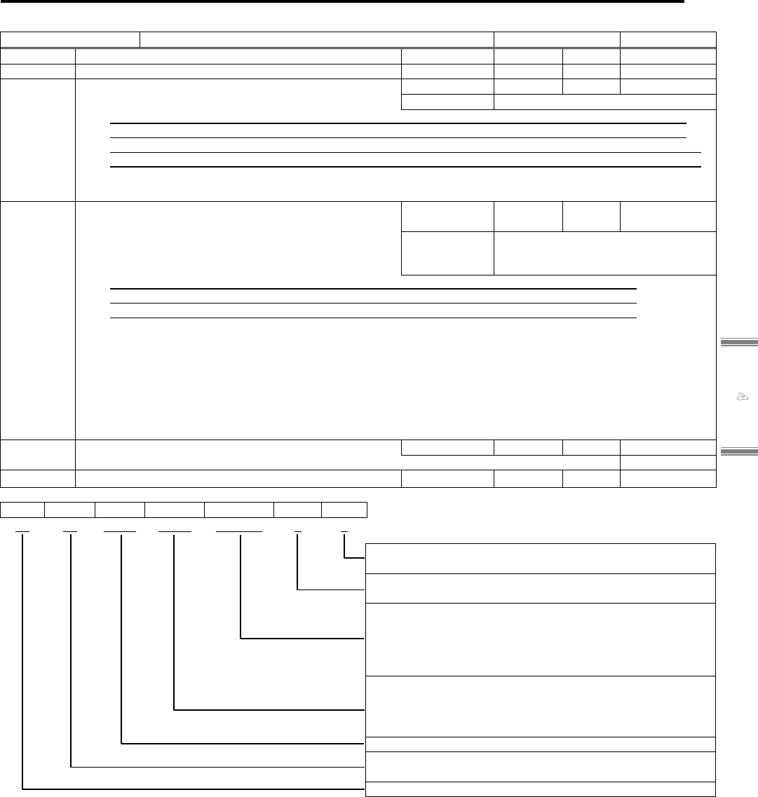
4.2 CoE Communication Area
4-12
4
Ob
j
ect Dictionar
y
0x1C32: SM2 Synchronization (Output Sync Manager Parameter)
Index 0x1C32 SM2 synchronization setup Object Code RECORD
Sub-Idx Name/Description Data Type Access PDO Range
0x00 Number of synchronization parameter Unsigned8 RO No 0x20
0x01 Synchronization Type [SM2TYP]
Sets up synchronous mode.
Unsigned16 RW No 0x0002
Setting Range
0x0000-0x0003
0x00: not synchronized Asynchronized (Free Run)
0x01: Sync Manager2 SM2 Event Synchronization
0x02: DC Sync0 SYNC0 Event Synchronization (Synchronized with SYNC0 Hardware Signal)
0x03: DC Sync1 SYNC1 Event Synchronization (Synchronized with SYNC1 Hardware Signal)
✔ Must set this from controller at communication configuration.
✔ For use of SM2 event sync, communication jitter shall be 6 μs or less.
0x02 Cycle Time: Unit (ns) [SM2SYC]
Sets up communication cycle between master and
slave.
Set Value: When T (ns) =125000x2Y (ns), it is in the
range of Y= 1 to 7.
Unsigned32 RW No 0x0007A120
(500μs)
Setting Range
0x0000F424 - 0x00F42400
(0.0625 - 16ms)
Free Run (Synchronization Type=0x0): Local Timer Event Cycle of Slave
DC SYNC0 (Synchronization Type=0x02): SYNC0 Cycle Time (0x09A0 - 0x09A3)
DC SYNC1 (Synchronization Type=0x03): SYNC1 Cycle Time (0x09A4 - 0x09A7)
Possible Setting Value: T (ns)
62.5μs: 0x0000F424 125μs: 0x0001E848 250μs: 0x0003D090
500μs: 0x0007A120 1ms: 0x000F4240 2ms: 0x001E8480
4ms: 0x003D0900 8ms: 0x007A1200 16ms: 0x00F42400
✔ Error is returned when the value is set except the value that can be set as above.
✔ When 0x01 is set to Synchronization Type, it must set via a controller, at the time of communication
configuration.
0x03 Shift Time: Unit (ns) Unsigned32 RO No 0x0
Time between Hardware Output Effective Operation and Related Event
0x04 Synchronization Type Supported Unsigned16 RO No 0x000F
MSB LSB
Res. Dyna Res. Shift DC Sync Free
15 14 13 - 7 6 5 4 3 2 1 0
bit0 : FreeRun Mode Support
1: FreeRun Mode Support
bit1 : SyncManager Synchronous Support
1: SyncManager 2 Event Sync Support
bit4-2 : DC Type Support
000 : Un-supported
001 : DC SYNC0 Event Sync Support
010 : DC SYNC1 Event Sync Support
100 : Un-supported
bit6-5
: Output Shift Support
00 : Un-supported
01 : Un-supported
10 : Un-supported
bit13-7 : Reserved
bit14 : Dynamic Cycle Time
0 : Un-supported
bit15 : Reserved

4. Object Dictionary
4-13
Sub-Idx Name/Description Data Type Access PDO Range
0x05 Minimum Cycle Time : Unit (ns) Unsigned32 RO No 0x0000F424
(62.5μs)
The minimum cycle time is supported by slave. (Maximum time of local cycle)
0x06 Copy and Operation Time (Calc and Copy Time)
: Unit (ns)
Unsigned32 RO No
0x0000F424
(62.5μs)
Time required of micro controller in order to copy process data to local memory from SyncManager.
Operation is processed, if required before transmitting data to a process.
0x07 Reserved
Unsigned32 - - -
0x08 Get Cycle Time
0: Stops local cycle time measurement.
1: Starts local cycle time measurement.
✔ Measurement value is reset when written into again.
Unsigned16 RW No -
0x09 Delay Time
Unsigned32 RO No
0x00009088
(37μs)
This is hardware delay time of a slave. It is the time from trigger reception of SYNC0 or SYNC1 event to
become effective a value output.
✔ Only for the synchronization type 0x02 (DC Sync0) or 0x03 (DC Sync1).
0x0A
Not supported [Sync0 Cycle Time]
Unsigned32 RW No
-
This is the time between two Sync0 signals, for the case when SYNC0 fixed cycle time is required of
application.
✔ Only the synchronization type 0x02 (SYNC0) or local cycle control.
0x0B Cycle Time Too Small Unsigned16 RO No
-
This error counter is incremented when cycle time is too short as local cycle cannot be completed or input
data cannot prepare by the next SM event.
0x0C SM Event Missed Unsigned16 RO No
-
This error counter is incremented when application demands SM event and cannot receive it. As a result, data
may be unable to be copied any more.
0x0D Shift Time Too Short Unsigned16 RO No
-
This error counter is incremented if the time interval between SYNC0 trigger and an output is too short
according to the fact that shift time or SYNC1 cycle time is too short.
0x0E
Not supported [RxPDO Toggle Failed]
Unsigned16 RO No
-
This error counter is incremented when slave supports an RxPDO toggle and then new RxPDO data cannot
be received from a master. (When RxPDO toggle is set to TRUE.)
0x0F - 0x1F Reserved
- - - -
0x20
Not supported [Sync Error]
BOOL RO Possible
TxPDO mapping is possible at the time of SM-Event Missed or Shift Time Too Short Counter support.
0: No Sync. Error or unsupported Sync.Error
1: Sync. Error

4.2 CoE Communication Area
4-14
4
Ob
j
ect Dictionar
y
0x1C33: SM3 Synchronization (Input SyncManager Parameter)
Index 0x1C33 SM3 Synchronization Object Code RECORD
Sub-Idx Name/Description Data Type Access PDO Initial Value
0x00 Number of Synchronization Parameter Unsigned8 RO No 0x20
0x01 Synchronization Type [SM3TYP]
Unsigned16 RW No 0x0002
Setting Range
0x00, 0x02, 0x03, 0x22
0x00: not synchronized Asynchronized (Free Run)
0x01: Sync Manager2 SM2 Event Synchronization
(In case that Output is not transferred at Safe-OP and OP.)
0x02: DC Sync0 SYNC0 Event Synchronization (Synchronized with SYNC0 Hardware Signal)
0x03: DC Sync1 SYNC1 Event Synchronization (Synchronized with SYNC1 Hardware Signal)
0x04-0x21: Reserved
0x22: Synchron SM2 Event Synchronization
(In case that Output is transferred at Safe-OP and OP.)
✔ Must set this from controller at communication configuration.
✔ For use of SM2 event sync, communication jitter shall be 6 μs or less.
0x02
Cycle Time: Unit (ns) [SM3SYC]
Unsigned32 RO No 0x0007A120
(500μs)
Free Run (Synchronization Type=0x0): Local Timer Event Cycle of Slave
DC SYNC0 (Synchronization Type=0x02): SYNC0 Cycle Time (0x09A0 - 0x09A3)
DC SYNC1 (Synchronization Type=0x03): SYNC1 Cycle Time (0x09A4 - 0x09A7)
✔ The value shall be the same as Index: 0x1C32, Sub-index2.
0x03 Shift Time: Unit (ns) Unsigned32 RO No 0x0
Time between Input Latch Operation from Hardware and Related Operation
✔ The value shall be the same as Index: 0x1C32, Sub-index3.
0x04 Synchronization Type Supported Unsigned16 RO No 0x000F
MSB LSB
Res. Dyna Res. Shift DC Sync Free
15 14
13・・・7
6 5 4 3 2 1 0
bit0 : FreeRun Mode Support
1: FreeRun Mode Support
bit1 : SyncManager Synchronous Support
1: SyncManager 2 Event Sync Support
bit4-2 : DC Type Support
000 : Un-supported
001 : DC SYNC0 Event Sync Support
010 : DC SYNC1 Event Sync Support
100 : Un-supported
bit6-5 : Output Shift Support
00 : Un-supported
01 : Un-supported
10 : Un-supported
bit13-7 : Reserved
bit14 : Dinamic Cycle Time
0 : Un-supported
bit15 : Reserved

4. Object Dictionary
4-15
Sub-Idx Name/Description Data Type Access PDO Range
0x05 Minimum Cycle Time : Unit (ns) Unsigned32 RO No 0x0000F424
(62.5μs)
The minimum cycle time is supported by slave. (Maximum time of local cycle)
✔ The value shall be the same as Index: 0x1C32, Sub-index5.
0x06 Copy and Operation Time (Calc and Copy Time)
: Unit (ns)
Unsigned32 RO No 0x0001E848
(125μs)
Time required from Input Latch through minimum cycle time.
0x07 Reserved
- - - -
0x08 Get Cycle Time
0: Stops local cycle time measurement.
1: Starts local cycle time measurement.
✔ Measurement value is reset when written into
again.
Unsigned16 RW No
-
0x09 Delay Time Unsigned32 RO No
-
This is hardware delay time of a slave. It is the time from trigger reception of SYNC0 or SYNC1 event until
latching input value.
✔ Only for the synchronization type 0x02 (DC Sync0) or 0x03 (DC Sync1).
0x0A
Not supported [Sync0 Cycle Time]
Unsigned32 RW No
-
This is the time between two Sync0 signals, for the case when SYNC0 fixed cycle time is required of
application.
✔ Only the synchronization type 0x02 (SYNC0) or local cycle control.
0x0B Cycle Time Too Small Unsigned16 RO No
-
This error counter is incremented when cycle time is too short as local cycle cannot be completed or input
data cannot prepare by the next SM event.
0x0C SM-Event Missed Unsigned16 RO No
-
This error counter is incremented when application demands SM event and cannot receive it. As a result,
data may be unable to be copied any more.
0x0D Shift Time Too Short Unsigned16 RO No
-
This error counter is incremented if the time interval between SYNC0 trigger and an output is too short
according to the fact that shift time or SYNC1 cycle time is too short.
0x0E Not supported [RxPDO Toggle Failed] Unsigned16 RO No
-
This error counter is incremented when slave supports an RxPDO toggle and then new RxPDO data cannot
be received from a master. (When RxPDO toggle is set to TRUE.)
0x0F:0x1F
Reserved
- - - -
0x20 Not supported [Sync Error] BOOL RO Possible
TxPDO mapping is possible at the time of SM-Event Missed or Shift Time Too Short Counter support.
0: No Sync. Error or unsupported Sync.Error
1: Sync. Error

4.3 Profile Area
4-16
4
Ob
j
ect Dictionar
y
4.3 Profile Area
The followings are shown in Table; profile area of CoE (CANopen over EtherCAT) object list, 3E Model EtherCAT Supported /
Un-supported, Data length, Access (Dir), PDO Mapping, and parameter effective timing (updating).
#=immediately, $=ESM state transition required, and &=effective after control power cycle.
Profile Area (No.1)
○: Support, ●: Support (with limit), □: Support (Not changeable :Fixed Value), ×: Not supported
Index S-Idx FP FV FT FH Name Data Type Dir PDO_M Update
NVRAM
0x6007 0x00 ○ ○
●
○
Abort Connection Option Code
Integer16 RW No # Yes
0x603F 0x00 ○ ○ ○ ○
Error Code
Unsigned16 RO Possible - -
0x6040 0x00 ○ ○ ○ ○ Control Word Unsigned16 RW Possible # -
0x6041 0x00 ○ ○ ○ ○ Status Word Unsigned16 RO Possible
-
-
0x605A 0x00 ○ ○ ○ ○ Quick Stop Option Code Integer16 RW No # Yes
0x605B 0x00 ○ ○
●
○ Shutdown Option Code Integer16 RW No # Yes
0x605C 0x00 ○ ○ ○
○
Disable Operation Option Code Integer16 RW No # Yes
0x605D 0x00 ○ ○ ○ ○ Halt Option Code Integer16 RW No # Yes
0x605E 0x00 ○ ○
○ ○
Fault Reaction Option Code Integer16 RW No
#
Yes
0x6060 0x00 ○ ○ ○ ○ Operation Mode Integer8 RW Possible # Yes
0x6061 0x00 ○ ○ ○ ○ Operation Display Integer8 RO Possible - -
0x6062 0x00 ○ × ×
○
Position Demand Value Integer32 RO Possible
-
-
0x6063 0x00 ○ ○ ○ ○
Internal Actual Position
Integer32 RO Possible - -
0x6064 0x00 ○ ○ ○ ○
Actual Position
Integer32 RO Possible - -
0x6065 0x00 ○ × ×
○
Position Deviation Window
Unsigned32 RW No
#
Yes
0x6067 0x00 ○ × ×
○
Position Window
(Positioning complete range)
Unsigned32 RW No # Yes
0x6068 0x00 □ × ×
□
Position Window Time
Unsigned16 RW No - -
0x6069 0x00 ○ ○ ×
○
Actual Velocity Sensor Value
Integer32 RO Possible - -
0x606A 0x00 □ □ □ □
Sensor Selection Code
Integer16 RW No
-
-
0x606C 0x00
○
○ ×
○
Actual Velocity Value (Velocity Monitor)
Integer32 RO Possible - -
0x606D 0x00 × ○ × ×
Velocity Window (Velocity matching range)
Unsigned16 RW No # -
0x606E 0x00 × ○ × × Velocity Window Time Unsigned16 RW No # -
0x606F 0x00 × ○ × × Velocity Threshold Unsigned16 RW No # -
0x6070 0x00 × ○ × × Velocity Threshold Time Unsigned16 RW No # -
0x6071 0x00 × × ○ ×
Target Torque (force)
(Torque (force) Command)
Integer16 RW Possible # -
0x6072 0x00 ○ ○ ○ ○
Maximum Torque (force)
(Torque (force) Limit)
Unsigned16 RW Possible # -
0x6076 0x00 ○ ○ ○ ○ Motor Rating Torque (force) Unsigned32 RO No
-
-
0x6077 0x00 ○ ○ ○ ○
Actual Torque (force) Value
(Torque (force) Monitor)
Integer16 RO Possible - -
0x6078 0x00 ○ ○ ○ ○ Actual Current Value Integer16 RO Possible - -
0x6079 0x00 ○ ○ ○ ○ DC Link Circuit Voltage Unsigned32 RO Possible - -
0x607A 0x00 ○ × × × Target Position (Position Command) Integer32 RW Possible # -
0x607B 0x00 - - - - Position Range Limit Unsigned8 RO No - -
↑ 0x01 ○ × ×
○
Minimum Position Limit Integer32 RW No $ Yes
↑ 0x02 ○ × ×
○
Maximum Position Limit Integer32 RW No $ Yes
0x607C 0x00 ○ ○ ○ ○ Coordinates Offset (Homing Offset) Integer32 RW Possible # Yes
0x607D 0x00
- - - -
Software Position Limit Unsigned8 RO No
-
-
↑ 0x01 ○ × ×
○
Software Minimum Position Limit Integer32 RW No # Yes
↑ 0x02 ○ × ×
○
Software Maximum Position Limit Integer32 RW No # Yes
0x607E 0x00 ○ ○ ○ ○ Polarity Unsigned8 RW No $ Yes
0x607F 0x00 ○ ○ × × Max. Profile Velocity Unsigned32 RW Possible # Yes
0x6081 0x00 ○ ○ × × Profile Velocity Unsigned32 RW Possible # -
0x6083 0x00 ○ ○ × ×
Profile Acceleration (Accelerating Constant)
Unsigned32 RW Possible # Yes
0x6084 0x00 ○ ○ × ×
Profile Deceleration (Decelerating Constant)
Unsigned32 RW Possible # Yes
0x6085 0x00 ○ ○
●
○ Quick Stop Deceleration Unsigned32 RW Possible # Yes
0x6086 0x00 ○ × × × Motion Profile Type Integer16 RW Possible # -
0x6087 0x00 × × ○ × Torque (force) Slope Unsigned32 RW Possible # -
0x6088 0x00 × × □ × Torque (force) Profile Type Integer16 RW Possible
#
-
0x608F 0x00
- - - -
Position Encoder Resolution
(Encoder Resolution)
Unsigned8 RO No
-
-
↑ 0x01
○ ○ ○ ○
Position Encoder Resolution
Unsigned32 RW No
$
-
↑ 0x02
○ ○ ○ ○
Motor axis rotation number
Unsigned32 RW No
$
-

4. Object Dictionary
4-17
Profile Area (No.2)
Index S-Idx FP FV FT FH Name Data Type Dir PDO_M Update
NVRAM
0x6091 0x00
- - - - Gear Ratio Unsigned8 RO No - -
↑ 0x01
○ ○ ○ ○
Motor Shaft Resolution Unsigned32 RW No
$
-
↑ 0x02
○ ○ ○ ○
Drive Shaft Resolution Unsigned32 RW No
$
-
0x6092 0x00
- - - -
Feed Constant Unsigned8 RO No
-
-
↑ 0x01
○ ○ × ○
Feed (Travel Distance) Unsigned32 RW No
$
-
↑ 0x02
○ ○ × ○
Feed Shaft Resolution Unsigned32 RW No
$
-
0x6098 0x00 × × × ○ Homing Method Integer8 RW Possible # Yes
0x6099 0x00
- - - - Homing Velocity Unsigned8 RO No - -
↑ 0x01 × × × ○ Home Switch Searching Velocity Unsigned32 RW Possible # Yes
↑ 0x02 × × × ○ Zero Phase Searching Velocity Unsigned32 RW Possible # Yes
0x609A 0x00 × × × ○ Homing Acceleration Unsigned32 RW Possible # Yes
0x60A3 0x00 ○ × × ×
Profile Jerk Use Unsigned8 RW No
#
-
0x60A4 0x00
- - - - Profile Jerk Unsigned8 RO No - -
↑ 0x01 ○ × × × Profile Jerk 1 Unsigned32 RW No # -
↑ 0x02 ○ × × × Profile Jerk 2 Unsigned32 RW No # -
0x60A8 0x00 ○ × × ○ SI unit system for position Unsigned32 RW No # Yes
0x60B0 0x00 ○ × × × Position Offset (Position Addition) Integer32 RW Possible # -
0x60B1 0x00 ○ ○
-
×
Speed Offset (Speed Addition) Integer32 RW Possible # -
0x60B2 0x00 ○ ○ ○ ×
Torque (force) Offset
(Torque (force) Addition)
Integer16 RW Possible # -
0x60B8 0x00
○ ○ ○ ●
Touch Probe Function Unsigned16 RW Possible # -
0x60B9 0x00
○ ○ ○ ●
Touch Probe Status Unsigned16 RO Possible # -
0x60BA 0x00
○ ○ ○ ●
Touch probe1 positive edge position stored
Integer32 RO Possible # -
0x60BB 0x00
○ ○ ○ ●
Touch probe1 negative edge position stored
Integer32 RO Possible # -
0x60BC 0x00
○ ○ ○ ●
Touch probe2 positive edge position stored
Integer32 RO Possible # -
0x60BD 0x00
○ ○ ○ ●
Touch probe2 negative edge position stored
Integer32 RO Possible # -
0x60C0 0x00 ○ × × ×
Interpolation sub mode select Integer16 RW No
#
-
0x60C1 0x00
- - - - Interpolation data record Unsigned8 RO No - -
↑ 0x01 ○ × × × Interpolated position command Integer32 RW Possible # -
↑ 0x02 ○ × × × Interpolation time Unsigned8 RW Possible # -
0x60C2 0x00
- - - - Interpolation time cycle Unsigned8 RO No - -
↑ 0x01 ○
× × ×
Interpolation time unit Unsigned8 RW No
#
-
↑ 0x02 ○
× × ×
Interpolation time exponent Integer8 RW No
#
-
0x60C4 0x00
- - - - Interpolation data configuration Unsigned8 RO No - -
↑ 0x01 ○ × × ×
Maximum buffer size Unsigned32 RO No - -
↑ 0x02 ○ × × × Actual buffer size for interpolation data Unsigned32 RW No # -
↑ 0x03 ○ × × × Interpolation data buffer structure Unsigned8 RW No # -
↑ 0x04 ○ × × × Point of buffer Unsigned16 RW Possible # -
↑ 0x05 ○ × × ×
Data size of interpolation data record Unsigned8 RO No
-
-
↑ 0x06 ○ × × ×
Clear buffer Unsigned8 WO Possible
-
-
0x60C5 0x00 × ○ × × Maximum Acceleration Unsigned32 RW Possible
#
Yes
0x60C6 0x00 × ○ × × Maximum Deceleration Unsigned32 RW Possible
#
Yes
0x60E0 0x00 ○ ○ ○ ○ Positive Torque (force) Limit Value Unsigned16 RW Possible # Yes
0x60E1 0x00 ○ ○ ○ ○ Negative Torque (force) Limit Value Unsigned16 RW Possible # Yes
0x60E3 0x00 - - - -
Support Homing Method
Unsigned8 RO No - -
↑
0x01-
0x25
× × × ○ Support Homing Method 1 - 37 Integer8 RO No - -
0x60F2 0x00 ○ × ×
○
Position Option Code Unsigned16 RW Possible # -
0x60F4 0x00 ○ × ×
○
Actual Position Deviation
(Following Error Actual Value)
Integer32 RO Possible - -
0x60FA 0x00 ○ × ×
○ Control Effort Integer32 RO Possible - -
0x60FC 0x00 ○ × ×
○
Internal Position Command Value Integer32 RO Possible
-
-
0x60FD 0x00 ○ ○ ○ ○
Digital Input Unsigned32 RO Possible - -
0x60FE 0x00
- - - -
Digital Output Unsigned8 RO No
-
-
↑ 0x01 ○ ○ ○ ○ Physical Output Unsigned32 RW Possible # -
↑ 0x02 ○ ○ ○ ○ Bitmask Unsigned32 RW Possible # -
0x60FF 0x00 × ○ × × Target Velocity (Velocity Command) Integer32 RW Possible # -
0x6402 0x00
□ □ □ □ Motor Type Unsigned16 RW Possible - -
0x6403 0x00 ○ ○ ○ ○
Motor Catalog No. VisibleString RO No - -
0x6404 0x00 ○ ○ ○ ○
Motor Manufacturer VisibleString RO No - -
0x6405 0x00 ○ ○ ○ ○
http Motor Catalog Address VisibleString RO No
-
-
0x6502 0x00 ○ ○ ○ ○
Support Drive Mode Unsigned32 RO No - -
0x6503 0x00 ○ ○ ○ ○
Drive Catalog No. VisibleString RO No - -
0x6505 0x00 ○ ○ ○ ○
http Drive Catalog Address VisibleString RO No - -

4.3 Profile Area
4-18
4
Ob
j
ect Dictionar
y
4.3.1 Parameter detail of object group following 0x6000
0x6007: Abort Connection Option Code
Index 0x6007
When an abnormality occurs in the communication system
(Ex. communication timeout, Link lost etc.), This object
indicates how the servo amplifier to behave.
Object Code VARIABLE
Sub-Idx Description Data Type Access PDO Initial Value
0x00 Abort Connection Option Code
Integer16 RW No 0x0001
Setting Range
0x0000-0x0003
# Profile Position (pp), Cyclic Sync Position (csp), Interpolated Position (ip) mode
# Cyclic Sync Velocity (csv), Profile Velocity (pv), Homing (hm) mode
0: No Action (Current limit stop without alarm)
1: Fault Signal (It stops according to Fault Reaction Option Code)
2: Disable Voltage Command (It stops according to Disable Operation Option Code setting) ※
3: Setting prohibited
# Cyclic Sync Torque (Force) (cst), Torque Profile (tq) mode
0: No Action (Current zero stop without alarm)
1: Fault Signal (It stops according to Fault Reaction Option Code)
2: Disable Voltage Command (It stops according to Disable Operation Option Code setting) ※
3: Setting prohibited
✔ It may not stop according as settings if communication data changes to unexpected value before detecting
communication system error.
0x603F: Error code
Index 0x603F Displays codes of errors occurred in the servo amplifier. Object Code VARIABLE
Sub-Idx Description Data Type Access PDO
Initial Value
0x00 Error codes [ERRCODE] Unsigned16 RO Possible 0x0000
Display range
0x0000-0xFFFF
✔ Represents the same information as lower 16-bit of Sub-index 0x01 in pre-defined error field 0x1003 in
CANopen communication method.

4. Object Dictionary
4-19
0x6040: Control Word
Index 0x6040
Indicates reception command of FSA (State Machine) that
PDS (Power Device System) is controlled.
Object Code VARIABLE
Sub-Idx Description Data Type Access PDO
Initial Value
0x00 Control Word [CWORD]
Bit pattern (Bit 7, 3, 2, 1, 0) of Control Word
The composition is as follows.
Unsigned16 RW Possible 0x0000
Display range
0x0000-0xFFFF
Each bit allocation of Control Word
bit15 bit14 bit13 bit12 bit11 bit10 bit9 bit8
Manufacturer Specific Reserved
Operation mode
Specific
Halt
bit7 bit6 bit5 bit4 bit3 bit2 bit1 bit0
Fault
Reset
Operation mode Specific
Enable
Operation
Quick
Stop
Enable
Voltage
Switch
On
Bit9, 6, 5 and 4 are Operation Mode Specification. Halt functional operation of Bit8 is also Operation Mode
Specification. Motion under command is interrupted when Bit8 =1. Slave is defined by Halt option code and
operated.
Since Bit10 is reserved, set to "0". Bit15 to 11 are Manufacturer Specification.
MSB LSB
Manufacturer
Specific
Reserved
Operation mode
Specific
Halt
Fault
reset
Operation mode
Spacific
Enable
operation
Quick
stop
Enable
voltage
Switch
on
15 ・・・ 11 10 9 8
7
6 ・・・ 4 3 2 1 0
Command
Control Word bit
Transition
No.
bit7 bit3 bit2 bit1 bit0
Shut down 0 x 1 1 0 2,6,8
Switch On 0 0 1 1 1 3
Switch On+Enable operation 0 1 1 1 1 3+4
※
1)
Disable voltage 0 x x 0 x 7,9,10,12
Quick Stop 0 x 0 1 x 7,10,11
Disabled operation 0 0 1 1 1 5
Enable operation 0 1 1 1 1 4,16
Fault reset 0→1 x x x x 15
※1) When Switch On and Enable operation are simultaneously received from master, after performing the
"Switch On" function, shifts to "Enable operation" automatically.

4.3 Profile Area
4-20
4
Ob
j
ect Dictionar
y
Allocation of Control Word (manufacturer specific area)
bit15 bit14 bit13 bit12 bit11
Cseten Reserved Reserved Eclr Reserved
MSB LSB
Cseten Resrved Eclr Reserved Reserved
Operation
mode
Spacific
Halt Fr※
Operation
mode
Spacific
Hs※ qs※ ev※ so※
15 14,13 12 11 10 9 8 7
6・・・4
3 2 1 0
bit12: Encoder clear enabled
This Bit 12 performs encoder clearing to absolute encoder. It brings clearing multi-turn info (Multi-turn clear)
and Battery malfunction.
Note) When Position Polarity is reversed (0x607E: bit7=0), the actual position will be within minus one
rotation.
Encoder clearing sequence is shown below.
Shared parts with the entire operating mode in manufacturer specific area for status words are
described below.
bit12: Encoder clear enable [ECLR]
Clears absolute encoder battery malfunction or multiple rotating
positions.
"0": Encoder clear disable "1”: Encoder clear enable
bit15: Magnetic pole position estimation enabled [CSET]
Magnetic pole position estimation command when using linear motor
without hall effect sensor input.
"0": Magnetic pole position estimation disabled
"1": Magnetic pole position estimation enabled
Actual position
recalculate process
0x6040 Control Word
Bit12: ECLR
0x2100 Status Word 1
Bit3: ECLRM
1
0
1
0
0x6064 Actual Position
Undefined
Completion of Encoder clear
Encoder clear
acknowledgement
8ms (max)
200ms or more

4. Object Dictionary
4-21
0x6041: Status Word
Index 0x6041
Indicates status of FSA (State Machine) that PDS (Power Device System) is
controlled.
Object code VARIABLE
Sub-Idx Description Data Type Access PDO
Initial value
0x00 Status Word [STSWORD]
Status list for bit pattern (Bit 6, 5, 3, 2, 1, 0) of Control Word
Unsigned16 RO Possible 0x0000
Display range 0x0000-0xFFFF
Bit allocation of Status Word
bit15 bit14 bit13 bit12 bit11 bit10 bit9 bit8
Reserved
(
Manufacturer Specific)
Reserved
(
Operation mode
Specific
)
Targ et
Value
Ignored
Internal
Limit
Active
Targ et
reached
Remote
Reserved
(
Manufacturer
Specific)
bit7 bit6 bit5 bit4 bit3 bit2 bit1 bit0
Warning
Switch On
Disabled
Quick
Stop
Voltage
Enabled
Fault
Operation
Enabled
Switched
On
Ready to
Switch on
In each state, it is shown by the bit pattern of Status Word indicating current status.
MSB LSB
Manufac
-turer
Specific
Operation
mode
Specific
Internal
Limit
Active
Target
reached
Remote
Manufac
-turer
Specific
Warning
Switch
on
disabled
Quick
stop
Voltage
Enabled
Fault
Operation
enabled
Switch
on
Ready to
switch on
15,14 13 12 11 10 9 8 7
6
5 4 3 2 1 0
No. FSA state
Status Word bit
bit6 bit5 bit3 bit2 bit1 bit0
[A] Not ready to Switch on 0 x 0 0 0 0
[B] Switch on Disabled 1 x 0 0 0 0
[C] Ready to Switch on 0 1 0 0 0 1
[D] Switch on 0 1 0 0 1 1
[E] Operation enabled 0 1 0 1 1 1
[F] Quick stop active 0 0 0 1 1 1
[G] Fault reaction active 0 x 1 1 1 1
[H] Fault 0 x 1 0 0 0
bit4 :Voltage Enabled (Main Circuit Established Status) "1" means that main circuit power supply is impressed.
bit5 :Quick Stop (Quick Stop) "0" means it is under operation by Quick Stop Request
bit7 :Warning (Warning Status) It is set to "1" when warning is occurring in slave.
bit9 :Remote (Control Word Remote)
Operation through EtherCAT communication is enabled at the time of "1".
Operation through EtherCAT communication is disabled at the time of "0", caused by JOG operation via the
setup software.
bit10 :Target reached
It is set to "1" when an operation mode is changed.
It is set to "1" when Quick stop operation is finished and motor stops with Quick stop Option Code; 5 to7.
Besides, when Bit10 (Target reached) of status word is "1", indicates that the motor reached the preset value.
Then cleared to "0" when target position is changed. (Only Profile Position (pp): Reserved)
bit11 :Internal Limit Active
When target position is outside of range, and at invalid, soft limit etc, it is set to "1". Setting range is based on
specification.
Bit13 and 12 are based on operation mode specifications, and Bit15, 14 and 8 are maker specifications.
Allocation for Status Word (manufacturer specific area)
bit15 bit14 bit8
Csetfix Csetpro Reserved
These words are displayed in the status word bit patterns indicating current state in each state.
MSB LSB
Csetfix Csetpro
Operation
mode
Specific
Operation
mode
Specific
Internal
Limit
active
Tr Rm Reserved W Sod
※
Qs
※
Ve F
※
Oe
※
So
※
Rtso
※
15 14 13 12 11 10 9 8 7 6 5 4 3 2 1 0
bit15-14: :Magnetic pole position estimation status [CSETSTS]
The following are linear motor magnetic pole position estimation status.
Bit15 Bit14
0 0 : Magnetic pole position estimation disabled
0 1 : Magnetic pole position estimation in process
1 1 : Magnetic pole position estimation completed 了

4.3 Profile Area
4-22
4
Ob
j
ect Dictionar
y
0x605A: Quick Stop Option Code (EMR)
Index 0x605A
Sets action for stopping motor when quick stop (EMR) command is
inputted.
Object Code VARIABLE
Sub-Idx Description Data Type Access PDO
Initial value
0x00 Quick Stop Option Code [QSTOP]
✔ Treates in the amplifier internally as shown below, depending
on control mode.
-128 to-1, 4, 8 to 127 are reserved. Not possible to be set.
Integer16 RW No 0x0002
Setting Range
0x0000-0x0007
(0 - 7)
# Profile position (pp), Cyclic sync position(csp), Interpolated Position (ip) mode
# Cyclic sync velocity (csv), Profile velocity (pv), Homing (hm) mode
0 : Drive function is Disabled. (To Switch On Disabled after motor stop by dynamic brake operation)
1 : To Switch On Disabled after stop at profile deceleration (0x6084)
2 : To Switch On Disabled after stop at quick stop deceleration (0x6085)
3 : To Switch On Disabled after stop by Current Limit
5-7 : Setting prohibited
# Cyclic Sync Velocity (csv), Profile Velocity (pv) mode
0 : Drive function is Disabled. (To Switch On Disabled after motor stop by dynamic brake operation)
1 : To Switch On Disabled after stop at profile deceleration (0x6084)
2 : To Switch On Disabled after stop at quick stop deceleration (0x6085)
3 : To Switch On Disabled after stop by Current Limit
5 : To Quick Stop Active state after stop at profile deceleration (0x6084)
6 : To Quick Stop Active state after stop at quick stop deceleration (0x6085)
7 : To Quick Stop Active state after stop by Current Limit
# Cyclic sync torque (force) (cst), Torque (force) profile (tq) mode
0 : Drive function is disabled (After a motor stops by dynamic brake operation, Switch On Disabled)
1, 2, 3 : Setting prohibited
5, 6 : Quick Stop Active state after Stops by 0x6087(Torque (force) Slope)
7 : Quick Stop Active state after stop by Current Zero
✔ At the time of stop by the Quick Stop Deceleration (0x6085), it is limited with the minimum value from within
Maximum torque (force) (0x6072), Clockwise side torque (force) limit (0x60E0) and Counterclockwise torque
(force) limit (0x60E1).
✔ At the time of stop by Current Limit, it is limited with the Sequence Current Limit Value (0x201E).
✔ When external EMR signal is input through I/O, it will be "Switch On Disable" even if "Quick Stop Active" is set.
0x605B: Shutdown Option Code
Index 0x605B
Sets how it operates when shifts from Operation Enabled to
the Ready to Switch On State.
Object Code VARIABLE
Sub-Idx Description Data Type Access PDO
Initial value
0x00 Shutdown Option Code Integer16 RW No 0x0000
Setting Range
0x0000-0x0001 (0 – 1)
# Profile position (pp), Cyclic sync position(csp), Interpolated Position (ip) mode
# Cyclic sync velocity (csv), Profile velocity (pv), Homing (hm) mode
0 : Disable Drive: Servo OFF (Motor stop with dynamic brake)
1 : Servo OFF after deceleration stop with profile deceleration (0x6084).
# Cyclic sync torque (force) (cst), Torque (force) profile (tq) mode
0 : Disable Drive: Servo OFF (Motor stop with dynamic brake)
1 : Servo OFF after deceleration stop with torque (force) slope (0x6087)

4. Object Dictionary
4-23
0x605C: Disable Operation Option Code
Index 0x605C
Sets how it operates when shifts from Operation Enabled to
the Switch On State.
Object Code VARIABLE
Sub-Idx Description Data Type Access PDO
Initial value
0x00 Disable Operation Option Code [DISOP] Integer16 RW No 0x0000
Setting Range
0x0000-0x0001 (0 – 1)
Sets how to stop a motor at shifts from servo ON to servo OFF.
# Profile position (pp), Cyclic sync position(csp), Interpolated Position (ip) mode
# Cyclic sync velocity (csv), Profile velocity (pv), Homing (hm) mode
0 : Disable Drive (Motor stop with servo brake) (Current limit stop)
1 : Deceleration stop with profile deceleration (0x6084).
# Cyclic sync torque (force) (cst), Torque (force) profile (tq) mode
0 : Disable Drive (Motor stop with servo brake) (Current zero stop)
1 : Deceleration stop with torque (force) slope (0x6087)
✔ When main circuit power is shut down, emergency stop (dynamic brake) operation performed regardless of
setting.
✔ In case that torque slope is selected at torque control (cst or tq), amplifier internal delay time to servo off will
be up to 1 second.
To perform slope stop, slope value shall be decided so as to the time to torque command zero is 1 second or
less.
It will be servo off if motor velocity becomes Zero speed range (0x2020) or less when slope stop is used.
✔ In case that zero is set to bit 0 to bit 3 of control word, it stops according to the setting of Disable Option
Code.

4.3 Profile Area
4-24
4
Ob
j
ect Dictionar
y
0x605D: Halt option code
Index 0x605D Sets how it operates when halt bit is set to the control word. Object Code VARIABLE
Sub-Idx Description Data Type Access PDO
Initial value
0x00
Halt option code
✔ Treates in the amplifier internally as shown below,
depending on control mode.
-128 to-1, 4, 8 to 127 are reserved. Not possible to be set.
Integer16 RW No 0x0001
Setting Range
0x0001-0x0003 (1 – 3)
# Profile position (pp), Cyclic sync velocity (csv), Profile velocity (pv), Homing (hm) mode
1 : Operation enabled state after Stop at profile deceleration (0x6084)
2 : Operation enabled state after stop at quick stop deceleration (0x6085)
3 : To Switch On Disabled after stop by Current Limit
✔ If in the profile position (pp) mode or homing mode, set a new setpoint at a restarting after halt release, and
then set "NewSetpoint".
# Cyclic sync position mode (csp), Interpolated Position (ip) mode
1, 2, 3 : Operation enabled state after stop by Current Limit
# Cyclic sync torque (force) (cst), Torque (force) profile (tq) mode
1, 2 : Operation enabled state after Stops by 0x6087(Torque (force) Slope)
3 : Operation enabled state after stop by Current Zero
✔ If servo OFF is desired after stopping with the halt state, servo OFF with set of halt bit of the control word is
required.
0x605E: Fault Reaction Option Code
Index 0x605E
Sets how it operates when alarm is generated with servo
amplifier.
Object Code VARIABLE
Sub-Idx Description Data Type Access PDO
Initial value
0x00 Fault Reaction Option Code Integer16 RW No 0x0002
Setting Range
0x0000-0x0003 (0-3)
# Profile Position (pp), Interpolated Position (ip), Cyclic Sync Position (csp) mode
# Profile Velocity (pv), Homing (hm), Cyclic Sync Velocity (csv) mode
0 : Drive function is Disabled. (Motor stop by dynamic brake operation)
1 : Stops at profile deceleration (0x6084)
2 : Stops at quick stop deceleration (0x6085)
3 : Stops by Current Limit
✔ It stops by current limit against dynamic brake overheat alarm.
# Torque Profile (tq, Cyclic Sync Torque (cst) mode
0 : Drive function is Disabled. (Motor stop by dynamic brake operation)
1, 2 : Setting prohibited
3 : Current zero stop
✔ It stops by current zero against dynamic brake overheat alarm.
✔ Due to alarm cause, it stops by dynamic brake operation regardless of setting.
Refer to M0011696 chapter 8 Maintenance, for alarm cause of dynamic brake stop.
If main circuit power is shutdown during operation of any option codes, it stops by emergency stop (dynamic brake)
operation regardless of setting.

4. Object Dictionary
4-25
0x6060: Operation Mode
Index 0x6060 Indicates requested operation mode. Object Code VARIABLE
Sub-Idx Description Data Type Access PDO
Initial value
0x00 Operation Mode [OPMODE]
0 : No Mode/Mode is not assigned.
1 : (pp) Profile Position mode
2 : Reserved
3 : (pv) Profile Velocity mode
4 : (tq) Torque (force) Profile mode
5 : Reserved
6 : (hm) Homing mode
7 : (ip) Interpolated Position mode
8 : (csp) Cycle Sync. Position mode
9 : (csv) Cycle Sync. Velocity mode
10 : (cst) Cycle Sync. Torque (force) mode
Integer8 RW Possible 0x00
Setting Range
0x00-0x0A
(0 – 10)
✔ When this parameter is read, "operation mode" already set is read out.
Operation mode while actual operation serves as "Operation Mode Display" (0x6061).
✔ Mode change is not available during motor rotation. Change this parameter at the time of the
main power supply OFF, Servo-off, or motor stop.
✔ Servo ON is not available when Operation Mode is set “0”.
0x6061: Operation Mode Display
Index 0x6061
Indicates actual operation mode.
Definition is the same as 0x6060: Operation Mode.
Object Code VARIABLE
Sub-Idx Description Data Type Access PDO
Initial value
0x00
Operation Mode Display [OPDISP]
0 : No Mode/Mode is not assigned.
1 : (pp) Profile Position mode
2 : Reserved
3 : (pv) Profile Velocity mode
4 : (tq) Torque (force) Profile mode
5 : Reserved
6 : (hm) Homing mode
7 : (ip) Interpolated Position mode
8 : (csp) Cycle Sync. Position mode
9 : (csv) Cycle Sync. Velocity mode
10 : (cst) Cycle Sync. Torque (force) mode
Integer8 RO Possible 0x00
Display Range
0x00-0x0A
(0 – 10)
It is not changed until motor stop even if operation mode changed during motor rotation.
0x6060
Operation Mode
Volocity
0x6061
Operation Mode Display
0x6041 Status Word
Bit10: Target Reached
Mode change
Request
Mode change
Request
ZVDAT
1
0

4.3 Profile Area
4-26
4
Ob
j
ect Dictionar
y
0x6062: Position Demand Value
Index 0x6062 Indicates the internal target position. Object Code VARIABLE
Sub-Idx Description Data Type Access PDO
Initial value
0x00 Target position [PDemand]
Indicates the internal position command at position control
mode.
This position command updates with the servo control
cycle 125μs.
Integer32 RO Possible
-
Display Range
0x80000000-0x7FFFFFFF
(-2147483648 to 2147483647)
Unit
UP (User Position unit)
0x6063: Internal Actual Position
Index 0x6063 Indicates real position of motor encoder. Object Code VARIABLE
Sub-Idx Description Data Type Access PDO
Initial value
0x00 Internal Actual Position [IACPMON]
Internal actual position data update by the servo control
cycle 125μs.
Monitor unit indicates the resolution of motor encoder to
be used.
Integer32 RO Possible
-
Display Range
0x80000000-0x7FFFFFFF
(-2147483648 to 2147483647)
Unit
Pulse
✔ Encoder combination: In the case of Absolute encoder
Effective bit length=Multiply single turn resolution by mult-turn bit.
The bit except effective bit length becomes "x" (undefined).
✔ Encoder combination: In the case of Incremental encoder
Indicates the value of 4-multiplied A/B signals via 32-bit up/down freerun counter which is to be zero count when
control power turns ON.
✔ If the 0x607E position polarity (bit7) = 1, this data is inverted. Therefore, From an anterior view of the motor the
value increases in the direction of Counter-Clockwise rotation (CCW).
0x6064: Position Actual Value
Index 0x6064
Indicates after offset process or the actual position of motor
encoder.
Object Code VARIABLE
Sub-Idx Description Data Type Access PDO
Initial value
0x00 Position Actual Value [APMON]
Indicates present position
In case of synchronization by distributed clock
(0x1C32-01 is DC Sync0 or DC Sync1), present position
data that is latched by SYNC signal will reply.
Integer32 RO Possible
-
Display Range
0x80000000-0x7FFFFFFF
(-2147483648 to 2147483647)
Unit
UP (User Position unit)
In case of asynchronization system, latest present position will reply.
✔ Encoder combination: In the case of Incremental encoder
Indicates the value of 4-multiplied A/B signals via 32-bit up/down freerun counter which is to be zero count when
control power turns ON.
From an anterior view of the motor the value increases in the direction of Clockwise rotation (CW), when
positive (+) polarity command.
✔ When the position polarity of 0x607E is reversed, the value increases in the CCW direction.
0x6065: Position Deviation Window (Position Deviation Counter Overflow Value)
Index 0x6065
Permissible position range is set as a position request value
relatively to.
Object Code VARIABLE
Sub-Idx Description Data Type Access PDO
Initial value
0x00 Position Deviation Window [OFLV]
When position actual value crosses position deviation
window, becomes Excessive position deviation alarm.
|Position Actual Value Deviation| >= Set Value
Unsigned32 RW No 0x4C4B40
(5000000)
Setting Range
0x00000001-0x7FFFFFFF
(1 to 2147483647)
Unit UP (User Position unit)

4. Object Dictionary
4-27
0x6067: Position Window (Positioning completion range)
Index 0x6067
Sets up the range permissible as target position attainment.
When position actual value of position encoder is in Position
Window, means arriving at target position.
Object Code VARIABLE
Sub-Idx
Description
Data Type
Access PDO
Initial value
0x00 Position Window [INP]
When position deviation counter value is below this
preset value, outputs IN-Position signal (INP).
When |Position Actual Value Deviation|<= Set Value,
outputs Position Window Monitor (INP monitor).
Unsigned32
RW No 0x64
(100)
Setting Range
0x00000000-0x7FFFFFFF
(0 to 2147483647)
Unit
UP (User Position unit)
◆In the case of incremental encoder, 4 times of the number of encoder pulses are standard.
◆In the case of absolute encoder, absolute value is standard.
0x6068: Position Window Time
Index 0x6068
Sets up time until outputs to INP monitor after arriving in
Position Window.
Object Code
VARIABLE
Sub-Idx
Description
Data Type
Access
PDO
Initial value
0x00 Position Window Time
This servo amplifier is outputted immediately after
arriving in setting range.
Unsigned16 RW No 0x0000
Setting Range
0x0000-0x0000
Unit ms
0x6069: Actual Sensor Velocity
Index 0x6069 Indicates actual value of velocity sensor.
Object Code
VARIABLE
Sub-Idx
Description
Data Type
Access
PDO
Initial value
0x00 Actual Value of Velocity Sensor
Indicates actual velocity calucurated by position loop
encoder.
✔ Outputs same data with 0x606C.
Integer32 RO Possible -
Display Range
0x80000000-0x7FFFFFFF
(-2147483648 to 2147483647)
Unit UP (User Position unit) / s
0x606A: Sensor Selection Code
Index 0x606A
Selects the source of velocity sensor actual value.
It determines whether a differentiated position signal or the signal
from a separate velocity sensor.
Object Code
VARIABLE
Sub-Idx
Description
Data Type
Access
PDO
Initial value
0x00 Sensor Selection Code
0: Actual velocity from position encoder
1: Actual velocity from velocity encoder
Integer16 RW No 0x0000
Setting Range
0x0000-0x0001
Position encoder and velocity encoder use the same encoder.
0x606C: Velocity Actual Value
Index 0x606C
It has actual velocity value calculated from position encoder.
Value shall be given in the velocity unit of user definition.
Object Code
VARIABLE
Sub-Idx
Description
Data Type
Access
PDO
Initial value
0x00 Velocity Actual Value [ACVMON]
✔ Filter is processed to data, and cutoff frequency is
250Hz.
Integer32 RO Possible -
Display Range
0x80000000-0x7FFFFFFF
(-2147483648 to 2147483647)
Unit UP (User Position unit) /s
Position command pulse
frequency monitor
In-Position Window
Set Value
1 INP
0 1
Position Deviation Monitor

4.3 Profile Area
4-28
4
Ob
j
ect Dictionar
y
0x606D: Velocity Window (Velocity Matching: Rotation Speed Setup)
Index 0x606D
Sets the range regarded as velocity match.
Use this setting when “Velocity Matching Unit Selection” is
"0x00_UV".
Object Code VARIABLE
Sub-Idx
Description
Data Type
Access
PDO
Initial value
0x00 Velocity Window
When the actual velocity remains within the range of the
target velocity during the time period set in velocity window
time shown in 0x606E, "TargetReached" in the status word
is set. This is enabled in profile velocity mode.
Unsigned16 RW No 0x32
(50)
Setting Range
0x0000-0xFFFF
(0 to 65535)
Unit min
-1
✔ The velocity matching output switches the setting of rotation speed UV) and ratio (%) by Velocity matching unit
output selection (0x20F0.4). At selection of rotation speed setup, the condition under this setting value can be
monitored with the status word (0x6040) bit 10: Target matching monitor.
0x606E: Velocity Window Time
Index 0x606E
After velocity attainment, sets up time (timer) until the status word
“TargetReached” is set.
Object Code
VARIABLE
Sub-Idx
Description
Data Type
Access
PDO
Initial value
0x00 Velocity Window Time
This servo amplifier sets the status word Bit 10: Target
matching monitor when the velocity reaches the setting range
and remains within the range for a time longer than the setting.
Unsigned16 RW No 0x0001
Setting Range
0x0001-0x1388
(1 to 5000)
Unit ms
0x606F: Velocity Threshold (Speed Zero Setting)
Index 0x606F Sets the range regarded as speed zero.
Object Code
VARIABLE
Sub-Idx
Description
Data Type
Access
PDO
Initial value
0x00 Speed Zero Window
When the actual velocity falls below this setting value, the
status word “Speed zero detection” is set.
This is enabled only in profile velocity mode.
Set same value with 0x2020 because of same parameter.
Unsigned16 RW No 0x0032
(50)
Setting Range
0x0005-0x01F4 (5 to 500)
Unit
min
-1
0x6070: Velocity Threshold Time
Index 0x6070
Sets up time (timer) until the status word “Speed zero detection” is
canceled.
Object Code
VARIABLE
Sub-Idx
Description
Data Type
Access
PDO
Initial value
0x00 Velocity Threshold Time
When the actual velocity is higher than the threshold velocity
for a time longer than the setting, the status word bit 12: Speed
zero detection is canceled. This is enabled only in profile
velocity mode.
Unsigned16 RW No 0x0001
Setting Range
0x0001-0x1388
(1 to 5000)
Unit ms
0x6071 Target Torque (force)
Index 0x6071
Torque (force) command value set to torque (force) controls in
Function Torque (force) Mode.
Object Code
VARIABLE
Sub-Idx
Description
Data Type
Access
PDO
Initial value
0x00 Target Torque (force) [TATRQ]
Setting units are defined by Torque scale selection (0x2078).
Integer16 RW Possible 0x0000
Setting Range
0x8000-0x7FFF
(-32768 to 32767)
Unit UT (User Torque unit)
0x2078=0x00 selected: To be unit of 0.1% / LSB.
0x2078=0x01 selected: To be unit of 4096 (0x1000) / TR(100%)
However, it is limited by max torque (force) for the value that exceeds the max torque (force) of the motor.
Velocity
Velocity
command

4. Object Dictionary
4-29
0x6072: Maximum Torque (force)
Index 0x6072
Indicates maximum set value of the torque (force) permitted to
the motor.
Object Code VARIABLE
Sub-Idx Description Data Type Access PDO
Initial value
0x00
Maximum Torque (force) [MAXTRQ]
Setting units are 0.1% LSB in 1/1000 unit of rated
torque (force). However, it is limited by max torque
(force) for the value that exceeds the max torque (force)
of the motor.
Unsigned16 RW Possible 0x1388
(500.0)
Setting Range
0x0000-0x1388 (0 to 500.0)
Unit 0.1 %
0x6076: Rated torque
Index 0x6076 Indicates rated torque of selected motor. Object Code VARIABLE
Sub-Idx Description Data Type Access PDO
Initial value
0x00 Rated torque
Indicates rated torque of selected motor.
Only the Sanyo Denki R series motor is accepted.
Unsigned32 RO No
-
Display Range
0x00000000-0xFFFFFFFF
Unit m N・m
0x6077: Actual Torque (force) Value
Index 0x6077 Indicates actual torque (force) value of motor. Object Code VARIABLE
Sub-Idx Description Data Type Access PDO
Initial value
0x00 Actual Torque (force) Value [ACTMON]
Monitor units are defined by Torque scale selection
(0x2078).
Integer16 RO Possible
-
Display Range
0x8000-0x7FFF (-32768 to 32767)
Unit UT (User Torque unit)
0x6078: Actual Current Value
Index 0x6078 Indicates actual current value of motor. Object Code VARIABLE
Sub-Idx Description Data Type Access PDO
Initial value
0x00 Actual Current Value
Monitor units are defined by Torque scale selection
(0x2078).
Integer16 RO Possible
-
Display Range
0x8000-0x7FFF (-32768 to 32767)
Unit UT (User Torque unit)
0x6079: DC link circuit voltage
Index 0x6079 Indicates main circuit DC voltage of amplifier internal circuit. Object Code VARIABLE
Sub-Idx Description Data Type Access PDO
Initial value
0x00 DC link circuit voltage
✔ Indicates main circuit DC voltage.
Unsigned32 RO Possible
-
Display Range
0x00000000-0xFFFFFFFF
Unit mV
0x607A: Target Position
Index 0x607A
Command position of drive moved by setup of motion control
parameters, such as velocity, acceleration, deceleration, and
motion profile type.
Object Code VARIABLE
Sub-Idx Description Data Type Access PDO
Initial value
0x00 Target Position [TAPOS]
Sets up absolute position command for each
communication cycle.
Integer32 RW Possible 0
Display Range
0x80000000-0x7FFFFFFF
Unit UP (User Position unit)

4.3 Profile Area
4-30
4
Ob
j
ect Dictionar
y
0x607B: Position range Limit (Modulo value)
Index 0x607B
At operation mode of position command inputting system, sets the
position coordinates range able to be set. Both controller (position
command) and driver (actual position) communicate position data
within the range of position coordinates set here.
Object Code
Array
Sub-Idx Name/Description Data Type
Access
PDO
Initial value
0x00 Number of Entry Unsigned8 RO No 0x2
0x01 Position range limit minimum value [MINPLIM] Integer32 RW No 0x80000000
Setting value 0x80000000-0x00000000
0x02 Position range limit maximum value [MAXPLIM] Integer32 RW No 0x7FFFFFFF
Setting value 0x00000000-0x7FFFFFFF
<Description of set value>
- Unit is the same user definition as target position. UP (User Position unit)
- When Position range limit minimum value = 0x00000000 and Position range limit maximum value =0x00000000 are set,
or when Position range limit minimum value = 0x80000000 and Position range limit maximum value =0x7FFFFFFF are set,
the position coordinate is recognized as "Linear coordinate".
- When setting is other than the above, position coordinate indicates "Modulo coordinate". In this case, although the setting
value can be any value, set actual range of motion at no more than the positive maximum value (0x7FFFFFFF) of 32bit
( "position range limit maximum value" - "position range limit minimum value" ≦ 2147483647 (0x7FFFFFFF) )
<Linear coordinate (Straight axis)>
- The limit value of coordinates is the lower limit = 0x80000000, and upper limit = 0x7FFFFFFF. For PP mode, wraparound
exceeding position range limit is available if 0 is set to Min/Max position range limit.
For CSP mode, wraparound at any range limit is available. However, wraparound exceeding limit value with absolute value
command is not available. For CSP mode, wraparound is always available.
To set limits on the range of motion within position range limit, set the appropriate software position limits (0x607D).
< Modulo Coordinate (Rotation Axis) >
- When the current position reaches the position range limit maximum value in the direction of coordinate increase, the
following coordinate value will indicate the setting value of position range limit minimum value
- In the opposite situation, when the current position reaches the position range limit minimum value in the direction of
coordinate decrease, the following coordinate value will indicate the setting value of position range limit maximum value.
- Except for the motion modes listed below in brackets, all position information set by the controllers should be modulo
coordinates.
(In the following case, in the setting of "Standard positioning same as straight axis," for example, if you wish to move from current
position by a value of 90°, the following commands are possible:
"positioning to absolute displacement 630° = 360° (1 revolution) + 270° (in this case, relative displacement of 540°",
"positioning to relative displacement 500° = 360° (1 revolution) + relative displacement of 140 (in the result, positioning to 230°)"
In this case, the current position information always indicates modulo calculated value by 360°.)
- In modulo mode, the parameter to set rotation direction in the profile position mode is 0x60F2 bit7, 6.
Below shows modulo coordinate image of position range limit minimum value=0, and position range limit maximum value=359.
360=0
50330
bit7 bit6
0
0
150210
360=0
50330
bit7 bit6
0
1
150210
360=0
50330
bit7 bit6
1 0
150210
360=0
50330
bit7 bit6
1 1
150210
normal
(similar to linear axis)
only negative
direction
only positive
direction
optimized
(shortest way)
Example of Positioning at Rotation Axis
< Regarding timing in which the setting parameter is reflected to coordinate >
- In the case that the previously set position range limit value has been written in the nonvolatile memory of the servo amplifier
⇒ Immediately after control power is On, the setting value of the position range limit will be reflected on position information.
- In the case that setting of position range limit is changed when ESM is in Pre-Operational status.
⇒ The changed setting value will be reflected when ESM is shifted from Pre-Operational to Safe-Operational.
- In the case that ESM changes setting of position range limit in another status than that of Pre-Operational
⇒ Because the changed setting value will be reflected when ESM is shifted from Pre-Operational to Safe-Operational,
temporarily lower ESM to Pre-Operational and increase ESM again.
< Regarding Modulo value at power on >
- In case of “0” set to bit2 of 0x20F7. (Normal process)
⇒Modulo value is the remainder when encoder position (lower 32 bit) is divided by modulo coordinate.
Modulo value after cycled encoder-coordinate will be different between before and after power cycle, if the remainder is
existed when encoder coordinate is divided by modulo coordinate.
- In case of “1” set to bit2 of 0x20F7. (Special process)
⇒ Recording the modulo value to non-volatile memory at control power off. At power on again, absolute position is checked
and modulo value is calculated even if motor rotates during control power off. When the motor has rotated over the pulse
that calculated with 0x20FC during power off, warning (0x2103-1, bit1=1) will be detected at power on. The modulo value
at that time is different from before power off. Do Homing again and reset the coordinate.

4. Object Dictionary
4-31
0x607C: Home offset (homing mode)
Index 0x607C
Normalizes homing position (mechanical origin) detected in
homing mode by homing offset value.
Object Code VARIABLE
Sub-Idx Description Data Type Access PDO
Initial value
0x00
Home offset [HOFFSET]
# The set homing offset (0x607C) is used to calculate
actual position.
✔ Homing offset can be always written, however, is used
to recalculate only in homing mode.
Integer32 RW Possible 0x00000000
(0)
Setting Range
0x80000000-0x7FFFFFFF
(-2147483648 to 2147483647)
Unit UP (User Position unit)
The actual position (0x6064) using homing position during homing is calculated as follows:
Actual position calculation method (0x20F6-1) = 1 Actual position calculation method (0x20F6-1) = 0
✔ If "ZeroPosition=Home Offset" is required with the other of Homing Method 35 or 37, it shall be set 0x20F6-1 = 1.
0x607D: Software Position Limit
Index 0x607D
Consists of the Maximum / Minimum software position limits. Position command and
actual position are calculated by target position (0x607A) and position offset
(0x60B0) to be limited in absolute position.
Object Code
Array
Sub-Idx Name/Description Data Type Access PDO
Initial value
0x00
Number of Entry
-
RO No 0x2
0x01 Software position limit minimum value [SMINLIM]
Unit is the same user definition as target position. UP
(User Position unit)
Integer32 RW No 0x00000000
(0)
Setting Range
0x80000000-0x7FFFFFFF
0x02 Software position limit maximum value [SMAXLIM]
Unit is the same user definition as target position. UP
(User Position unit)
Integer32 RW No 0x00000000
(0)
Setting Range
0x80000000-0x7FFFFFFF
Since the actually used limit value includes Home Offset (0x607C), it is normalized internally before being
compared with target position.
Normalized Position Limit Minimum Value = Software Position Limit Minimum Value - Home Offset
Normalized Position Limit Maximum Value = Software Position Limit Maximum Value - Home Offset
✔ Function is invalid when the Software Position Limit Minimum Value >= Software Position Limit Maximum Value.
For PP mode, it denys command and doesn't work when the value exceeding a software position limit is set to
target position.
For CSP mode, it stops with command zero at the time target position updated in order is set to out of software
position limit range.
Function is invalid except in position control mode.
Home offset
(0x607C)
Home Position
(Index Pulse)
Actual Position
(0x6064)
Actual Position
(0x6064)
Home offset
(0x607C)
Home Position
(Index Pulse)
A
ctual Position (0x6064)
= Home Position - Home offset (0x607C)
A
ctual Position (0x6064)
= Home Position + Home offset (0x607C)

4.3 Profile Area
4-32
4
Ob
j
ect Dictionar
y
0x607E: Polarity (Position, Velocity, Torque (force) Command/Offset Input Polarity)
Index 0x607E
Sets an input polarity of command.
When Bit=1, the command value is multiplied by -1, and it
serves as a reverse command.
Object Code
VARIABLE
Sub-Idx Description Data Type Access PDO
Initial value
0x00 Polarity [CMDPOL]
Selects the combination of each command polarity
over position command, velocity command, torque
(force) command input, position offset, velocity offset
(velocity addition), and torque (force) offset (torque
(force) addition) from the following contents.
Unsigned8 RW No 0x00
Setting Range
0x00-0xE0
bit7: Position Polarity “0” : Command is multiplied by +1 "1": Multiplied by -1 (Only csp, ip enable)
・Valid only in Cyclic Sync. Position mode (csp) and Interpolated Position mode (ip). When "1" is set,
0x607A Target position and 0x60B0 Position offset input value are multiplied by -1, and command
polarity is reversed.
bit6: Velocity Polarity "0" : Command is multiplied by +1 “1” : Multiplied by -1
・In Cyclic Sync. Position mode (csp) or Interpolated Position mode (ip), when "1" is set, 0x60B0
Velocity offset input value as velocity compensation is multiplied by -1, and compensation polarity is
reversed.
・In Cyclic Sync. Velocity mode (csv), when "1" is set, 0x60FF Target velocity and 0x60B1 Velocity
offset input value are multiplied by -1, and command polarity is reversed.
bit5: Torque (force) Polarity "0" : Command is multiplied by +1 “1” : Multiplied by -1
・In Cyclic Sync. Position mode (csp), Interpolated Position mode (ip) or Cyclic Sync. Velocity mode
(csv), when "1" is set, 0x60B2 Torque (force) offset input value as torque (force) compensation is
multiplied by -1, and compensation command polarity is reversed.
・In Cyclic Sync. Torque (force) mode (cst), when "1" is set, 0x6071 Target torque and 0x6082 Torque
offset input value are multiplied by -1, and command polarity is reversed.
bit4 – 0: Reserved
◆Rotation direction varies as below depends on selection values.
◆ Commad input polarity is set to "Bit7=0, Bit6=0, Bit5=0" as standard,
rotates to negative direction (CCW) by command polarity - / to positive direction (CW) by +.
◆Commad input polarity is set to "Bit7=1, Bit6=1, Bit5=1" as standard,
rotates to positive direction (CW) by command polarity - / to negative direction (CCW) by +.
✔ Changeof this parameter will be impossible if ESM is Operational.
Make sure to perform servo OFF and shift to Pre-Operational, before change.
✔ Refer Linear motor control parameter list for the descriprion of linear motor porality.
✔ If OT is used, set 0x00 or 0xE0.
0x607F: Maximum Profile Velocity
Index 0x607F
Sets permissible maximum velocity for Profile Position
mode.
Object Code
VARIABLE
Sub-Idx Description Data Type Access PDO
Initial value
0x00
Maximum Profile Velocity [VCLM]
Limits maximal allowed profile velocity (0x6081)
during a Profile Position (pp) mode.
✔ The unit is in user definition as same as 0x6081.
Unsigned32 RW Possible 0xFFFFFFFF
Setting Range
0x00000001-0xFFFFFFFF
(1 to 4294967295)
Unit UP (User Position unit) /s

4. Object Dictionary
4-33
0x6081: Profile Velocity
Index 0x6081
Sets attainment velocity after profile acceleration in Profile
Position mode.
Object Code
VARIABLE
Sub-Idx Description Data Type Access PDO
Initial value
0x00 Profile Velocity [PROVEL]
The value is effective for both of CW and CCW.
Unsigned32 RW Possible 0xFFFFFFFF
Display Range
0x00000000-0xFFFFFFFF
(0 to 4294967295)
Unit UP (User Position unit) /s
0x6083: Profile Acceleration
Index 0x6083
Parameters to decide the gradient at the time of motor
acceleration during Profile Position, Function Velocity mode.
Object Code
VARIABLE
Sub-Idx Description Data Type Access PDO
Initial value
0x00 Profile acceleration [TVCACC]
The parameters to give acceleration incline against
preset velocity command, and it set the rate of velocity
per second.
Unsigned32 RW Possible 0xFFFFFFFF
Setting range
0x00000000-0xFFFFFFFF
(0 to 4294967295)
Unit UP (User Position unit) /s
2
✔ This parameter is effective only against Profile Position mode (pp), Profile Velocity mode (pv).
✔ If value is set to “0”, the amplifier proceeds it as "1".
0x6084: Profile Deceleration
Index 0x6084
Parameters to decide the gradient at the time of motor
deceleration during Profile Position, Function Velocity mode.
Object Code
VARIABLE
Sub-Idx Description Data Type Access PDO
Initial value
0x00 Profile Deceleration [TVCDEC]
The parameters to give deceleration incline against
preset velocity command, and it set the rate of
velocity per second.
Unsigned32 RW Possible 0xFFFFFFFF
Setting range
0x00000000-0xFFFFFFFF
(0 to 4294967295)
Unit UP (User Position unit) /s
2
✔ This parameter is effective only against Profile Position mode (pp), Profile Velocity mode (pv). It also used as
deceleration of each option codes for stop.
✔ If value is set to “0”, the amplifier proceeds it as "1".
0x6085: Quick Stop Deceleration
Index
0x6085
Slowdown parameter used for motor stop when quick stop function is
active and "2" or "6" is set to quick stop code object (0x605A). Used also
when Fault reaction code object (0x605E) and the Halt option code
object (0x605D) are "2."
Object Code
VARIABLE
Sub-Idx Description Data Type Access PDO
Initial value
0x00 Quick Stop Deceleration [QSDEC]
The parameters to give deceleration incline against
preset velocity command, and it set the rate of
velocity per second.
Unsigned32 RW Possible 0xFFFFFFFF
Setting range
0x00000000-0xFFFFFFFF
(0-4294967295)
Unit UP (User Position unit) /s
2
✔ If value is set to “0”, the amplifier proceeds it as "1".
1 second
Set value UP/s
0 UP/s
↑
CW
or
CCW
1 second
Set value UP/s
0 UP/s
↑
CW
or
CCW

4.3 Profile Area
4-34
4
Ob
j
ect Dictionar
y
0x6086: Motion Profile Type
Index 0x6086 Motion Profile Type
Object Code
VARIABLE
Sub-Idx Description Data Type Access PDO
Initial value
0x00
Motion Profile Type
Sets the type of motion profile operation.
Unsigned32 RW Possible 0x0000
Setting range
0x0000, 0x0003 (0 or 3)
0x0000: Linear ramp (trapezoid profile)
0x0003: Jerk limited ramp
0x6087: Torque (force) slope
Index 0x6087
Gives an incline to torque (force) command in Torque (force)
profile mode (tq).
Object Code
VARIABLE
Sub-Idx Description Data Type Access PDO
Initial value
0x00
Torque (force) slope [TSLOPE]
Set unit is 0.1% per second.
✔ When Torque (force) slope is set the value more than
maximum current of the motor, it will be limited to
Maximum current.
Unsigned32 RW Possible 0xFFFFFFFF
Setting range
0x00000001-0xFFFFFFFF
Unit 0.1% /s
0x6088: Torque Profile Type
Index 0x6088
This is a parameter to set the Torque (force) Profile Type in
torque (force) profile mode (tq).
Object Code
VARIABLE
Sub-Idx Description Data Type Access PDO
Initial value
0x00 Torque (force) Profile Type
Set unit is fixed to "0 (Linear ramp)".
Integer16 RW Possible
0x0000
Setting range
0x0000-0x0000
0x608F: Position Encoder Resolution
Index 0x608F Sets the resolution of the output shaft encoder.
Object Code
VARIABLE
Sub-Idx Description Data Type Access PDO
Initial value
0x00 Number of entry Unsigned8 RO No 0x02
0x01 Position encoder resolution
Sets the number of pulses of position encoder.
For the time of readout, set value is readout.
Unsigned32 RW No 0x01
Setting range
0x00000001-0xFFFFFFFF
Unit Pulse
0x02 Rotation speed of motor axis
Sets the rotation speed of motor axis.
Since this servo amplifier is not compatible with this
function, values other than 1 cannot be set.
Unsigned32 RW No 0x01
Setting range
0x01-0x01
Unit Rev.
0x6091: Gear Ratio
Index 0x6091 Sets the gear ratio of the motor shaft and the output shaft.
Object Code
VARIABLE
Sub-Idx
Description
Data Type
Access
PDO
Initial value
0x00
Number of entry
Unsigned8
RO No 0x02
0x01 Motor shaft resolution
Sets the rotation speed of motor axis.
Unsigned32 RW No 0x01
Setting range 0x00000001-0x00000040 (1 to 64)
Unit
-
0x02 Drive shaft resolution
Sets the rotation speed of output axis.
Unsigned32 RW No 0x01
Setting range 0x00000001-0x00000040 (1 to 64)
Unit
-
0x6092: Feed Constant
Index 0x6092 Sets the travel distance in one rotation of the motor axis. Object Code VARIABLE
Sub-Idx
Description
Data Type
Access
PDO
0x00
Number of entry
Unsigned8
RO No 0x02
0x00 Feed (Travel distance)
Sets the travel distance.
This servo amplifier becomes inapplicable of this
function if 1 is set, because to have compatibility with
existing model.
Unsigned32 RW No 0x01
Setting range 0x00000001-0x00989680
(1 to 10,000,000)
Unit
UP (User Position unit)
0x01 Feed shaft resolution
Sets the rotation speed of motor axis
With this servo amplifier, the rotation speed of the
motor shaft is fixed to 1.
Unsigned32 RW No 0x01
Setting range 0x01-0x01
Unit
Rev.

4. Object Dictionary
4-35
0x6098: Homing method
Index 0x6098 This object shall set the homing method that shall be used. Object Code VARIABLE
Sub-Idx
Description
Data Type
Access
PDO
Initial value
0x00 Homing method [HOMETYP]
Configures homing method (Origin return method)
Integer8 RW Possible 0x23 (35)
Setting range 0xFC-0x25 (-4 to 37)
-4 (0xFC) : Homing on positive hard stop and index pulse
-3 (0xFD) : Homing on negative hard stop and index pulse
-2 (0xFE) : Homing on negative hard stop
-1 (0xFF) : Homing on positive hard stop
0 (0x00) : No Homing method
1 (0x01) : Homing on negative limit and index pulse
2 (0x02) : Homing on positive limit and index pulse
3 (0x03) : Homing on positive home switch and index pulse
4 (0x04) : Homing on positive home switch and index pulse
5 (0x05) : Homing on negative home switch and index pulse
6 (0x06) : Homing on negative home switch and index pulse
7 (0x07) : Homing on positive limit switch, positive home switch and index pulse
8 (0x08) : Homing on positive limit switch, positive home switch and index pulse
9 (0x09) : Homing on positive limit switch, negative home switch and index pulse
10 (0x0A) : Homing on positive limit switch, negative home switch and index pulse
11 (0x0B) : Homing on negative limit switch, positive home switch and index pulse
12 (0x0C) : Homing on negative limit switch, positive home switch and index pulse
13 (0x0D) : Homing on negative limit switch, negative home switch and index pulse
14 (0x0E) : Homing on negative limit switch, negative home switch and index pulse
17 (0x11) : Homing on negative limit switch
18 (0x12) : Homing on positive limit switch
19 (0x13) : Homing on positive home switch
20 (0x14) : Homing on positive home switch
21 (0x15) : Homing on negative home switch
22 (0x16) : Homing on negative home switch
23 (0x17) : Homing on positive limit switch and positive home switch
24 (0x18) : Homing on positive limit switch and positive home switch
25 (0x19) : Homing on positive limit switch and negative home switch
26 (0x1A) : Homing on positive limit switch and negative home switch
27 (0x1B) : Homing on negative limit switch and positive home switch
28 (0x1C) : Homing on negative limit switch and positive home switch
29 (0x1D) : Homing on negative limit switch and negative home switch
30 (0x1E) : Homing on negative limit switch and negative home switch
33 (0x21) : Homing on negative index pulse
34 (0x22) : Homing on positive index pulse
35 (0x23) : Homing on the current position
37 (0x25) : Homing on the current position
-5 to -128 (0xFB-0x80), 15 (0x0F), 16 (0x10), 31 to 32 (0x1F-0x20), 36 (0x24), 38 to 127 (0x26-0x7F)
: Reserved
0x6099: Homing velocity
Index 0x6099 Sets the velocity used during the "Homing operation".
Object Code
ARRAY
Sub-Idx
Description
Data Type
Access
PDO
Initial value
0x00
Number of entry
Unsigned8 RO No 0x02
0x01
Home Switch Searching Velocity [SSVCMD]
Sets the motor speed of searching for an end position
switch on homing mode.
Unsigned32 RW Possible 0x000A0000
Setting range
0x0-0xFFFFFFFF
(0 to 4294967295)
Unit
UP (User Position unit) /s
0x02
Zero Phase Searching Velocity [ZSVCMD]
Sets the motor speed for the index pulse (zero)
detection.
Unsigned32 RW Possible 0x00008000
Setting range
0x0-0xFFFFFFFF
(0 to 4294967295)
Unit
UP (User Position unit) /s

4.3 Profile Area
4-36
4
Ob
j
ect Dictionar
y
0x609A: Homing acceleration and deceleration
Index 0x609A
This object is the parameters that define the velocity slope of
the acceleration and deceleration ramp on homing mode.
Object Code VARIABLE
Sub-Idx
Description
Data Type
Access
PDO
Initial value
0x00 Homing acceleration and deceleration [HOMEACC]
This parameter limits an acceleration of reaching
homing velocity, and a deceleration of reaching zero
velocity or direction change.
Sets a velocity variation per second.
✔ This parameter is effective for only during Homing
mode (hm).
Unsigned32 RW Possible 0xFFFFFFFF
Setting range 0x00000000-0xFFFFFFFF
(0 to 4294967295)
Unit UP (User Position unit)
/
s
2
✔ If value is set “0”, the amplifier proceeds it as "1".
0x60A3: Profile Jerk Use
Index 0x60A3 Profile Jerk Use Object Code VARIABLE
Sub-Idx Description Data Type Access PDO Initial value
0x00 Profile Jerk Use Unsigned8 RW No 0x01
Setting range 0x01-0x02 (1 or 2)
Sets the combination of 0x60A4 sub-index numbers, for jerk profile operation.
Value in
0x60A3
Jerk assigned value (Sub-index number in 0x60A4)
A B C D
0x01 0x01 0x01 0x01 0x01
0x02 0x01 0x01 0x02 0x02
V = Profile velocity
A, B, C and D = Acceleration/deceleration at jerk ramp
0x60A4: Profile Jerk
Index 0x60A4 Profile Jerk Object Code Array
Sub-Idx Description Data Type Access PDO Initial value
0x00 Number of entry Unsigned8 RO No 0x02
0x01 Profile Jerk 1
Sets the value of jerk 1.
Acceleration variation per second is set.
Unsigned32 RW No 0xFFFFFFFF
Setting
range
0x00000000-0xFFFFFFFF
(0-4294967295)
Unit pps
3
0x02 Profile Jerk 2
Sets the value of jerk 2.
Acceleration variation per second is set.
Unsigned32 RW No 0xFFFFFFFF
Setting
range
0x00000000-0xFFFFFFFF
(0-4294967295)
Unit pps
3
Set value UP/s
2
0 UP/s
2
↑
CW
or
CCW
1 second
1 second
Time
Velocity
A
V
B
C
D
Motion profile type
0x6086 = 3
0x6083
Profile acceleration
0x6084
Profile deceleration
Motion profile type
0x6086 = 0

4. Object Dictionary
4-37
0x60A8: SI unit system for position
Index 0x60A8 Indicates unit for position system with user definition.
Object Code
VARIABLE
Sub-Idx Description Data Type Access PDO
Initial value
0x00 Sets a unit of position. Unsigned32 RW No 0x00000000
Setting range
0x00000000~0xFFFF0000
MSB LSB
Prefix (exponent) SI unit, numerator SI unit, denominator Reserved (0x00)
31・・・24 23・・・16 15・・・8 7・・・0
0x60B0: Position Offset
Index 0x60B0 Provides Target position with Offset.
Object Code
VARIABLE
Sub-Idx Description Data Type Access PDO
Initial value
0x00 Position Offset [POSOFF]
Offset value is added to Target position.
If this value is not zero, Target position and Actual
position shift for the amount of position offset value
when motor stop.
Integer32 RW Possible 0x00000000
(0)
Display Range
0x80000000-0x7FFFFFFF
Unit
UP (User Position unit)
0x60B1: Velocity Offset (Velocity Compensation Value)
Index 0x60B1 Offset is given to Velocity command.
Object Code
VARIABLE
Sub-Idx Description Data Type Access PDO
Initial value
0x00 Velocity Offset (Velocity Compensation Value) [VCOMPC]
In Cycle sync. Position mode (csp) and Interpolated
Position mode (ip), added to internal Velocity Command
and valid with Velocity compensation enable bit set.
In Cycle sync. Velocity mode (csv), gives Offset to
Velocity demand value.
Integer32 RW Possible 0
Display Range
0x80000000-0x7FFFFFFF
(-2147483648 to 2147483647)
Unit
UP (User Position unit) /s
0x60B2: Torque (force) Offset (Torque (force) Compensation)
Index 0x60B2
In cst Mode, object gives Offset to Target torque (force). In csp,ip
and csv Mode, Feed forward function to Torque (force) control
system as a Torque (force) compensation function.
Object Code
VARIABLE
Sub-Idx Description Data Type Access PDO
Initial value
0x00 Torque (force) Offset (Torque (force) Compensation) [TRQOFF]
◆ In Cycle sync. Position / Velocity mode (csp, csv),
Interpolated position mode (ip) Torque (force) compensation
value is added to Torque (force) command when torque
(force) compensation enable [ICMPEN] Bit4=1 of the Control
word 1 (0x2000).
Integer16 RW Possible 0x0000
(0)
Setting range
0x8000-0x7FFF
(-32768 to 32767)
Unit UT (User Torque unit)
◆In Cycle sync. Torque (force) mode (csv), gives Offset to Torque (force) demand value.
0x00: fixed values
0x00: (pulse)
0x01: (meter)
0xFF: (degree)
0xF9: (^-7)
0xFA: (^-6)
0xFB: (^-5)
0xFC: (^-4)
0xFD: (^-3)
0xFE: (^-2)
0xFF: (^-1)
0x00: (^0)

4.3 Profile Area
4-38
4
Ob
j
ect Dictionar
y
0x60B8: Touch probe function
Index 0x60B8 Controls the functions of the touch probe.
Object Code
VARIABLE
Sub-Idx Description Data Type Access PDO
Initial value
0x00 Touch probe function [TPFUNC]
Indicates definition of touch probe.
Unsigned16 RW Possible 0x0000
Display Range
0x0000-0xFFFF
bit0: Touch probe 1 switch enable 0: Switch off touch probe 1
1: Enable touch probe 1
bit1: Touch probe 1 Trigger operation 0: Trigger first event
1: Continuing Note 1)
bit2: Touch probe 1 Trigger selection 0: Trigger with touch probe 1 input
1: Trigger with position encoder index pulse Note 2), Note 3)
bit4: Touch probe 1 positive edge enable 0: Switch off sampling at positive edge of touch probe 1
1: Enable sampling at positive edge of touch probe 1
bit5: Touch probe 1 negative edge enable 0: Switch off sampling at negative edge of touch probe 1
1: Enable sampling at negative edge of touch probe 1
bit8: Touch probe 2 switch enable 0: Switch off touch probe 2
1: Enable touch probe 2
bit9: Touch probe 2 Trigger operation 0: Trigger first event
1: Continuing Note 1)
bit10: Touch probe 2 Trigger selection 0: Trigger with touch probe 2 input
1: Trigger with position encoder index pulse Note 2), Note 3)
bit12: Touch probe 2 positive edge enable 0: Switch off sampling at positive edge of touch probe 2
1: Enable sampling at positive edge of touch probe 2
bit13: Touch probe 2 negative edge enable 0: Switch off sampling at negative edge of touch probe 2
1: Enable sampling at negative edge of touch probe 2
bit15, 14, 11, 7, 6, 3: Reserved
✔ It cannot use when scale function is used.
Note 1) When "Continuing" is selected, latched position will be cleared by reverse edge of a latching edge.
Note 2) When using absolute encoder, index pulse is position data at 0 within single-turn.
When using “Modulo coordination”, be sure to set bit2 and bit10 to “0: Trigger with touch probe input”.
Note 3) When using incremental encoder, it shall be selected that bit4=1 and bit12=1.
0x60B9: Touch probe status
Index 0x60B9 Displays the status of the touch probe
Object Code
VARIABLE
Sub-Idx
Description
Data Type
Access
PDO
Initial value
0x00 Touch probe status [TPSTS]
Displays the status of the touch probe
Unsigned16 RO Possible 0x0000
Display Range
0x0000-0xFFFF
bit0: Touch probe 1 switch enable monitor ・・・ 0: Touch probe 1 is switched off
1: Touch probe 1 is enabled
bit1: Touch probe 1 positive edge value stored monitor
・・・ 0: Touch probe 1 no positive edge value stored
1: Touch probe 1 positive edge position stored
bit2: Touch probe 1 negative edge value stored monitor
・・・ 0: Touch probe 1 no negative edge value stored
1: Touch probe 1 negative edge position stored
bit6 Touch probe 1 Trigger selection monitor ・・・ 0: Trigger with touch probe 1 input mode
(Manufacturer spec: for testing) 1: Position encoder index pulse trigger mode
bit7: Touch probe 1 input monitor ・・・ 0: Photocoupler is off (CONT1: OFF)
(Manufacturer spec: for testing) 1: Photocoupler is on (CONT1: ON)
bit8: Touch probe 2 switch enable monitor ・・・ 0: Touch probe 2 is switched off
1: Touch probe 2 is enabled
bit9: Touch probe 2 positive edge value stored monitor
・・・ 0: Touch probe 2 no positive edge value stored
1: Touch probe 2 positive edge position stored
bit10: Touch probe 2 negative edge value stored monitor
・・・ 0: Touch probe 2 no negative edge value stored
1: Touch probe 2 negative edge position stored
bit14: Touch probe 2 Trigger selection monitor・・・0:Trigger with touch probe 2 input mode
(Manufacturer spec: for testing) 1: Position encoder index pulse trigger mode
bit15: Touch probe 2input monitor ・・・ 0: Photocoupler is off (CONT2:OFF)
(Manufacturer spec: for testing) 1: Photocoupler is on (CONT2:ON)
bit13 to 11, 5 to 3: Reserved
Note) If using incremental encoder, Index pulse is zero-phase signal (Z-phase signal). If using Absolute sensor, it is the position of zero
data in single-rotation.

4. Object Dictionary
4-39
0x60BA: Touch probe pos 1 pos value (positive edge)
Index 0x60BA Position value of the touch probe 1 at positive edge. Object Code VARIABLE
Sub-Idx
Description
Data Type
Access
PDO
Initial value
0x00 Touch probe pos1 pos value [TP1PPOS] Integer32 RO Possible -
Display Range
0x80000000-0x7FFFFFFF
(-2147483648 to 2147483647)
Unit UP (User Position unit)
0x60BB: Touch probe pos1 neg value (negative edge)
Index 0x60BB Position value of the touch probe 1 at negative edge. Object Code VARIABLE
Sub-Idx
Description
Data Type
Access
PDO
Initial value
0x00 Touch probe pos1 neg value [TP1NPOS] Integer32 RO Possible -
Display Range
0x80000000-0x7FFFFFFF
(-2147483648 to 2147483647)
Unit UP (User Position unit)
0x60BC: Touch probe pos2 pos value (positive edge)
Index 0x60BC Position value of the touch probe 2 at positive edge. Object Code VARIABLE
Sub-Idx
Description
Data Type
Access
PDO
Initial value
0x00 Touch probe pos2 pos value [TP1PPOS] Integer32 RO Possible -
Display Range
0x80000000-0x7FFFFFFF
(-2147483648 to 2147483647)
Unit UP (User Position unit)
0x60BD: Touch probe pos 2 neg value (negative edge)
Index 0x60BD Position value of the touch probe 2 at negative edge. Object Code VARIABLE
Sub-Idx
Description
Data Type
Access
PDO
Initial value
0x00 Touch probe pos 2 neg value [TP1NPOS] Integer32 RO Possible -
Display Range
0x80000000-0x7FFFFFFF
(-2147483648 to 2147483647)
Unit UP (User Position unit)

4.3 Profile Area
4-40
4
Ob
j
ect Dictionar
y
0x60C0: Interpolation sub mode select
Index 0x60C0 Select algorithm of interpolation Object Code VARIABLE
Sub-Idx
Description
Data Type
Access
PDO
Initial value
0x00 Interpolation algorithm selection [IPSUBMD]
0: Linear interpolation (Fixation time)
-1: Linear interpolation (Variable time)
Integer16 RW No 0x0000
Setting range 0xFFFF-0x0000
(-1 to 0)
0x60C1: Interpolation data record
Index 0x60C1
Interpolation position command data in interpolation
algorithm. It is able to buffer according to format in
0x60C4.
Object Code
RECORD
Sub-Idx Description Data Type Access PDO
Initial value
0x00 Number of entry Unsigned8 RO No 0x02
0x01
Interpolation position command value [IPPOS]
Integer32 RW Possible 0x00000000
Setting range
0x80000000-0x7FFFFFFF
(-2147483648 to 214783647)
Unit UP (User Position unit)
0x02 Interpolation time [IPTIME]
Unsigned8 RW Possible 0x00
Setting range
0x00-0xFF
(0 to 255)
Unit
ms
0x60C2: Interpolation time period
Index 0x60C2
The interpolation time period value (sub-index 01) shall be
given with unit in second. The interpolation time index
(sub-index 02) shall be given with exponent.
Object Code
RECORD
Sub-Idx Name/Description Data Type
Access PDO
Range
(Initial value)
0x00 Number of entry Unsigned8 RO No 0x02
0x01 Interpolation time period value
Indicates the value of the time interval used for
interpolation.
Value makes a degree decision by 10^(Interpolation
time index) seconds of S-Idx:0x02.
Unsigned8 RW No 0x1-0xFA
(1 to 250)
0x02 Interpolation time exponent
Indicates the degree (exponent) of interpolation time.
Example: Setting value 0xFC (-4) means 100μs.
Integer8 RW No 0xFA-0xFD
(10
-6
to 10
-3
)
Setting Example:
Interpolation
time period
Interpolation time
period value
(Index 0x60C2,
Sub-Index 01)
Interpolation time
exponent
(Index 0x60C2,
Sub-Index 02)
125μs 125 (0x7D) -6 (0xFA)
250μs
250 (0xFA) -6 (0xFA)
25 (0x19) -5 (0xFB)
500μs
50 (0x32) -5 (0xFB)
5 (0x05) -4 (0xFC)
1ms
1 (0x01) -3 (0xFD)
10 (0x0A) -4 (0xFD)
100 (0x64) -5 (0xFD)
2ms
2 (0x02) -3 (0xFD)
20 (0x14) -4 (0xFD)
200 (0xC8) -5 (0xFD)
4ms
4 (0x04) -3 (0xFD)
40 (0x28) -4 (0xFC)
8ms
8 (0x08) -3 (0xFD)
80 (0x50) -4 (0xFC)
16ms
16 (0x10) -3 (0xFD)
160 (0xA0) -4 (0xFC)

4. Object Dictionary
4-41
0x60C4: Interpolation data configuration
Index 0x60C4 The format of interpolation data. Object Code RECORD
Sub-Idx
Description
Data Type
Access
PDO
Initial value
0x00
Number of entry
Unsigned8 RO No 0x06
0x01
Maximum buffer size [MAXSIZE]
Show the size of a prepared buffer for interpolation data
record.
Unsigned32 RO No 0x00000100
Value 0x00000100
0x02 Interpolation data actual buffer size [BUFSIZE]
Set the buffer size for use in actual.
Unsigned32 RW No 0x00000000
Setting range 0x00000000-0x00000100
0x03 Interpolation data buffe
r
format [BUFSTR]
0x00: FIFO structure
0x01: Ring structure
Unsigned8 RW No 0x00
Setting range 0x00-0x01
0x04 Point of buffe
r
[BUFPOS]
Empty buffer point for next interpolation data record.
Unsigned16 RW Possible 0x0000
Setting range 0x0000-0x00FF
0x05
Data record size [RECSIZE]
Show the size of each data in Interpolated position
mode.
Unsigned8 RO No 0x04
Value 0x04-0x05
Unit byte
0x06 Clear buffe
r
[BUFCLR]
0x00: Clear all record in buffer and disable data access.
Unsigned8 WO Possible 0x00
Setting range 0x00-0x01
0x01: Enabe data access to buffer.
Interpolation position command value come from upper controller is stored tobuffer.
0x60C5: Maximum acceleration
Index 0x60C5 Sets the limit value of acceleration Object Code VARIABLE
Sub-Idx
Description
Data Type
Access
PDO
Initial value
0x00 Maximum acceleration
Limits the acceleration set value by this parameter if
the acceleration setting of 0x6083 exceeds this value.
Invalid when the set value is 0.
Unsigned32 RW Possible 0xFFFFFFFF
Setting range 0x00000000-0xFFFFFFFF
(0 to 4294967295)
Unit UP (User Position unit)
/
s
2
✔ Valid for PV mode only.
0x60C6: Maximum deceleration
Index 0x60C6 Sets the limit value of deceleration Object Code VARIABLE
Sub-Idx
Description
Data Type
Access
PDO
Initial value
0x00 Maximum deceleration
Limits the deceleration set value by this parameter if
the deceleration setting of 0x6084 exceeds this value.
Invalid when the set value is 0.
Unsigned32 RW Possible 0xFFFFFFFF
Setting range 0x00000000-0xFFFFFFFF
(0 to 4294967295)
Unit UP (User Position unit)
/
s
2
✔ Valid for PV mode only.
0x60E0: Positive Torque (force) Limit Value
Index 0x60E0
Sets limit value of motor forward direction maximum torque
(force).
Object Code VARIABLE
Sub-Idx
Description
Data Type
Access
PDO
Initial value
0x00 Positive Torque (force) Limit Value [TCLM-F]
Setting units are 0.1%/LSB in 1/1000 unit of rated
torque (force). However, it is limited by max torque
(force) for the value that exceeds the max torque (force)
of the motor.
Unsigned16 RW Possible 0x1388
(500.0%)
Setting range 0x0000-0x1388 (0 to 500.0 %)
Unit 0.1%
✔ Set up in consideration of Acceleration / Deceleration time. If setting value is too low, Acceleration /
Deceleration torque (force) will be insufficient and normal control cannot be performed.
0x60E1: Negative Torque (force) Limit Value
Index 0x60E1
Sets limit value of motor reverse direction maximum torque
(force).
Object Code VARIABLE
Sub-Idx
Description
Data Type
Access
PDO
Initial value
0x00 Negative Torque (force) Limit Value [TCLM-R]
Setting units are 0.1%/LSB in 1/1000 unit of rated
torque (force). However, it is limited by max torque
(force) for the value that exceeds the max torque
(force) of the motor.
Unsigned16 RW Possible 0x1388
(500.0%)
Setting range 0x0000-0x1388 (0 to 500.0 %)
Unit 0.1%
✔ Set up in consideration of Acceleration / Deceleration time. If setting value is too low, Acceleration /
Deceleration torque (force) will be insufficient and normal control cannot be performed.

4.3 Profile Area
4-42
4
Ob
j
ect Dictionar
y
0x60E3: Support homing method
Index 0x60E3 Specifies the value definition of homing method supported.
Object Code
ARRAY
Sub-Idx
Description
Data Type
Access
PDO Value
0x00
Number of entry
Unsigned8 RO No 0x24
0x01 Support homing method 1 [HSUP01] Unsigned16 RO No 0x0001
Supports Homing method 1 "Homing on negative limit switch and positive index pulse".
0x02 Support homing method 2 [HSUP02] Unsigned16 RO No 0x0002
Supports Homing method 2 "Homing on positive limit switch and negative index pulse".
0x03 Support homing method 3 [HSUP03] Unsigned16 RO No 0x0003
Supports Homing method 3 "Homing on positive home switch and negative index pulse".
0x04 Support homing method 4 [HSUP04] Unsigned16 RO No 0x0004
Supports Homing method 4 "Homing on positive home switch and positive index pulse".
0x05 Support homing method 5 [HSUP05] Unsigned16 RO No 0x0005
Supports Homing method 5 "Homing on negative home switch and positive index pulse".
0x06 Support homing method 6 [HSUP06] Unsigned16 RO No 0x0006
Supports Homing method 6 "Homing on negative home switch and negative index pulse".
0x07 Support homing method 7 [HSUP07] Unsigned16 RO No 0x0007
Supports Homing method 7 "Homing on positive limit switch, positive home switch and negative index pulse".
0x08 Support homing method 8 [HSUP08] Unsigned16 RO No 0x0008
Supports Homing method 8 "Homing on positive limit switch, positive home switch and positive index pulse".
0x09 Support homing method 9 [HSUP09] Unsigned16 RO No 0x0009
Supports Homing method 9 "Homing on positive limit switch, negative home switch and negative index pulse".
0x0A Support homing method 10 [HSUP0A] Unsigned16 RO No 0x000A
Supports Homing method 10 "Homing on positive limit switch, negative home switch and positive index pulse".
0x0B Support homing method 11 [HSUP0B] Unsigned16 RO No 0x000B
Supports Homing method 11 "Homing on negative limit switch, positive home switch and positive index pulse".
0x0C Support homing method 12 [HSUP0C] Unsigned16 RO No 0x000C
Supports Homing method 12 "Homing on negative limit switch, positive home switch and negative index pulse".
0x0D Support homing method 13 [HSUP0D] Unsigned16 RO No 0x000D
Supports Homing method 13 "Homing on negative limit switch, negative home switch and positive index pulse".
0x0E Support homing method 14 [HSUP0E] Unsigned16 RO No 0x000E
Supports Homing method 14 "Homing on negative limit switch, negative home switch and negative index pulse".
0x0F Support homing method 15 [HSUP0F] Unsigned16 RO No 0x0011
Supports Homing method 17 "Homing on negative limit switch".
0x10 Support homing method 16 [HSUP10] Unsigned16 RO No 0x0012
Supports Homing method 18 "Homing on positive limit switch".
0x11 Support homing method 17 [HSUP11] Unsigned16 RO No 0x0013
Supports Homing method 19 "Homing on home switch (positive logic), stop in positive direction".
0x12 Support homing method 18 [HSUP12] Unsigned16 RO No 0x0014
Supports Homing method 20 "Homing on home switch (positive logic), stop in negative direction".
0x13 Support homing method 19 [HSUP13] Unsigned16 RO No 0x0015
Supports Homing method 21 "Homing on home switch (negative logic), stop in positive direction".
0x14 Support homing method 20 [HSUP14] Unsigned16 RO No 0x0016
Supports Homing method 22 "Homing on home switch (negative logic), stop in negative direction".
0x15 Support homing method 21 [HSUP15] Unsigned16 RO No 0x0017
Supports Homing method 23 "Homing on positive limit switch, home switch (positive logic) and stop in positive
direction".
0x16 Support homing method 22 [HSUP16] Unsigned16 RO No 0x0018
Supports Homing method 24 "Homing on positive limit switch, home switch (negative logic) and stop in negative
direction".
0x17 Support homing method 23 [HSUP17] Unsigned16 RO No 0x0019
Supports Homing method 25 "Homing on positive limit switch, home switch (negative logic) and stop in positive
direction".
0x18 Support homing method 24 [HSUP18] Unsigned16 RO No 0x001A
Supports Homing method 26 "Homing on positive limit switch, home switch (negative logic) and stop in negative
direction".

4. Object Dictionary
4-43
0x60E3: Support homing method (continued)
0x19 Support homing method 25 [HSUP19] Unsigned16 RO No 0x001B
Supports Homing method 27 "Homing on negative limit switch, home switch (positive logic) and stop in positive
direction".
0x1A Support homing method 26 [HSUP1A] Unsigned16 RO No 0x001C
Supports Homing method 28 "Homing on negative limit switch, home switch (positive logic) and stop in negative
direction".
0x1B Support homing method 27 [HSUP1B] Unsigned16 RO No 0x001D
Supports Homing method 29 "Homing on negative limit switch, home switch (negative logic) and stop in positive
direction".
0x1C Support homing method 28 [HSUP1C] Unsigned16 RO No 0x001E
Supports Homing method 30 "Homing on negative limit switch, home switch (negative logic) and stop in negative
direction".
0x1D Support homing method 29 [HSUP1D] Unsigned16 RO No 0x0021
Supports Homing method 33 "Homing on negative index pulse".
0x1E Support homing method 30 [HSUP1E] Unsigned16 RO No 0x0022
Supports Homing method 33 "Homing on positive index pulse".
0x1F Support homing method 31 [HSUP1F] Unsigned16 RO No 0x0023
Support Honing method 35 "Homing position on actual position".
0x20 Support homing method 32 [HSUP20] Unsigned16 RO No 0x0025
Support Honing method 37 "Homing position on actual position".
0x21 Support homing method 33 [HSUP21] Unsigned16 RO No 0x00FF
Supports homing method -1 "Homing on hard stop (Butt) to the Positive direction".
0x22 Support homing method 34 [HSUP22] Unsigned16 RO No 0x00FE
Supports homing method -2 "Homing on hard stop (Butt) to the Negative direction".
0x23 Support homing method 35 [HSUP23] Unsigned16 RO No 0x00FD
Supports homing method -3 "Homing on Negative side hard stop (Butt) and index pulse".
0x24 Support homing method 36 [HSUP24] Unsigned16 RO No 0x00FC
Suppots homing method -4 "Homing on Positive side hard stop (Butt) and index pulse".
MSB LSB
Reserved Reserved Reserved Supported homing method
15・・・10
9 8
7・・・0
bit7-0:Support homing method
Index 6098 corresponding to that indicated on homing methods number

4.3 Profile Area
4-44
4
Ob
j
ect Dictionar
y
0x60F2: Positioning option code
Index 0x60F2 Set the behavior of positioning.
Object Code
VARIABLE
Sub-Idx Description Data Type Access PDO
Initial value
0x00
Positioning option code [POSOP]
※See table below for definition of bit 7 and 6.
The other bits are undefined, and 0 shall be set.
Unsigned16 RW Possible 0x0000
Display Range
0x0000-0xFFFF
MSB LSB
Reserved Rotary axis direction option Reserved
15・・・8
7 6
5・・・0
bit7 bit6 Rotation direction definition on rotation axis
0 0
Standard positioning same as straight axis:
When position reached limit value, position value goes wraparound to the other
side. Positioning at absolute value and relative value is allowable.
0 1
Positioning at negative rotation direction:
Move to target through minimum limit of position range, even though target
position is bigger than actual position.
1 0
Positioning at positive rotation direction:
Move to target through maximum limit of position range, even though target
position is smaller than actual position.
1 1
Positioning at shortcut:
Automatically decide shortcut direction, and move.
When target position and actual position are just opposite, rotation direction is
decided to positive.
Modulo coordinate image at minimum position range limit=0, maximum position range limit = 359
360=0
50330
bit7 bit6
0
0
150210
360=0
50330
bit7 bit6
0
1
150210
360=0
50330
bit7 bit6
1 0
150210
360=0
50330
bit7 bit6
1 1
150210
normal
(similar to linear axis)
only negative
direction
only positive
direction
optimized
(shortest way)
0x60F4: Actual Position Deviation (Following error actual value)
Index 0x60F4
This object shall provide the actual value of the following
error.
Object Code
VARIABLE
Sub-Idx Description Data Type Access PDO
Initial value
0x00
Actual Position Deviation [PMON]
Unit is UP (User Position unit)/LSB in the user
definition.
Integer32 RO Possible 0x00000000
Setting range 0x80000000-0x7FFFFFFF
(-2147483648 to 2147483647)
Unit UP (User Position unit)
0x60FA: Control effort
Index 0x60FA Indication of the target value after positioning.
Object Code
VARIABLE
Sub-Idx Description Data Type Access PDO
Initial value
0x00 Indicates velocity command value generated by
position control, with position control mode.
It is valid in Profile position, Cyclic position and
Interpolated position mode only.
Integer32 RO Possible 0x00000000
Display range 0x80000000-0x7FFFFFFF
(-2147483648 to 2147483647)
Unit PPS

4. Object Dictionary
4-45
0x60FC: Position Demand Internal Value
Index 0x60FC Indicates the internal target position.
Object Code
VARIABLE
Sub-Idx Description Data Type Access PDO
Initial value
0x00 Internal Target Position
Displays internal target position command in profile
position mode.
It is a position command updating with amplifier control
cycle 125μs.
Indicates the value which has translated to pulse unit
in amplifier from Position Demand Value (0x6062).
Integer32 RO Possible
-
Display Range
0x80000000-0x7FFFFFFF
(-2147483648 to 2147483647)
Unit Pulse
✔ For the other modes, values are not displayed. (always displayed as 0)
0x60FD: Digital inputs
Index 0x60FD
This object monitors the status of general-purpose input/output
and input of hardware gate off.
Object Code
VARIABLE
Sub-Idx Description Data Type Access PDO
Initial value
0x00
Digital input monitor [DINPUT]
Monitors input status of the general-purpose input:
CONT1 to 7 and HWGOFF1/2.
To be 1 when Photocoupler is ON.
Unsigned32 RO Possible
-
Display Range
0x00000000-0xFFFFFFFF
✔ Digital input has about 4ms delay for reflecting hardware input.
MSB LSB
Res
CONT
7
HWGOFF2 HWGOFF1
CONT
6
CONT
5
CONT
4
CONT
3
CONT
2
CONT
1
Res EMR Home
Positive
limit
Negative
limit
31・25
24 23 22 21 20 19 18 17 16
15・・4
3 2 1 0
0x60FE: Digital output
Index 0x60FE
This object sets output of holding brake timing output monitor and
general-purpose output OUT1 and OUT2
Object Code
ARRAY
Sub-Idx Description Data Type Access PDO
Initial value
0x00 Number of entry Unsigned8 RO No 0x0
0x01
Physical output [DOUTPUT]
Bit 0: Monitoring Holding brake output timing
Unsigned32 RW Possible
-
Display Range
0x00000000-0xFFFFFFFF
Bit17-16: Enables control output OUT1 and OUT2 when it is set 0x84 through 0x87 for “Controls by EtherCAT
communication”.
✔ For hardware output, digital output has about 4ms delay.
MSB LSB
Reserved FOUT2 FOUT1 Reserved Set brake
31・・・18
17 16
15・・・3
0
0x02 Bit mask
Bit0: Disabled
Unsigned32 RW Possible 0xFFFFFFFF
Display Range
0x00000000-0xFFFFFFFF
Bit17-16: Masks the bits corresponding to physical output. When the setting of General Purpose Output setting
is set by any of “Controls by EtherCAT communication (0x20F9)”, if the mask of the setting bit is set, output of
OUT1.2 will be disabled.
When the bit mask is set to “1”, it is Enable OUTPUT and the bit mask is set to “0”, it is Disable OUTPUT.
0x60FF: Target Velocity
Index 0x60FF
Indicates to set Target velocity, and used for inputting
trajectory generator.
Object Code
VARIABLE
Sub-Idx Description Data Type Access PDO
Initial value
0x00
Target Velocity (Velocity command) [TAVEL]
Velocity command input for Cyclic Sync. Velocity (csv),
Profile Velocity (pv).
Integer32 RW Possible
-
Display Range
0x80000000-0x7FFFFFFF
(-2147483648 to 2147483647)
Unit UP (User Position unit) /s
0x6402: Motor Type
Index 0x6402 Selects running motor type.
Object Code
VARIABLE
Sub-Idx Name/Description Data Type Access PDO Value
0x00 Motor Type
This product does not support any motor other than
AC motor.
Unsigned16 RW Possible 0x000C

4.3 Profile Area
4-46
4
Ob
j
ect Dictionar
y
0x6403: Motor Catalog Number
Index 0x6403 Indicates setting motor model number.
Object Code
VARIABLE
Sub-Idx Name/Description Data Type Access PDO Value
0x00 Motor Model Number
Setting Motor Model Number (ASCII code)
Visible String RO No Character String
(-)
R2 A A 0 4 00 3 F
※Only the Sanyo Denki R series motors are supported. Non supported motors are indicated as "Not Supported".
0x6404: Motor Manufacturer
Index 0x6403 Indicates manufacturer of setting motor.
Object Code
VARIABLE
Sub-Idx Name/Description Data Type Access PDO Value
0x00 Manufacturer
Manufacturer of setting motor (ASCII code)
Visible String RO No Character
String
(-)
※It is indicated as SANYO DENKI Co., LTD. because Sanyo Denki motors are recommended.
0x6405: Motor Catalog Address of our Home Page
Index 0x6405 Indicates catalog address of selected motor.
Object Code
VARIABLE
Sub-Idx Name/Description Data Type Access PDO Value
0x00 Home Page Address
Home Page Address of setting motor
(ASCII code)
Visible String RO No Character
String
(-)
※It is indicated as SANYO DENKI Co., LTD. because Sanyo Denki motors are recommended.
0x6502: Supported Drive mode
Index 0x6502
This object shall provide information on the supported drive
modes by the servo amplifier.
Object Code
VARIABLE
Sub-Idx Description Data Type Access PDO
Initial value
0x00
Support drive mode [SUPMODE]
0: Not supported 1:
Supported
Unsigned32 RO No 0x03ED
Display Range
0x03ED-0x03ED
MSB LSB
Res cst csv csp ip hm
-
tq pv vl pp
31・・・10
9 8 7 6 5 4 3 2 1 0
0x6503: Drive Catalog No.
Index 0x6503 Indicates Catalog No. of this product.
Object Code
VARIABLE
Sub-Idx Name/Description Data Type Access PDO Value
0x00 Catalog No.
The Catalog No. of this product is indicated.
Visible String RO No Character
String
(-)
※Indicates the bookbinding Catalog No. of this product.
0x6505: http Drive Catalog Address
Index 0x6505 Indicates the website address of the catalog for this product.
Object Code
VARIABLE
Sub-Idx Name/Description Data Type Access PDO Value
0x00 Website address
The address of the website catalog for this Product.
(ASCII code)
Visible
String
RO No Character
String
(-)
※Indicates the address of the catalog of servo amplifiers on the Sanyo Denki website.
bit0: pp Profile Position mode
bit1: vl Velocity mode
bit2: pv Profile Velocity mode
bit3: tq Torque profile mode
bit5: hm Homing mode
bit6: ip Interpolated position mode
bit7: csp Cyclic Sync Position mode
bit8: csv Cyclic Sync Velocity mode
bit9: cst Cyclic Sync Torque mode

4. Object Dictionary
4-47
4.4 Manufacturer Specific Area
4.4.1 Object Group (0x2000-)
The followings are shown in Table; Manufacturer specific area of CoE (CANopen over EtherCAT) object list, Operation mode
Supported / Un-supported, Data length, Access (Dir) and PDO Mapping and parameter effective timing (updating).
#=immediately, $=ESM transition required, and &=valid after control powercycle.
Manufacturer Specific Area (No.1)
Index S-Idx FP FV FT FH Name Data length Dir
PDO
Mapping
Update NVRAM
0x2000 0x00 ○ ○ ○ ○ Control Word 1 Unsigned16 RW Possible # Yes
0x2001 0x00 ○ ○ ○ ○ Parameter Select Unsigned16 RW Possible # -
0x2002 0x00 - - - - Auto-tuning settings Unsigned8 RO No - -
↑ 0x01 ○ ○ ○ ○ Tuning Mode Unsigned8 RW No # Yes
↑ 0x02 ○ ○ ○ ○ Auto-Tuning Characteristic Unsigned8 RW No # Yes
↑ 0x03 ○ ○ ○ ○ Auto-Tuning Responsiveness Unsigned8 RW No # Yes
↑ 0x04 ○ ○ ○ ○ Running tune Unsigned8 RW No # -
↑ 0x05 ○ ○ ○ ○ Monitoring on tune Unsigned8 RO No - -
↑ 0x06 ○ ○ ○ ○
Auto tuning result saving parameter
selection
Unsigned8 RW No # -
↑ 0x07 ○ ○ ○ ○
Auto-Notch Filter Tuning Torque Command
Unsigned16 RW No # Yes
↑ 0x08 ○ × × ×
Auto-FF Vibration Suppression Frequency
Tuning Torque Command
Unsigned16 RW No # Yes
↑ 0x09 ○ × × ×
Auto-FF Vibration Suppression Frequency
Tuning Friction Compensation Value
Unsigned16 RW No # Yes
↑ 0x0A ○ ○ ○ ○
Auto-Tuning characteristic compatible mode
Unsigned8 RW No # Yes
0x2003 0x00 ○ × × ×
Position Command Smoothing Time
Constant
Unsigned16 RW Possible # Yes
0x2004 0x00 ○ × × × Position Command Filter Unsigned16 RW No # Yes
0x2005 0x00 - - - - Position Loop Proportional Gain Unsigned8 RO No - -
↑ 0x01 ○ × × × Position Loop Proportional Gain 1 Unsigned16 RW Possible # Yes
↑ 0x02-0x04 ○ × × × Position Loop Proportional Gain 2 - 4 Unsigned16 RW No # Yes
0x2006 0x00 - - - - Position Loop Integral Time Constant Unsigned8 RO No - -
↑ 0x01 ○ × × × Position Loop Integral Time Constant 1 Unsigned16 RW Possible # Yes
↑ 0x02-0x04 ○ × × × Position Loop Integral Time Constant 2 - 4 Unsigned16 RW No # Yes
0x2007 0x00 ○ × × ×
Higher Tracking Control Position
Compensation Gain
Unsigned16 RW No # Yes
0x2008 0x00 - - - -
Velocity Feedforward Compensation
Parameter
Unsigned8 RO No - -
↑ 0x01 ○ × × × Velocity Feedforward Gain Unsigned16 RW Possible # Yes
↑ 0x02 ○ × × × Velocity Feedforward Filter Unsigned16 RW No # Yes
0x2009 0x00 ○ ○ × ○ Velocity Command Filter Settings Unsigned16 RW Possible # Yes
0x200A 0x00 ○ ○ × ○ Velocity Detection Filter Unsigned16 RW No # Yes
0x200B 0x00 - - - - Velocity Loop Proportional Gain Unsigned8 RO No - -
↑ 0x01 ○ ○ × ○ Velocity Loop Proportional Gain 1 Unsigned16 RW Possible # Yes
↑ 0x02-0x04 ○ ○ × ○ Velocity Loop Proportional Gain 2 - 4 Unsigned16 RW No # Yes
0x200C 0x00 - - - - Velocity Loop Integral Time Constant Unsigned8 RO No - -
↑ 0x01 ○ ○ × ○ Velocity Loop Integral Time Constant 1 Unsigned16 RW Possible # Yes
↑ 0x02-0x04 ○ ○ × ○ Velocity Loop Integral Time Constant 2 - 4 Unsigned16 RW No # Yes
0x200D 0x00 - - - - Load Inertia Moment Ratio Unsigned8 RO No - -
↑ 0x01 ○ ○ ○ ○ Load Inertia Moment Ratio 1 Unsigned16 RW Possible # Yes
↑ 0x02-0x04 ○ ○ ○ ○ Load Inertia Moment Ratio 2 - 4 Unsigned16 RW No # Yes
0x200E 0x00 ○ ○ × ○
Higher Tracking Control Velocity
Compensation Gain
Unsigned16 RW No # Yes
0x200F 0x00 - - - - Acceleration Feedback Compensation Unsigned8 RO No - -
↑ 0x01 ○ ○ × ○ Acceleration Feedback Gain Integer16 RW No # Yes
↑ 0x02 ○ ○ × ○ Acceleration Feedback Filter Unsigned16 RW No # Yes
○: Supported, ×: Not supported FP: Function Group "Position", FV: Function Group "Velocity",
FT: Function Group "Torque (force)", FH: Function Group "Homing"

4.4 Manufacturer Specific Area
4-48
4
Ob
j
ect Dictionar
y
Manufacturer Specific Area (No.2)
Index S-Idx FP FV FT FH Name Data length Dir
PDO
Mapping
Update NVRAM
0x2010 0x00 - - - -
FF Vibration Suppression Frequency Selection
Unsigned8 RO No - -
↑ 0x01 ○ × × ×
FF Vibration Suppression Frequency Selection input A1
Unsigned8 RW No # Yes
↑ 0x02 ○ × × ×
FF Vibration Suppression Frequency Selection input A2
Unsigned8 RW No # Yes
↑ 0x03 ○ × × ×
FF Vibration Suppression Frequency Selection input B1
Unsigned8 RW No # Yes
↑ 0x04 ○ × × ×
FF Vibration Suppression Frequency Selection input B2
Unsigned8 RW No # Yes
0x2011 0x00 - - - - Torque Command Filter Unsigned8 RO No - -
↑ 0x01 ○ ○ ○ ○ Torque (force) Command Filter 1 Unsigned16 RW Possible # Yes
↑ 0x02-0x04 ○ ○ ○ ○ Torque (force) Command Filter 2 - 4 Unsigned16 RW Possible # Yes
0x2012 0x00 - - - - FF Vibration Suppression Frequency A Unsigned8 RO No - -
↑ 0x01 ○ × × × FF Vibration Suppression Frequency A1 Unsigned16 RW Possible # Yes
↑ 0x02-0x04 ○ × × × FF Vibration Suppression Frequency A2 - A4 Unsigned16 RW No # Yes
↑ 0x05 ○ × × ×
FF Vibration Suppression Characteristic
Selection B
Unsigned8 RW No # Yes
↑ 0x06 ○ × × × FF Vibration Suppression Frequency B1 Unsigned16 RW No # Yes
↑ 0x07 ○ × × × FF Vibration Suppression Frequency B2 Unsigned16 RW No # Yes
↑ 0x08 ○ × × × FF Vibration Suppression Frequency B3 Unsigned16 RW No # Yes
↑ 0x09 ○ × × × FF Vibration Suppression Frequency B4 Unsigned16 RW No # Yes
0x2013 0x00 ○ × × × Velocity Command Notch Filter Unsigned16 RW No # Yes
0x2014 0x00 - - - - Torque (force) Command Notch Filter Unsigned8 RO No - -
↑ 0x01-0x05 ○ ○ × ○ Torque Notch Filter A - E Unsigned16 RW No # Yes
0x2015 0x00 - - - - High settling control settings Unsigned8 RO No - -
↑ 0x01 ○ × × × Acceleration Compensation Integer16 RW No # Yes
↑ 0x02 ○ × × × Deceleration Compensation Integer16 RW No # Yes
↑ 0x03 ○ × × × Command Velocity Low-pass Filter Unsigned16 RW No # Yes
↑ 0x04 ○ × × × Command Velocity Threshold Unsigned16 RW No # Yes
0x2016 0x00 - - - - Disturbance Observer Function Parameter Unsigned8 RO No - -
↑ 0x01 ○ ○ × ○ Observer Characteristic Unsigned8 RW No # Yes
↑ 0x02 ○ ○ × ○ Observer Compensation Gain Unsigned16 RW No # Yes
↑ 0x03 ○ ○ × ○ Observer Low-pass Filter Unsigned16 RW No # Yes
↑ 0x04 ○ ○ × ○ Observer Notch Filter Unsigned16 RW No # Yes
↑ 0x05 ○ ○ × ○ Observer Load Inertia Moment Ratio Unsigned16 RW No # Yes
↑ 0x06 ○ ○ × ○ Observer Proportional Gain Unsigned16 RW No # Yes
↑ 0x07 ○ ○ × ○ Observer Load Torque (force) Filter Unsigned16 RW No # Yes
0x2017 0x00 - - - - Model Control Gain Unsigned8 RO No - -
↑ 0x01 ○ × × × Model Control Gain 1 Unsigned16 RW Possible # Yes
↑ 0x02-0x04 ○ × × × Model Control Gain 2 - 4 Unsigned16 RW No # Yes
0x2018 0x00 ○ × × × Overshoot Suppressor Filter Unsigned16 RW No # Yes
0x2019 0x00 - - - - Model Control Antiresonance Frequency Unsigned8 RO No - -
↑ 0x01 ○ × × × Model Control Antiresonance Frequency 1 Unsigned16 RW Possible # Yes
↑ 0x02-0x04 ○ × × × Model Control Antiresonance Frequency 2 - 4 Unsigned16 RW No # Yes
0x201A 0x00 - - - - Model Control Resonance Frequency Unsigned8 RO No - -
↑ 0x01 ○ × × × Model Control Resonance Frequency 1 Unsigned16 RW Possible # Yes
↑ 0x02-0x04 ○ × × × Model Control Resonance Frequency 2 - 4 Unsigned16 RW No # Yes
0x201B 0x00 ○ ○ × ○ Gain Switching Filter Unsigned16 RW No # Yes
0x201C 0x00 ○ ○ × ○ Internal Velocity Command limit Unsigned16 RW No # Yes
0x201E 0x00 ○ ○ × ○
Sequence Operation Torque (force) Limit
Value
Unsigned16 RW No # Yes
0x201F 0x00 ○ × × × Near Range Unsigned32 RW No # Yes
0x2020 0x00 ○ ○ × ○ Speed Zero Range Unsigned16 RW No # Yes
0x2021 0x00 ○ ○ × ○ Low Speed Range Unsigned16 RW No # Yes
0x2022 0x00 ○ ○ × ○
Speed Attainment Setting
(high-speed setting)
Unsigned16 RW No # Yes
○: Supported, ×: Not supported FP: Function Group "Position", FV: Function Group "Velocity",
FT: Function Group "Torque (force)", FH: Function Group "Homing"

4. Object Dictionary
4-49
Manufacturer Specific Area (No.3)
Index S-Idx FP FV FT FH Name Data length Dir
PDO
Mapping
Update NVRAM
0x2023 0x00 - - - - Analog Monitor Output Selection Unsigned8 RO No - -
↑ 0x01, 0x02 ○ ○ ○ ○ Analog Monitor Output Selection 1, 2 Unsigned8 RW No # Yes
↑ 0x03 ○ ○ ○ ○ Analog Monitor Output Polarity Unsigned8 RW No # Yes
0x2024 0x00 ○ ○ ○ ○
Delay Time of Engaging Holding Brake (Holding Brake
Holding Delay Time)
Unsigned16 RW Possible # Yes
0x2025 0x00 ○ ○ ○ ○
Delay Time of Releasing Holding Brake (Holding Brake
Release Delay Time)
Unsigned16 RW No # Yes
0x2026 0x00 ○ ○ ○ ○ Brake Operation Beginning Time Unsigned16 RW Possible # Yes
0x2027 0x00 ○ ○ ○ ○ Power Failure Detection Delay Time Unsigned16 RW No & Ye s
0x2028 0x00 ○ × × × Excessive Deviation Warning Level Unsigned32 RW No # Yes
0x2029 0x00 ○ ○ ○ ○ Overload Warning Level Unsigned16 RW No & Yes
0x202A 0x00 ○ ○ ○ ○ Speed Matching Range Unsigned16 RW No # Ye s
0x202B 0x00 ○ ○ ○ ○ Torque (force) Command Filter Order Unsigned8 RW No # Yes
0x202C 0x00 ○ × × × FF Vibration SuppressionControl level Selection A Unsigned8 RW No # Yes
0x202D 0x00 - - - - Torque (force) Command Notch Filter Characteristics Unsigned8 RO No - -
↑ 0x01 ○ ○ ○ ○
Torque (force) Command Notch Filter Characteristics Low Range
Phase Delay Improvement
Unsigned8 RW No # Yes
↑ 0x02-0x05 ○ ○ ○ ○ Torque (force) Command Notch Filter Characteristics 2-5 Unsigned8 RW No # Yes
0x202E 0x00 ○ ○ ○ ○ Torque Attainement Setting Unsigned16 RW No # Yes
0x202F 0x00 ○ ○ ○ ○ Brake Activation Speed Unsigned16 RW Possible # Yes
0x2035 0x00 - - - -
Position Sync compensation Function Parameter
Unsigned8 RO No - -
↑ 0x01 ○ - - - Axes Sync compensation Proportional Gain Unsigned16 RW No # Yes
↑ 0x02 ○ - - -
Axes Sync Compensation Integral Time Constant
Unsigned16 RW No # Yes
↑ 0x03 ○ - - - Axes Sync Compensation Filter Unsigned16 RW No # Yes
↑ 0x04 ○ - - - Axes Sync Excessive Error Value Unsigned32 RW No # Yes
↑ 0x05 ○ - - - Axes Sync Error Warning Level Unsigned32 RW No # Yes
↑ 0x06 ○ - - -
Axes Sync Compensation Input Polarity Selection
Unsigned8 RW No & Yes
↑ 0x0A ○ - - - Amplifier communication function selection Unsigned8 RW No & Yes
↑ 0x0B ○ - - -
Axes Sync Compensation Proportional Control Switching Function
Unsigned8 RW No # Yes
↑ 0x0C ○ ○ ○ × Assisting Function Selection Unsigned8 RW No & Yes
↑ 0x0D ○ ○ ○ × Assisting Rate Unsigned16 RW No # Yes
0x203C 0x00 ○ × × × Software Limit Deceleration Unsigned32 RW No # Yes
0x2050 0x00 - - - - Quadrant Glitch Compensation Function Unsigned8 RO No - -
↑ 0x01 ○ ○ ○ ○ Quadrant Glitch Compensation Function Unsigned8 RW Possible # Yes
↑ 0x02 ○ ○ ○ ○
Quadrant Glitch Compensation Effective Velocity
Unsigned16 RW Possible # Yes
↑ 0x03 ○ ○ ○ ○ Quadrant Glitch Compensation Kept time Unsigned16 RW Possible # Yes
↑ 0x04 ○ ○ ○ ○
Quadrant Glitch Compensation Velocity Loop Integral Time
Constant
Unsigned16 RW Possible # Yes
0x2051 0x00 - - - - Minor Vibration Suppression function Unsigned8 RO No - -
↑ 0x01 ○ ○ × ○ Minor Vibration Suppression function Unsigned8 RW Possible # Yes
↑ 0x02 ○ ○ × ○
Minor Vibration Suppression Pulse Compensation Value
Unsigned16 RW No # Yes
↑ 0x03 ○ ○ × ○
Minor Vibration Suppression Pulse Compensation Count
Unsigned16 RW No # Yes
0x2052 0x00 - - - -
Position deviation difference
Unsigned8 RO No - -
↑ 0x01 ○ × × ×
Position deviation difference excess warning level
Unsigned32 RW No # Yes
↑ 0x02 ○ × × ×
Position deviation difference excess alarm level
Unsigned32 RW No # Yes
↑ 0x03 ○ × × ×
Position deviation difference excess detection low-pass filter
Unsigned16 RW No # Yes
↑ 0x04 ○ × × ×
Position deviation difference detection continuing time
Unsigned16 RW No # Yes
0x2053 0x00 ○ ○ ○ ○ System Analysis Parameter Unsigned8 RO No ‐ ‐
↑ 0x01 ○ ○ ○ ○ Torque Command Value Unsigned16 RW No # ‐
↑ 0x02 ○ ○ ○ ○ Frequency Range Selection Unsigned8 RW No # ‐
0x2054 0x00 ○ ○ ○ ○ System Analysis Data Measurement Unsigned8 RO No ‐ ‐
↑ 0x01 ○ ○ ○ ○ System Analysis Running Command Unsigned16 WO No ‐ ‐
↑ 0x02 ○ ○ ○ ○ System Analysis Running Status Unsigned8 RO No ‐ ‐
↑ 0x03 ○ ○ ○ ○ System Analysis Running Result Unsigned8 RO No ‐ ‐
0x2055 0x00 ○ ○ ○ ○ POFF Detection Delay Time Unsigned16 RW No # Yes
0x2060 0x00 - - - - Adaptive Notch Filter E Unsigned8 RO No ‐ -
↑ 0x01 ○ ○ ○ ○ Adaptive Notch Filter Function E Unsigned8 RW No # Yes
↑ 0x02 ○ ○ ○ ○
Adaptive Notch Filter Frequency Upper Limit E
Unsigned16 RW No # Yes
↑ 0x03 ○ ○ ○ ○
Adaptive Notch Filter Frequency Lower Limit E
Unsigned16 RW No # Yes
↑ 0x04 ○ ○ ○ ○ Adaptive Notch Filter E Auto Saving Unsigned8 RW No # Yes
0x2061 0x00 - - - -
Position Loop Phase Lead Compensation
Unsigned8 RO No ‐ ‐
↑ 0x01 ○ × × ×
Position Loop Phase Lead Compensation Gain
Unsigned16 RW No # Yes
↑ 0x02 ○ × × ×
Position Loop Phase Lead Compensation Frequency
Unsigned16 RW No # Yes
0x2062 0x00 - - - -
Velocity Loop Phase Lead Compensation
Unsigned8 RO No ‐ ‐
↑ 0x01 ○ ○ × ×
Velocity Loop Phase Lead Compensation Gain
Unsigned16 RW No # Yes
↑ 0x02 ○ ○ × ×
Velocity Loop Phase Lead Compensation Frequency
Unsigned16 RW No # Yes
0x2063 0x00 - - - - High Order Integral Control Unsigned8 RO No ‐ ‐
↑ 0x01 ○ ○ × ○ High Order Integral Control Gain Unsigned16 RW No # Yes
↑ 0x02 ○ ○ × ○ High Order Integral Control Frequency Unsigned16 RW No # Yes
○: Supported, ×: Not supported FP: Function Group "Position", FV: Function Group "Velocity",
FT: Function Group "Torque (force)", FH: Function Group "Homing"

4.4 Manufacturer Specific Area
4-50
4
Ob
j
ect Dictionar
y
Manufacturer Specific Area (No.4)
Index S-Idx FP FV FT FH Name Data length Dir
PDO
Mapping
Update NVRAM
0x2064
0x00 - - - -
Torque Feedforward
Unsigned8 RO No ‐ ‐
↑
0x01 ○ ○ ○ ○
Torque Feedforward Gain
Unsigned16 RW No # Yes
↑ 0x02 ○ ○ ○ ○ Torque Feedforward Averaging Unsigned8 RW No # Yes
↑ 0x03 ○ ○ ○ ○
Torque Feedforward Output Selection
Unsigned8 RW No
# Yes
0x2066
0x00 - - - - Dual Position Feedback Unsigned8 RO No ‐ ‐
↑
0x01 ○ × × × Dual Position Feedback Gain Unsigned16 RW No # Yes
↑
0x02 ○ × × × Dual Position Feedback Filter Unsigned16 RW No # Yes
0x2067
0x00 - - - - CP Vibration Suppression Control Unsigned8 RO No ‐ ‐
↑ 0x01 ○ × × ×
CP Vibration Suppression Control Frequency
Unsigned16 RW No # Yes
↑ 0x02 ○ × × ×
CP Vibration Suppression Control Level
Unsigned8 RW No
# Yes
↑ 0x03 ○ × × ×
CP Vibration Suppression Control Characteristics
Selection
Unsigned8 RW No
# Yes
0x2068
0x00 - - - - Model Control Unsigned8 RO No ‐ ‐
↑
0x01 ○ × × ×
Model Control Damping Coefficient
Unsigned16 RW No # Yes
↑ 0x02 ○ × × ×
Model Control Feedforward Gain
Unsigned16 RW No
# Yes
↑ 0x03 ○ × × ×
Model Control Feedforward Integral Time Constant
Unsigned16 RW No
# Yes
↑ 0x04 ○ × × ×
Model Control Feedforward Filter
Unsigned16 RW No
# Yes
0x2069 0x00 ○ × × ×
Time to Judge Position Command Distribution
Completion
Unsigned16 RW No
# Yes
0x206A
0x00 - - - - Model Control Selection Unsigned8 RO No ‐ ‐
↑ 0x01
○ × × ×
Model Following (Vibration Suppression)
Control/Standard Position Control Switching Function
Unsigned8 RW No # Yes
↑ 0x02 ○ × × ×
Model Vibration Suppression Frequency Selection Input 1
Unsigned8 RW No
# Yes
↑ 0x03 ○ × × ×
Model Vibration Suppression Frequency Selection Input 2
Unsigned8 RW No
# Yes
0x206B
0x00 - - - -
External Command Effectivity Selection at
Holding Brake Operation
Unsigned8 RO No ‐ ‐
↑ 0x01
○ ○ × ○
External Command Effectivity Selection at Holding
Brake Operation Cancellation Delay Time
Unsigned8 RW No # Yes
↑ 0x02 ○ ○ × ○
External Command Effectivity Selection at
Holding Brake Operation Delay Time
Unsigned8 RW No
# Yes
0x206C
0x00 - - - - Dual Position Error Unsigned8 RO No ‐ ‐
↑ 0x01
○ × × × Dual Position Error Warning Level Unsigned32 RW No # Yes
↑ 0x02 ○ × × ×
Dual Position Error Excess Value
Unsigned32 RW No
# Yes
0x206D 0x00 ○ ○ × ○
Stop Operation with Control Voltage Reduction Alarm
Unsigned8 RW No
# Yes
0x2070 0x00 - - - - Drive Recorder Parameter Unsigned8 RO No - -
↑ 0x01 ○ ○ ○ ○ Sampling Interval Unsigned16 RW No # Yes
↑ 0x02 ○ ○ ○ ○ Sampling Points Unsigned8 RW No # Yes
↑ 0x03 ○ ○ ○ ○ Trigger Edge Selection Unsigned8 RW No # Yes
↑ 0x04 ○ ○ ○ ○ Trigger Channel Selection Unsigned8 RW No # Yes
↑ 0x05 ○ ○ ○ ○ Trigger Horizontal Position Unsigned8 RW No # Yes
↑ 0x06 ○ ○ ○ ○ Trigger Level (Lo) Unsigned32 RW No # Yes
↑ 0x07 ○ ○ ○ ○ Trigger Level (Hi) Unsigned32 RW No # Yes
↑ 0x08 ○ ○ ○ ○ Analog Channel Selection 1 Unsigned8 RW No # Yes
↑ 0x09 ○ ○ ○ ○ Analog Channel Selection 2 Unsigned8 RW No # Yes
↑ 0x0A ○ ○ ○ ○ Analog Channel Selection 3 Unsigned8 RW No # Yes
↑ 0x0B ○ ○ ○ ○ Analog Channel Selection 4 Unsigned8 RW No # Yes
↑ 0x0C ○ ○ ○ ○ Analog Channel Selection 5 Unsigned8 RW No # Yes
↑ 0x0D ○ ○ ○ ○ Analog Channel Selection 6 Unsigned8 RW No # Yes
↑ 0x0E ○ ○ ○ ○ Digital Channel Selection 1 Unsigned8 RW No # Yes
↑ 0x0F ○ ○ ○ ○ Digital Channel Selection 2 Unsigned8 RW No # Yes
↑ 0x10 ○ ○ ○ ○ Digital Channel Selection 3 Unsigned8 RW No # Yes
↑ 0x11 ○ ○ ○ ○ Digital Channel Selection 4 Unsigned8 RW No # Yes
0x2071 0x00 ○ ○ ○ ○ Initialization timeout waiting time Unsigned8 RW No & Yes
0x2072 0x00 ○ ○ ○ ○
The amounts of torque limit value restoration
when power restored
Unsigned16 RW No
# Yes

4. Object Dictionary
4-51
Manufacturer Specific Area (No.5)
Index S-Idx FP FV FT FH Name Data length Dir
PDO
Mapping
Update NVRAM
0x2073 0x00 - - - - Drive Recorder Data Clear Unsigned8 RO No - -
↑ 0x01 ○ ○ ○ ○ Drive Recorder Clearing Command Unsigned16 WO No - -
↑ 0x02 ○ ○ ○ ○ Drive Recorder Clearing Status Unsigned8 RO No - -
↑ 0x03 ○ ○ ○ ○ Drive Recorder Clearing Result Unsigned8 RO No - -
0x2074 0x00 ○ × × ×
External Absolute Encoder Polarity Selection
Unsigned8 RW No
& Yes
0x2075 0x00 ○ × × ×
External Encoder Output Pulse Divide Ratio Selection
Unsigned8 RW No
& Yes
0x2076 0x00 ○ ○ ○ ○
Support Function Torque Limit
Unsigned16 RW No
# Yes
0x2077 0x00 ○ ○ ○ ○
External Regenerative Resistor Value
Unsigned32 RW No
& Yes
0x2078 0x00 - - - ○
Torque Scale Selection
Unsigned16 RW No
# Yes
0x2079
0x00 - - - - Extended function selection setting Unsigned8 RO No - -
↑
0x01
- - - -
Deceleration stop special function selection 1 in torque
control mode
Unsigned8 RO No
- -
↑
0x02
× × ○ ×
Deceleration stop special function selection 2 in torque
control mode
Unsigned8 RW No
# Yes
0x03 ○ × × ×
Deceleration stop special function selection 1 in
position control mode
Unsigned8 RW No # Yes
0x04 ○ ○ ○ ○
RS3 special function selection 1 Unsigned32 RW No # Yes
0x207B 0x00 ○ ○ ○ ○ FoE Uploading File Selection Unsigned8 RW No # ‐
0x20B0 0x00 ‐ ‐ ‐ ‐ Gain Switching Condition Unsigned8 RO No ‐ ‐
↑ 0x01 ○ ○ ○ ○ Gain Switching Condition 1 Unsigned8 RW No # Yes
↑ 0x02 ○ ○ ○ ○ Gain Switching Condition 2 Unsigned8 RW No # Yes
0x20F0 0x00 - - - -
Amplifier Function Selection
Unsigned8 RO No
- -
↑ 0x01 ○ ○ ○ ○
Overtravel Operation
Unsigned8 RW No
# Yes
↑ 0x02 ○ - - -
Postioning Method
Unsigned8 RW No
& Yes
↑ 0x03 ○ - - -
In-Position Signal/Position Deviation Monitor
Unsigned8 RW No
# Yes
↑ 0x04 ○ ○ ○ ○
Speed Matching Width Unit Selection
Unsigned8 RW No
& Yes
↑ 0x05 ○ - - -
Deviation Clear Selection
Unsigned8 RW No
# Yes
↑ 0x06 ○ ○ ○ ○
Torque (Force) Attainment Function Selection
Unsigned8 RW No
# Yes
0x20F1 0x00 - - - -
Encoder Function Selection
Unsigned8 RO No
- -
↑ 0x01 ○ ○ ○ ○
Encoder Clear Function Selection
Unsigned8 RW No
# Yes
↑ 0x02 ○ ○ ○ ○
Motor Incremental Encoder Digital Filter
Unsigned8 RW No
# Yes
↑ 0x03 ○ × × ×
External Incremental Encoder Digital Filter
Unsigned8 RW No
# Yes
↑ 0x04 ○ × × ×
External Encoder Polarity Selection
Unsigned8 RW No
& Yes
↑ 0x05 ○ ○ ○ ○
Linear Encoder CS Offset
Unsigned16 RW No
& Yes
↑ 0x06 ○ ○ ○ ○
Linear Encoder Z-phase CS Normalization Offset
Unsigned16 RW No
& Yes
↑ 0x07 ○ ○ ○ ○
Linear Encoder Polarity Selection
Unsigned8 RW No
& Yes
↑ 0x08 ○ ○ ○ ○
Excitation Command Frequency Setting
Unsigned16 RW No
& Yes
↑ 0x09 ○ ○ ○ ○
Magnetic Pole Position Estimation Mode Selection
Unsigned8 RW No
& Yes
↑ 0x0A ○ ○ ○ ○
Encoder Clear 2
Unsigned8 RW No
# -
○: Supported, ×: Not supported FP: Function Group "Position", FV: Function Group "Velocity",
FT: Function Group "Torque (force)", FH: Function Group "Homing"

4.4 Manufacturer Specific Area
4-52
4
Ob
j
ect Dictionar
y
Manufacturer Specific Area (No.6)
Index S-Idx FP FV FT FH Name Data length Dir
PDO
Mapping
Update NVRAM
0x20F2 0x00 - - - - Amplifier Alarm Detect Selection Unsigned8 RO No
- -
↑ 0x01 ○ ○ ○ ○
Main Circuit Voltage Reduction Detection
Selection
Unsigned8 RW No
# Yes
↑ 0x02 ○ ○ ○ ○ Velocity Control Alarm Detection Unsigned8 RW No
# Yes
↑ 0x03 ○ ○ ○ ○ Velocity Feedback Alarm Detection Unsigned8 RW No
# Yes
↑ 0x04 ○ ○ ○ ○
Communication Frame Error Detection
Setting
Unsigned8 RW No
# Yes
↑ 0x05 ○ ○ ○ ○ Communication Timeout Detection Setting Unsigned8 RW No
# Yes
↑ 0x06 ○ ○ ○ ○ Alarm History Clearing Unsigned32 RW No ‐ ‐
↑ 0x07 ○ ○ ○ ○ Alarm History Clearing Operation Monitor Unsigned8 RO No ‐ ‐
0x20F3 0x00 - - - - Position Control Selection Unsigned8 RO No
- -
↑ 0x01 ○ × × × Position Control Selection Unsigned8 RW No
& Yes
↑ 0x02 ○ × × ×
Position Loop Control/Position Loop Encode
r
Selection
Unsigned8 RW No
& Yes
0x20F5 0x00 ○ ○ ○ ○
Torque Limit Input Selection in Power Supply
Shortage
Unsigned8 RW No
# Yes
0x20F6 0x00 - - - - Manufacturer Homing Function Selection Unsigned8 RO No
- -
↑ 0x01 × × × ○ Actual Position Calculation Method Unsigned8 RW No
# Yes
↑ 0x02 × × × ○ Hard Stop Torque Limit Unsigned16 RW No
# Yes
↑ 0x03 × × × ○ Hard Stop Detection Time Unsigned16 RW No
# Yes
↑ 0x04 × × × ○ Position Deviation Excess Value for Hard Stop Unsigned16 RW No # Yes
0x20F7 0x00 ○ ○ ○ ○ Amplifier Special Setting Unsigned16 RW No
# Yes
0x20F8 0x00 - - - - General Purpose Input Setting Unsigned8 RO No
- -
↑ 0x01 ○ ○ ○ ○ Positive Over-Travel Function Unsigned8 RW No
# Yes
↑ 0x02 ○ ○ ○ ○ Negative Over-Travel Function Unsigned8 RW No
# Yes
↑ 0x03 ○ ○ ○ ○ External Trip Input Function Unsigned8 RW No
# Yes
↑ 0x04 ○ ○ ○ ○ Main Circuit Power Discharge Selection Unsigned8 RW No
& Yes
↑ 0x05 ○ ○ ○ ○ Emergency Sop Function Unsigned8 RW No
# Yes
↑ 0x06 ○ ○ ○ ○
Magnetic Pole Position Detection Command
function
Unsigned8 RW No
# Yes
↑ 0x07 ○ ○ ○ ○ Torque Limit Switching Condition Unsigned8 RW No # Yes
↑ 0x08 ○ ○ × ○
Velocity Loop Proportional Control Switching Condition
Unsigned8 RW No # Yes
0x20F9 0x00 - - - - General Purpose Output Function Selection Unsigned8 RO No
- -
↑ 0x01-0x02 ○ ○ ○ ○ General Purpose Output1 - 2 Unsigned8 RW No
# Yes
0x20FA 0x00 - - - - Extended Station Alias Unsigned8 RO No
- -
↑ 0x01 ○ ○ ○ ○ Extended Alias Number Unsigned8 RW No
& Yes
↑ 0x02 ○ ○ ○ ○ Station Alias Selection Unsigned8 RW No
& Yes
0x20FB 0x00 ○ ○ ○ ○ Torque Addition at Servo ON Integer16 RW Possible
# Yes
0x20FC 0x00 ○ ○ ○ ○ Modulo Initialization Warning Setting Unsigned16 RW No
& Yes
0x20FD 0x00 - - - - Servo Amplifier System Selection Unsigned8 RO No
- -
↑ 0x01 ○ ○ ○ ○ Main Circuit Power Input Type Unsigned8 RW No
& Yes
↑ 0x02 ○ ○ ○ ○ Regenerative Resistor Selection Unsigned8 RW No
& Yes
↑ 0x03 ○ ○ ○ ○ Motor Structure Unsigned8 RW No
& Yes
↑ 0x08 ● ○ ○ ● Control Cycle Unsigned8 RW No & Yes
0x20FE 0x00 ○ ○ ○ ○ Motor Code Unsigned16 RW No
& Yes
0x20FF 0x00 ○ ○ ○ ○ Encoder Selection Unsigned8 RO No
- -
↑ 0x01 ○ ○ ○ ○ Encoder Resolution Code Unsigned16 RW No
& Yes
↑ 0x02 ○ ○ ○ ○ Encoder Type Code Unsigned16 RW No
& Yes
↑ 0x03 ○ × × × External Encoder Resolution Code Unsigned16 RW No
& Yes
↑ 0x04 ○ ○ ○ ○ External Encoder Type Code Unsigned16 RW No
& Yes
↑ 0x05 ○ ○ ○ ○
Battery Backup Absolute Encoder Function
Selection
Unsigned8 RW No
& Yes
↑ 0x06 ○ ○ ○ ○ Absolute Encoder Multi Turn Count Unsigned8 RW No
& Yes
↑ 0x07 ○ ○ ○ ○ External Absolute Encoder Multi Turn Count Unsigned8 RW No
& Yes
↑ 0x08 ○ ○ ○ ○ Motor Encoder Input Selection Unsigned8 RW No & Yes
○: Supported, ×: Not supported FP: Function Group "Position", FV: Function Group "Velocity",
FT: Function Group "Torque (force)", FH: Function Group "Homing"

4. Object Dictionary
4-53
Manufacturer Specific Area (No.7)
Index S-Idx FP FV FT FH Name Data length Dir
PDO
Mapping
Update NVRAM
0x2100 0x00 ○ ○ ○ ○ Status Word 1 Unsigned16 RO Possible - -
0x2101 0x00 - - - - Amplifier Alarm Field Unsigned8 RO No - -
↑ 0x01-0x04 ○ ○ ○ ○ Alarm 1 - 4 Unsigned8 RO Possible - -
0x2102 0x00 - - - - Alarm History Unsigned8 RO No - -
↑ 0x01 ○ ○ ○ ○ Present Alarm Unsigned32 RO Possible - -
↑ 0x02- 0x10 ○ ○ ○ ○ 1st - 15th Past Alarm Unsigned32 RO No - -
0x2103 0x00 - - - - Warning Status Unsigned8 RO No - -
↑ 0x01 ○ ○ ○ ○ Warning Monitor Unsigned16 RO Possible - -
↑ 0x02 ○ ○ ○ ○ Warning Valid Unsigned16 RW No # Yes
↑ 0x03 ○ ○ ○ ○ Warning Monitor 2 Unsigned16 RO Possible - -
↑ 0x04 ○ ○ ○ ○ Warning Valid 2 Unsigned16 RW No # Yes
0x2104 0x00 - - - - Actual Gain Value Monitor Unsigned8 RO No - -
↑ 0x01 ○ - - -
Position Loop Proportional Gain Actual Monitor
Unsigned16 RO Possible - -
↑ 0x02 ○ - - -
Position Loop Integral Time Constant Actual Monitor
Unsigned16 RO Possible - -
↑ 0x03 ○ ○ - ○
Velocity Loop Proportional Gain Actual Monitor
Unsigned16 RO Possible - -
↑ 0x04 ○ ○ - ○ Velocity Loop Integral Time Constant Monitor Unsigned16 RO Possible - -
↑ 0x05 ○ ○ - ○ Load Inertia Moment Ratio Actual Monitor Unsigned16 RO Possible - -
↑ 0x06 ○ ○ ○ ○ Torque (force) Command Filter Actual Monitor Unsigned16 RO Possible - -
↑ 0x07 - - - - Model Control Gain Actual Monitor Unsigned16 RO Possible - -
↑ 0x08 ○ ○ × ○ Adaptive Notch Filter Monitor Unsigned16 RO Possible - -
0x2105 0x00 ○ ○ ○ ○ Zero-phase Based Actual Position Unsigned32 RO Possible - -
0x2106 0x00 ○ ○ × ○ Internal Velocity Command Monitor Integer32 RO Possible - -
0x2107 0x00 ○ ○ ○ ○ Internal Torque (force) Command Monitor Integer16 RO Possible - -
0x2108 0x00 - - - - Effective Torque (force) Monitor Unsigned8 RO No - -
↑ 0x01 ○ ○ ○ ○ Effective Torque (force) Estimated Value Unsigned16 RO Possible - -
↑ 0x02 ○ ○ ○ ○ Effective Torque (force) Fast Estimated Value Unsigned16 RO Possible - -
0x2109 0x00 ○ ○ ○ ○ Servo Amplifier Internal Temperature Integer16 RO Possible - -
0x210A 0x00 ○ ○ ○ ○
Regenerative Resistor Operation Percentage
Monitor
Unsigned16 RO Possible - -
0x210B 0x01 ○ ○ ○ ○ Encoder Temperature Monitor Integer16 RO Possible - -
↑ 0x02 ○ ○ ○ ○ External Encoder Temperature Monitor Integer16 RO Possible - -
0x210C 0x00 ○ ○ ○ ○ Home Index Position Integer32 RO Possible - -
0x210D 0x00 ○ - - - Position Synchronization Deviation Monitor Integer32 RO Possible - -
0x2110 0x00 - - - - Control Cycle Actual Position Unsigned8 RO No - -
↑ 0x01-0x07 ○ ○ ○ ○ Control Cycle Actual Position1 - 7 Integer32 RO Possible - -
0x2111 0x00 - - - - Control Cycle Actual Velocity Unsigned8 RO No - -
↑ 0x01-0x07 ○ ○ ○ ○ Control Cycle Actual Velocity 1 - 7 Integer32 RO Possible - -
0x2112 0x00 - - - - Control Cycle Actual Torque (force) Unsigned8 RO No - -
↑ 0x01-0x07 ○ ○ ○ ○ Control Cycle Actual Torque (force)1 - 7 Integer16 RO Possible - -
0x2116 0x00 ○ ○ ○ ○ Actual Velocity Value (Velocity Monitor) 2 Integer32 RO Possible - -
0x2117 0x00 ○ ○ ○ ○ Actual Position Value (Position Monitor) 2 Integer32 RO Possible - -
0x2118 0x00 - - - - Encoder Monitor Integer32 RO - - -
↑ 0x01 ○ ○ ○ ○ Motor Encoder Monitor Integer32 RO Possible - -
↑ 0x02 ○ × × × External Encoder Monitor Integer32 RO Possible - -
0x211F 0x00 ○ ○ ○ ○ Digital Input Monitor 2 Unsigned16 RO Possible - -
○: Supported, ×: Not supported FP: Function Group "Position", FV: Function Group "Velocity",
FT: Function Group "Torque (force)", FH: Function Group "Homing"

4.4 Manufacturer Specific Area
4-54
4
Ob
j
ect Dictionar
y
Manufacturer Specific Area (No.8)
Index S-Idx FP FV FT FH
Name Data length Dir
PDO
Mapping
Update NVRAM
0x2121 0x00 ○ ○ ○ ○ Production Number VisibleString RO No
- -
0x2123 0x00 ○ ○ ○ ○ Cooling Fan Rotation Speed Unsigned16 RO Possible
- -
0x2124 0x00 ○ ○ ○ ○ U-phase Electric Angle Monitor Unsigned16 RO Possible
- -
0x2125 0x00 ○ ○ ○ ○ Average Power Monitor Integer16 RO Possible
- -
0x2126 0x00 ○ ○ ○ ○ Average Power Monitor Integer16 RO Possible
- -
0x2127 0x00 ○ ○ ○ ○ Each Control Status Unsigned8 RO No
- -
↑ 0x01 ○ ○ ○ ○ Control Status Unsigned16 RO No
- -
↑ 0x02 ○ ○ ○ ○ Position Control Status Unsigned16 RO No
- -
↑ 0x03 ○ ○ ○ ○ Velocity Control Status Unsigned16 RO No
- -
↑ 0x04 ○ ○ ○ ○ Torque Control Status Unsigned16 RO No
- -
↑ 0x05 ○ ○ ○ ○ Amplifier Management Signal Status Unsigned8 RO No
- -
↑ 0x06 ○ ○ ○ ○ Alarm Management Status Unsigned16 RO No
- -
↑ 0x07 ○ ○ ○ ○ Function Management Signal Status Unsigned16 RO No
- -
0x2128 0x00 ○ ○ ○ ○ U-phase Current Readout Value Integer16 RO No
- -
0x2129 0x00 ○ ○ ○ ○ V-phase Current Readout Value Integer16 RO No
- -
0x212A 0x00 ○ ○ ○ ○
Motor Encoder Communication Error
Counter
Unsigned32 RO No
- -
0x212B 0x00 ○ × × ×
External Encoder Communication Error
Counter
Unsigned32 RO No
- -
0x212C 0x01 ○ ○ ○ ○ Motor Encoder Frequency Monitor Integer32 RO Possible
- -
↑ 0x02 ○ × × × External Encoder Frequency Monitor Integer32 RO Possible
- -
0x212D 0x00 ○ ○ ○ ○ Internal position Offset with Homing Integer64 RO No
- -
0x212E 0x00 ○ ○ ○ ○ Amplifier Operation Time Integer64 RO No
- -
0x212F 0x00 ○ ○ ○ ○
Overload Detection Temperature Attainment
Ratio
Unsigned16 RO No
- -
0x2131 0x00 ○ ○ ○ ○
Position deviation difference monitor
Integer32 RO Possible - -
0x2134 0x00 ○ ○ ○ ○
Life-span monitor
Unsigned8 RO No - -
↑ 0x01 ○ ○ ○ ○
Remaining life of relay for an inrush current
prevention
Unsigned16 RO Possible - -
↑ 0x02 ○ ○ ○ ○
Remaining life of relay for a dynamic brake
Unsigned16 RO Possible - -
↑ 0x03 ○ ○ ○ ○
Remaining life of relay for a holding brake
Unsigned16 RO Possible - -
↑ 0x04 ○ ○ ○ ○
Remaining life of a holding brake
Unsigned16 RO Possible - -
0x2135 0x00 ○ ○ ○ ○
Electric power monitor
Unsigned8 RO No - -
↑ 0x01 ○ ○ ○ ○
Regenerative power monitor
Unsigned32 RO Possible - -
0x2136 0x00 ○ ○ ○ ○
Communication quality monitor
Unsigned8 RO No - -
↑ 0x01 ○ ○ ○ ○
Error rate of motor encoder communication
Unsigned32 RO Possible - -
↑ 0x02 ○ ○ ○ ○
Error rate of external encoder
communication
Unsigned32 RO Possible - -
↑ 0x03 ○ ○ ○ ○
Error rate of EtherCAT communication
Unsigned32 RO Possible - -
0x2138 0x00 ○ ○ ○ ○
Backup file information
Unsigned8 RO No - -
↑ 0x01 ○ ○ ○ ○
File size
Unsigned32 RO No - -
0x2139 0x00 - - - - Upload File Information Unsigned8 RO No - -
↑ 0x01 ○ ○ ○ ○ AP1 File Size Unsigned32 RO No - -
↑ 0x02 ○ ○ ○ ○ Drive Recorder File Size Unsigned32 RO No - -
↑ 0x03 ○ ○ ○ ○ System Analysis File Size Unsigned32 RO No - -
0x213A 0x00 ○ ○ ○ ○ Motor Serial Number VisibleString RO No - -
0x213B 0x00 - - - - Motor Information Unsigned8 RO No - -
↑ 0x01 ○ ○ ○ ○ Motor Information Unsigned32 RO No - -
↑ 0x02 ○ ○ ○ ○ Encoder Information Unsigned16 RO No - -
0x5080 0x00 ○ - - - Correction Table Control Unsigned8 RW No
# Yes
0x5081 0x00 ○ - - - Correction Table Interpolation Method Unsigned8 RW No
# Yes
0x5082 0x00 ○ - - - Correction Table Extrapolation Method Unsigned8 RW No
# Yes
0x5083 0x00 - - - - Correction Table, Number of Entry Unsigned8 RW No
& Yes
↑ 0x01-0x40 ○ - - - Correction Position Unsigned32 RW No
# Yes
0x5084 0x00 - - - - Correction Table, Number of Entry Unsigned8 RW No
& Yes
↑ 0x01-0x40 ○ - - - Offset Integer32 RW No
# Yes
0x5090 0x00 ○ × × × Backlash correction function selection Unsigned8 RW No
# Yes
0x5091 0x00 ○ × × × Backlash Correction Value Unsigned32 RW No
# Yes
0x5092 0x00 ○ × × × Backlash Correction Direction Unsigned8 RW No
# Yes
○: Supported, ×: Not supported FP: Function Group "Position", FV: Function Group "Velocity",
FT: Function Group "Torque (force)", FH: Function Group "Homing"

4. Object Dictionary
4-55
4.4.2 Parameter detail of object group following 0x2000
0x2000: Function Control Word 1
Index 0x2000 Manufacturer-specific object for the servo amplifier control. Object Code VARIABLE
Sub-Idx Description Data Type Access PDO Initial value
0x00
Function Control Word 1 [CWORD1]
Enables various functions.
0: disabled 1: enabled
Unsigned16 RW Possible
-
MSB LSB
rsv intpodi vcmpen icmpen vcmlim pcon ppcon pclr
7 6 5 4 3 2 1 0
bit0: Clearing a position deviation enabled [PCLR]
Clears a position deviation.
bit1: Proportional position control enabled [PPCON]
Clear the integral terms of the positioning controller. It
is enabled at "1" and proportionally controlled.
bit2: Proportional velocity control enabled [PCON]
Clear the integral terms of the positioning controller. It
is enabled at "1" and proportionally controlled.
This function will be valid if bit10 of 0x20F7 is zero.
bit3: Velocity Limit Command [VCMLIM]
Limits the internal velocity command at the velocity
limit command value. Enabled at "1".
bit4: Torque addition enabled [ICMPEN]
Add the torque addition value to the torque command.
Enabled at "1".
bit5: Velocity addition enabled [VCMPEN]
Add the velocity addition value to the command.
Enabled at "1".
bit6: Position Interpolation Function (csp only)
[INTPO]
When position commands cannot be received
cyclically (SM2 event not received), keep operating at
"1" using the previous amount of travel.
"1": Valid. "0": Invalid.
bit7: Reserved
MSB LSB
psce rsv rsv rsv obscon rsv htrv htrp
15 14 13 12 11 10 9 8
bit8: Highly compliant position compensation enabled
[HTRP]
Highly compliant position compensation is performed
at "1".
bit9: Highly compliant velocity compensation enabled
[HTRV]
Highly compliant velocity compensation is performed
at "1".
bit10: Reserved
bit11: Disturbance observer compensation enabled
[OBSCON]
Observer compensation is performed at "1".
bit12: Reserved
bit13: Reserved
bit14: Reserved
bit15: Position sync compensation enabled [PSCE]
Permits and selects mode of the position sync
compensation.
0: Position sync compensation disabled.
1: Position sync compensation enabled.

4.4 Manufacturer Specific Area
4-56
4
Ob
j
ect Dictionar
y
0x2001: Parameter Select
Index 0x2001 Controls the selection of various parameters. Object Code VARIABLE
Sub-Idx Description Data Type Access PDO Initial value
0x00
Function Command [PARSEL]
Enables various functions.
Unsigned16 RW Possible
-
MSB LSB
rsv gc rsv mdlfsl
7 6 5 4 3 2 1 0
bit1-0: Model suppression frequency switch selection *1
[MDLFSEL]
Under the model control, resonance/anti-resonance frequency 1-4 to
be used is selected.
Use the setting: bit1, 0=0, 0 frequency 1 Sub-Index:0x01.
Use the setting: bit1, 0=0, 1 frequency 2 Sub-Index:0x02.
Use the setting: bit1, 0=1, 0 frequency 3 Sub-Index:0x02.
Use the setting: bit1, 0=1, 1 frequency 4 Sub-Index:0x04.
bit3-2: Reserved
bit5-4: Gain change selection *2 [GC]
The value to be used is selected by various gain settings from
Sub-Index 1-4.
Use the setting bit5, 4=0, 0 gain1 Sub-Index:0x01.
Use the setting bit5, 4=0, 1 gain2 Sub-Index:0x02.
Use the setting bit5, 4=1, 0 gain3 Sub-Index:0x03.
Use the setting bit5, 4=1, 1 gain4 Sub-Index:0x04.
This function will be valid if bit9 of 0x20F7 is zero.
bit7-6: Reserved
*1 Model control gains 1-4 are switched by bit5-4: gain switching selection, and bit1-0 is a parameter
to switch model control anti-resonance frequency 1-4 and model control resonance frequency 1-4.
*2 The parameter of switching by the Gain change selection is below.
Position loop proportional gain (0x2005), Position integral time constant (0x2006), Velocity loop
proportional gain (0x200B), Velocity loop integral time constant (0x200C), Load inertia moment
ratio (0x200D), Command filter (0x2011)
MSB LSB
rsv rsv rsv rsv
15 14 13 12 11 10 9 8
bit15-8:
Reserved

4. Object Dictionary
4-57
0x2002: Auto-tuning
Index 0x2002 Auto-tuning settings Object Code RECORD
Sub-Idx Description Data Type Access PDO Initial value
0x00 Number of entry Unsigned8 RO No 0x0A
0x01 Tuning Mode [TUNEMODE]
Set the validity, invalidity of Auto-tuning, and Load inertia
moment ratio estimation.
Unsigned8 RW No 0x02
Setting range 0x00-0x02
0x00: AutoTun (Automatic Tuning)
0x01: AutoTun_JRAT-Fix (Automatic Tuning JRAT Manual Setting)
0x02: ManualTun (Manual Tuning)
◆Under the following operating conditions, Load inertia moment ratio is not estimated properly: operation at
low velocity, at low acceleration and at low acceleration/deceleration torque (force).
◆Load intertia moment ratio of machines applied large disturbance torque (force), machine with majour
backlash, and machine whose moving part vibrate partially can not correctly estimetd.
◆If you use model following vibration suppression control, set "02: Manual tuning".
◆If 00:_AutoTun is selected, vibration suppression control will be disabled though state feedback model
following vibration suppression control (base vibration suppression) is selected.
0x02 Auto-Tuning Characteristic [ATCHA]
Selects characteristic of auto-tuning.
Unsigned8 RW No 0x00
Setting range 0x00-0x06
0x00: Positioning1 Positioning Control 1 (General Purpose)
0x01: Positioning2 Positioning Control 2 (High Response)
0x02: Positioning3 Positioning Control 3 (High Response, FFGN Manual Setting)
0x03: Positioning4 Positioning Control 4 (High Response, Horizontal Axis Limited)
0x04: Positioning5 Positioning Control 5 (
High Response, Horizontal Axis Limited, FFGN Manual Setting
)
0x05: Trajectory1 Trajectory Control 1
0x06: Trajectory2 Trajectory Control 2 (KP, FFGN Manual Setting)
◆[Positioning Control 1] - Use for general-purpose positioning.
- For "Velocity control mode" or "Torque control mode", this setting shall be used.
- It is available with the axis affected by gravity or external force, also.
◆[Positioning Control 2] - For "Position control mode", this setting shall be used.
- For positioning use, it is able to short a settling time by suppressing overshoot.
- It is available with the axis affected by gravity or external force, also.
◆[Positioning Control 3] - Use for adjusting FFGN manually.
◆[Positioning Control 4] - It shall be selected when machine works horizontally without external force.
- It may be shorten a positioning settling time, against "Positioning Control 2".
- For "Position control mode", this setting shall be used.
- Must not use with the axis affected by gravity or external force.
- It may shock with machine.
◆[Positioning Control 5] - It shall be selected when machine works horizontally without external force, and adjusting FFGN
manually.
- It may be shorten a positioning settling time, against "Positioning Control 3".
- It may shock with machine.
◆[Trajectory Control 1] - This is the setting when following a position command from upper device, such as in cutting
operations.
- For "Position control mode", this setting shall be used.
- It is available with the axis affected by gravity or external force, also.
- Use in the condition that single-axis use or allowing different response of each axes.
- Use "Trajectory Control 2" for cooperation with the other axis.
- Positioning characteristic varies due to position loop gain change caused by estimated inertia
moment change. To avoid this change, use "Trajectory Control 2" or manual tuning.
◆[Trajectory Control 2] - This is the setting to be same each axis position loop responses, such as in unison with the
other axis.
- For "Position control mode", this setting shall be used.
- It is available with the axis affected by gravity or external force, also.
✔ Do not set "Model-following vibration suppression control" to the position control selection when using with trajectory
control. "Model-following vibration suppression control" will be make trajectory stray.
✔ When "Tuning mode" is set at "02 manual tuning", the set value will not be reflected.
✔ According to the characteristics selected, parameters below will be set automatically.
Position Loop Proportional Control Switch Function, Proportional Control Switch Function, Low Speed Setting, Higher
Tracking Velocity Compensation Gain, Feed Forward Gain
Moreover, Higher Tracking Position Compensation Gain and Acceleration Feedback Gain parameters (regardless of
selected conditions) are regarded as 0[%] internally.
0x03 Auto-Tuning Responsiveness [ATRES]
◆The larger the set value, the higher the response.
◆Caution, if the response is set too high, the machine may
oscillate
◆Make the setting suitable for rigidity of the device.
Unsigned8 RW No 0x05
Setting range 0x01-0x28
(1 to 40)

4.4 Manufacturer Specific Area
4-58
4
Ob
j
ect Dictionar
y
0x04 Save Notch/FF Vibration Suppression frequency/ Auto-Tuning data
◆Performs result saving of auto notch filter/auto FF vibration
suppression frequency/ auto tuning, by master via EtherCAT
communication.
Unsigned8 RW No 0x00
Setting range
0x00-0x05
(0 to 5)
◆Running commands of each function are below.
0x00: Disable tuning
0x01: Execute Auto- Notch Filter tuning
0x02: Execute Auto FF Vibration Suppression tuning
0x03: Save result of Auto-tuning
0x04: Stop Auto Notch Filter tuning / Auto FF Vibration Suppression tuning
0x05: Stop save result of Auto-tuning
◆Make sure of motor stop before start to Auto-tuning.
Auto-tuning will get wrong value when it runs with rotating motor.
✔ When Auto-tuning is working, command relate to motor operation and the other tuning will not be accept.
✔ When motor is rotating, Auto-tuning command from master will not be accepted.
Command will ignored and terminated abnormally.
◆Master will not able to run Auto-tuning while run by Setup software.
◆Setup software will not able to run Auto-tuning while run by master.
◆When Auto-tuning is working, master can be stop Auto-tuning.
◆Slave could receive a execute command then slave will continue to Auto-tuning even if communication error
by some reason. If alarm occur by communication error then slave will stop Auto-tuning.
◆When Auto FF vibration suppression frequency tuning has performed, the result is saved to 0x2012.
◆When execute Auto-tuning result save, save parameter will follow selected sub index (0x06). There are 6
kind of save parameters as below, and 5 kind of saving pattern.
- Load inertia 1(0x200D.1)
- Position Loop Proportional Gain 1(0x2005.1)
- Velocity Loop Proportional Gain 1(0x200B.1)
- Velocity Loop Integral Time Constant 1(0x200C.1)
- Torque Command Filter 1(0x2011.1)
However, do not change 0x20F7 bit1.
- Model Control Gain 1(0x2017.1)
✔ Auto tuning result saving shall be performed after setting "Auto tuning valid" to the tuning mode.
◆Result of Auto Notch filter tuning and Auto FF Vibration Suppression tuning can not save at the same time.
0x05 Execution monitor for Notch /FF vibration suppression frequency/Tuning
result saving
◆Indicates state of performing Notch Filter/FF vibration suppression
frequency/Tuning result saving.
Unsigned8 RO No -
Setting range
0x00-0x02
(0 to 2)
◆State of tuning execution is below.
0x00: Running Tuning
0x01: Normal completion
0x02: Abnormal termination
If finish tuning, 0x01 or 0x02 will indicate.
0x06 Auto tuning result saving parameter selection
◆Selects parameter combination in tuning result saving.
Unsigned8 RW No 0x00
Setting range
0x00-0x04
(0 to 4)
◆Parameter combinations are shown below table.
Setting
value
Load inertia
moment
Position
Proportional
Gain
Velocity
Proportional
Gain
Velocity
Integral
Time
Constant
Torque
Command
Filter
Model
Control Gain
0 ✔ ✔ ✔ ✔ ✔ ✔
1 ✔ ✔ ✔ ✔
2 ✔
3 ✔ ✔ ✔ ✔ ✔
4 ✔ ✔ ✔

4. Object Dictionary
4-59
0x07 Auto-Notch Filter Tuning Torque Command
[ANFILTC]
Sets the torque value for excite the mechanical system
during operation under "Auto-Notch Filter Tuning".
Unsigned16 RW No 0x01F4
(50.0)
Setting range 0x0064-0x03E8
(10.0 to 100.0)
Unit 0.1 %
✔ Larger value makes the tuning more accurate; however, note that it also makes the movement of the
machine greater.
0x08 Auto-FF Vibration Suppression Frequency Tuning Torque
Command [ASUPTC]
Sets the torque value for excite the mechanical system
during operation under "Auto-FF Vibration Suppression
Frequency Tuning".
Unsigned16 RW No 0x00FA
(25.0)
Setting range 0x0064-0x03E8
(10.0 to 100.0)
Unit 0.1 %
✔ Larger value makes the tuning more accurate; however, note that it also makes the movement of the
machine greater.
0x09 Auto-FF Vibration Suppression Frequency Tuning Friction
Compensation Value [ASUPFC]
Sets the friction torque compensation added to the motor
torque to excite the mechanical system at the time of
Auto-FF Vibration Suppression Frequency Tuning.
Unsigned16 RW No 0x0032
(5.0)
Setting range 0x0000-0x01F4
(0.0 to 50.0)
Unit 0.1 %
◆By setting this value close to actual friction torque, Auto-FF vibration suppression frequency tuning will be
more accurate.
✔ When the set value is low, there may be cases that the vibration frequency of the mechanical system cannot
be detected, or the wrong value is detected. Raise the value until the detected value settles.
0x0A
Auto-Tuning characteristic compatible mode [ATCSEL]
Unsigned8 RW No 0x00
Setting range 0x00-0x01
◆Set "01: Enable Valid (RS2 compatible)" to set auto-tuning characteristic compatible with RS1/RS2 amplifier.
In this case, gain set value will be 30 even if 31 to 40 are set.
0x00: Disable Invalid
0x01: Enable Valid (RS2 compatible)

4.4 Manufacturer Specific Area
4-60
4
Ob
j
ect Dictionar
y
0x2003: Position Command Smoothing Time Constant (Position Demand Moving Average Filter)
Index 0x2003
This moving low-pass filter smoothes the position command
pulse. Sets time constants.
Object Code VARIABLE
Sub-Idx Description Data Type Access PDO Initial value
0x00
Position Command Smoothing Constant [PCSMT]
◆Applies gradient to the step condition positioning pulse.
◆Applies S curve to the ramp condition position command
pulse.
Unsigned16 RW Possible 0x0000
(0.0)
Setting range 0x0000-0x1388 (0.0 to 500.0)
Unit 0.1 ms
◆When position command differences in each communication cycle are large, position command will be
smoothed. (This may decrease the operating noise of the servo motor.)
◆When this moving-average filter is used, the value is set at “0.3ms and higher”.
◆When the set value is “0.0ms-0.2ms”, this filter is invalid.
◆Set in increments of 0.5ms. (Under the set value “0.4ms and less”, there may be cases where the set value
cannot be applied to the operation.)
- Position command pulse with step condition applied
- Position command pulse with ramp condition applied.
0x2004: Position Command Filter
Index 0x2004
This low-pass filter suppresses any sudden change of the position
control pulse. Sets time constants.
Object Code VARIABLE
Sub-Idx Description Data Type Access PDO Initial value
0x00
Position Command Filter [PCFIL]
Time constant for the filter will be set.
Filter will be invalid at the set value 0.0 ms.
Does not influence Feed Forward.
Unsigned16 RW No 0x0000
(0.0)
Setting range 0x0000-0x4E20
(0.0 to 2000.0)
Unit 0.1 ms
✔ This parameter setting is valid when the value of Higher Tracking Control Position Compensation Gain is set at
0%.
✔ When Higher Tracking Control Position Compensation Gain is 0% and this value is set at 0.0ms, the filter
becomes invalid.
✔ This filter can suppress overshoot caused by the rise of the feed forward compensation gain.
PCFIL [ms]
63.2%
36.8%
PCFIL [ms]
PCSMT [ms]
Position
command
pulse

4. Object Dictionary
4-61
0x2005: Position Loop Proportional Gain
Index 0x2005
Proportional gain for position controller.
By setting of gain change selection (GC), the position loop
proportional gain to be used is selected. For a setting method,
refer the section 5.18.
Object Code Array
Sub-Idx Description Data Type Access PDO Initial value
0x00 Number of entry Unsigned8 RO No 0x04
0x01
Position Loop Proportional Gain 1 [KP1]
Unsigned16 RW Possible 0x001E
(30)
◆Automatically saved by Auto-tuning result saving.
◆When Auto-tuning function is valid, this setting value is not applied.
◆When gain 1 is selected in the Gain Switching function, it operates at this setting value.
0x02
Position Loop Proportional Gain 2 [KP2]
◆ When gain 2 is selected in the Gain Switching
function, it operates at this setting value.
Unsigned16 RW No 0x001E
(30)
0x03
Position Loop Proportional Gain 3 [KP3]
◆ When gain 3 is selected in the Gain Switching
function, it operates at this setting value.
Unsigned16 RW No 0x001E
(30)
0x04
Position Loop Proportional Gain 4 [KP4]
◆ When gain 4 is selected in the Gain Switching
function, it operates at this setting value.
Unsigned16 RW No 0x001E
(30)
Setting range 0x0001-0x0BB8 (1 to 3000)
Unit 1 /s
0x2006: Position Loop Integral Time Constant
Index 0x2006
Integral time constant of position controller.
By setting of gain change selection (GC), the position loop
integral time constant to be used is selected. For a setting
method, refer the section 5.18.
Object Code Array
Sub-Idx Description Data Type Access PDO Initial value
0x00 Number of entry Unsigned8 RO No 0x04
0x01
Position Loop Integral Time Constant 1 [TPI1]
Unsigned16 RW Possible 0x2710
(1000.0)
proportional
control
◆Automatically saved by Auto-tuning result saving.
◆When Auto-tuning function is valid, this setting value is not applied.
◆When gain 1 is selected in the Gain Switching function, it operates at this setting value.
0x02
Position Loop Integral Time Constant 2 [TPI2]
◆ When gain 2 is selected in the Gain Switching
function, it operates at this setting value.
Unsigned16 RW No 0x2710
(1000.0)
proportional
control
0x03
Position Loop Integral Time Constant 3 [TPI3]
◆ When gain 3 is selected in the Gain Switching
function, it operates at this setting value.
Unsigned16 RW No 0x2710
(1000.0)
proportional
control
0x04
Position Loop Integral Time Constant 4 [TPI4]
◆ When gain 4 is selected in the Gain Switching
function, it operates at this setting value.
Unsigned16 RW No 0x2710
(1000.0)
proportional
control
Setting range 0x0003-0x2710
(0.3 to 1000.0)
Unit 0.1ms

4.4 Manufacturer Specific Area
4-62
4
Ob
j
ect Dictionar
y
0x2007: Higher Tracking Control Position Compensation Gain
Index 0x2007
Improves the Command Tractability using Compensation Gain
Parameter to the position system.
The larger value can raise command tracking performance.
Object Code VARIABLE
Sub-Idx Description Data Type Access PDO Initial value
0x00 Higher Tracking Control Position Compensation Gain
[TRCPGN]
When higher tracking control position compensation bit is
enabled, Feed Forward Gain (FFGN), Position Command
Filter Time Constant (PCFIL) will be automatically set to
the intended proportion.
KFGN [%] = 0.9 × Setting value [%]
Unsigned16 RW No 0x0000
(0)
Setting range 0x0000-0x0064
(0 to 100)
Unit 1 %
PCFIL [Hz] = Velocity Loop Proportional Gain / Setting value [%] / 100
When the value is greater, Command Track ability will be improved.
◆When a value other than 0% is set, Position Command Filter and Feed Forward Gain are automatically set in
the servo amplifier.
◆When Auto-tuning function is valid, this setting value not applied.
0x2008: Velocity Feedforward Compensation Parameter
Index 0x2008
Sets parameters regarding Feed Forward compensation
functions.
Object Code Array
Sub-Idx Description Data Type Access PDO Initial value
0x00 Number of entry Unsigned8 RO No 0x0002
0x01
Velocity Feedforward Compensation Parameter
[FFGN]
This is feedforward compensation gain in position
control.
When Position Control Selection is Model following
control, this will be the feedforward compensation
against position control in model control system.
Unsigned16 RW Possible 0x0000
(0)
Setting range 0x0000-0x0064
(0 to 100)
Unit 1 %
◆Valid when Higher Tracking Control Position Compensation Gain is set at 0%.
◆The setting value is not applied when using the Auto-Tuning Characteristics listed below.
Positioning1 Positioning Control 1 (General Purpose)
Positioning2 Positioning Control 2 (High Response)
Positioning4 Positioning Control 4 (High Response, Horizontal Axis Limited)
Trajectory1 Trajectory Control 1
0x02
Velocity Feedforward Filter [FFFIL]
Primary low-pass filter to eliminate pulsed ripple caused
by the position command pulse included in the feed
forward command. Sets the cutoff frequency.
◆It differs the set values to disable the filter differ
according to the setting of "position control selection".
Unsigned16 RW No 0x0FA0
(4000)
invalid
Setting range 0x0001-0x0FA0
(1 to 4000)
Unit 1 Hz
◆This set value is not reflected if model-following control is valid because model velocity FF filter becomes
valid.
Filter becomes invalid with set value 2000Hz (0x07D0) or more.
0x2009: Velocity Command Filter Settings
Index 0x2009 Sets primary low pass filter regarding velocity command. Object Code VARIABLE
Sub-Idx Description Data Type Access PDO Initial value
0x00
Velocity Command Filter [VCFIL]
This primary low pass filter to suppress the sudden
changes of the velocity command. Sets the cutoff
frequency.
When sets over 2000Hz (0x07D0) then setting become
disable. Set range differs due to control cycle selection
in system parameter.
Unsigned16 RW No 0x0FA0
(4000)
invalid
Setting range 0x0001-0x0FA0
(1 to 4000)
Unit 1 Hz
Control cycle selection Filter frequency to be invalid
00: Standard sampling mode 2000Hz or more
01: High speed sampling mode 4000Hz or more

4. Object Dictionary
4-63
0x200A: Velocity Detection Filter
Index 0x200A
Parameter to switch on the primary low-pass filter in response to
velocity feedback.
Object Code VARIABLE
Sub-Idx Description Data Type Access PDO Initial value
0x00
Velocity Detection Filter [VDFIL]
Primary low-pass filter to eliminate ripples caused by
encoder pulse included in the velocity control system
feedback. Sets the cutoff frequency.
Unsigned16 RW No 0x05DC
(1500)
Setting range 0x0001-0x0FA0 (1 to 4000)
Unit 1 Hz
This filter will be disabled at set value 2000Hz (0x07D0) or greater.
Set range differs due to control cycle selection in system parameter.
Control cycle selection Filter frequency to be invalid
00: Standard sampling mode 2000Hz or more
01: High speed sampling mode 4000Hz or more
◆When the encoder resolution is low, lowering the setting value and suppressor the ripples can suppress motor
drive noise. In addition, when the encoder resolution is high, raising the setting value may improve the response of
the velocity control system. For general use, set at the Standard value.
0x200B: Velocity Loop Proportional Gain
Index 0x200B
Sets proportional gain of velocity controller. It will be response
frequency of velocity loop if actual load inertia moment ratio is JRATx.
By setting of gain change selection (GC), the Velocity Loop
Proportional Gain to be used is selected.
For a setting method, refer
the section 5.18.
Object Code Array
Sub-Idx Description Data Type Access PDO Initial value
0x00 Number of entry Unsigned8 RO No 0x04
0x01
Velocity Loop Proportional Gain 1 [KVP1]
◆Automatically saved by Auto-tuning result saving.
Unsigned16 RW Possible 0x0032
(50)
◆When Auto-tuning function is valid, this setting value is not applied.
◆When the Gain switching function is valid, this setting value is applied by select gain 1.
◆When gain 1 is selected in the Gain Switching function, it operates at this setting value.
0x02
Velocity Loop Proportional Gain 2 [KVP2]
◆When gain 2 is selected in the Gain Switching function, it
operates at this setting value.
Unsigned16 RW No 0x0032
(50)
0x03
Velocity Loop Proportional Gain 3 [KVP3]
◆When gain 3 is selected in the Gain Switching function, it
operates at this setting value.
Unsigned16 RW No 0x0032
(50)
0x04
Velocity Loop Proportional Gain 4 [KVP4]
◆When gain 4 is selected in the Gain Switching function, it
operates at this setting value.
Unsigned16 RW No 0x0032
(50)
Setting range 0x0001-0x07D0
(1 to 2000)
Unit 1Hz
0x200C: Velocity Loop Integral Time Constant
Index
0x200
C
Integral time constant of velocity controller. By setting of gain change
selection (GC), the velocity loop integral time constant to be used is
selected. Integral term is invalid (proportional control) with the setting
value of 1000ms (0x2710).
For a setting method, refer the section 5.18.
Object Code Array
Sub-Idx Description Data Type Access PDO Initial value
0x00 Number of entry Unsigned8 RO No 0x04
0x01
Velocity Loop Integral Time Constant 1 [TVI1]
◆Automatically saved by Auto-tuning result saving.
Unsigned16 RW Possible 0x00C8
(20.0)
◆When Auto-tuning function is valid, this setting value is not applied.
◆When the Gain switching function is valid, this setting value is applied by select gain 1.
◆When gain 1 is selected in the Gain Switching function, it operates at this setting value.
0x02
Velocity Loop Integral Time Constant 2 [TVI2]
◆When gain 2 is selected in the Gain Switching function, it
operates at this setting value.
Unsigned16 RW No 0x00C8
(20.0)
0x03
Velocity Loop Integral Time Constant 3 [TVI3]
◆When gain 3 is selected in the Gain Switching function, it
operates at this setting value.
Unsigned16 RW No 0x00C8
(20.0)
0x04
Velocity Loop Integral Time Constant 4 [TVI4]
◆When gain 4 is selected in the Gain Switching function, it
operates at this setting value.
Unsigned16 RW No 0x00C8
(20.0)
Setting range 0x0003-0x2710
(0.3 to 1000.0)
Unit 0.1ms

4.4 Manufacturer Specific Area
4-64
4
Ob
j
ect Dictionar
y
0x200D: Load Inertia Moment Ratio
Index 0x200D
Sets inertia moment of the loading device against the servo
motor rotor inertia.
Setting value=JL/JM×100%
(J
L
: Load inertia, J
M
: Motor roter inertia)
By setting of gain change selection (GC), the Load Inertia
Moment Ratio to be used is selected.
For a setting method, refer the section 5.18.
Object Code Array
Sub-Idx Description Data Type Access PDO Initial value
0x00 Number of entry Unsigned8 RO No 0x04
0x01
Load Inertia Moment Ratio 1 [JRAT1]
◆For velocity control parameters.
Unsigned16 RW Possible 0x0064
(100)
◆Automatically saved by Auto-tuning result saving.
◆When Auto-tuning function is valid, this setting value not applied.
◆When the Gain switching function is valid, this setting value is applied by select gain 1.
◆When gain 1 is selected in the Gain Switching function, it operates at this setting value.
0x02
Load Inertia Moment Ratio 2 [JRAT2]
◆ When gain 2 is selected in the Gain Switching
function, it operates at this setting value.
Unsigned16 RW No 0x0064
(100)
0x03
Load Inertia Moment Ratio 3 [JRAT3]
◆ When gain 3 is selected in the Gain Switching
function, it operates at this setting value.
Unsigned16 RW No 0x0064
(100)
0x04
Load Inertia Moment Ratio 4 [JRAT4]
◆ When gain 4 is selected in the Gain Switching
function, it operates at this setting value.
Unsigned16 RW No 0x0064
(100)
Setting range 0x0000-0x3A98
(0 to 15000)
Unit 1%
0x200E: Higher Tracking Control Velocity Compensation Gain
Index 0x200E
Parameter to adjust command following prerformance of
velocity control.
Object Code VARIABLE
Sub-Idx Description Data Type Access PDO Initial value
0x00 Higher Tracking Control Velocity Compensation Gain
[TRCVGN]
◆ The higher the value, the more improved command
following performance.
Unsigned16 RW No 0x0000
Setting range 0x0000-0x0064
(0 to 100)
Unit 1 %
◆When using Velocity Loop Proportional Control Switching Function, set it to 0%.
◆When synchronizing with other axes, set it to 0%.
◆When auto-tuning enabled, this setting value is not reflected.
◆The setting value is invalid with Model following control or Model following vibration suppressor control.
0x200F: Acceleration Feedback Compensation
Index 0x200F
Sets acceleration feedback compensation gain and cutoff
frequency to make the velocity loop stable.
Object Code Array
Sub-Idx Description Data Type Access PDO Initial value
0x00 Number of entry Unsigned8 RO No 0x02
0x01
Acceleration Feedback Gain [AFBK]
Multiply this gain with the detected acceleration to
compensate torque (force) command.
Integer16 RW No 0x0000
(0.0)
◆When Auto-tuning function is valid, this setting value not
applied.
◆If the value is too large, the motor may oscillate.
Set within range ±15.0% for general use.
Setting range 0xFC18-0x03E8
(-100.0 to +100.0)
Unit 0.1 %
0x02
Acceleration Feedback Filter [AFBFIL]
Primary low-pass filter to eliminate ripples caused by encoder
pulse included in acceleration feedback compensation. Sets
the cutoff frequency.
◆Lower this setting value when the encoder resolution is low.
Unsigned16 RW No 0x01F4
(500)
Setting range 0x0001-0x0FA0
(1 to 4000)
Unit Hz
Set range differs due to control cycle selection in system parameter.
Control cycle selection Filter frequency to be invalid
00: Standard sampling mode 2000Hz or more
01: High speed sampling mode 4000Hz or more

4. Object Dictionary
4-65
0x2010: FF Vibration Suppression Frequency Selection input
Index 0x2010
4 types of FF Vibration Suppression Frequency is able to use
with switching.
Object Code Array
Sub-Idx Description Data Type Access PDO Initial value
0x00 Number of entry Unsigned8 RO No 0x04
0x01 FF Vibration Suppression Frequency Selection input A1
[SUPFSELA1]
Selects effective condition of FF Vibration Suppression
Frequency Selection input A1.
Unsigned8 RW No 0x00
Setting range 0x00-0x29
0x02 FF Vibration Suppression Frequency Selection input A2
[SUPFSELA2]
Selects effective condition of FF Vibration Suppression
Frequency Selection input A2.
Unsigned8 RW No 0x00
Setting range 0x00-0x29
◆Allocating conditions to enable FF vibration suppression frequency selecting input.
You can switch FF vibration suppression frequency A1 to A4 by combination of SUPFSELA1 and
SUPFSELA2 setting.
SUPFSELA1:
FF Vibration Suppression
Frequency Selection input A1
Invalid Valid Invalid Valid
SUPFSELA2:
FF Vibration Suppression
Frequency Selection input A2
Invalid Invalid Valid Valid
↓ ↓ ↓ ↓
Vibration suppression
becoming valid
FF vibration
suppression
frequency A1
(0x2012.1)
FF vibration
suppression
frequency A2
(0x2012.2)
FF vibration
suppression
frequency A3
(0x2012.3)
FF vibration
suppression
frequency A4
(0x2012.4)
◆Effective condition selecting range of FF Vibration Suppression Frequency Selection input A1, A2 is 0x00 to
0x29 of the function valid condition list.
0x03 FF Vibration Suppression Frequency Selection input B1
[SUPFSELB1]
Selects effective condition of FF Vibration Suppression
Frequency Selection input B1.
Unsigned8 RW No 0x00
Setting range 0x00-0x29
0x04 FF Vibration Suppression Frequency Selection input B2
[SUPFSELB2]
Selects effective condition of FF Vibration Suppression
Frequency Selection input B2.
Unsigned8 RW No 0x00
Setting range 0x00-0x29
◆Allocating conditions to enable FF vibration suppression frequency selecting input.
You can switch FF vibration suppression frequency B1 to B4 by combination of SUPFSELB1 and
SUPFSELB2 setting.
SUPFSELB1:
FF Vibration Suppression
Frequency Selection input B1
Invalid Valid Invalid Valid
SUPFSELB2:
FF Vibration Suppression
Frequency Selection input B2
Invalid Invalid Valid Valid
↓ ↓ ↓ ↓
Vibration suppression
becoming valid
FF vibration
suppression
frequency B1
(0x2012.6)
FF vibration
suppression
frequency B2
(0x2012.7)
FF vibration
suppression
frequency B3
(0x2012.8)
FF vibration
suppression
frequency B4
(0x2012.9)
◆Effective condition selecting range of FF Vibration Suppression Frequency Selection input B1, B2 is 0x00 to
0x29 of the function valid condition list.

4.4 Manufacturer Specific Area
4-66
4
Ob
j
ect Dictionar
y
■ Function valid condition list
Item Set value Item Set value
Function is always invalid. 00: Always_Disable Function is always valid. 01: Always_Enable
Function is valid when general input
CONT1 is ON.
02: CONT1_ON
Function is valid when general input
CONT1 is OFF.
03: CONT1_OFF
Function is valid when general input
CONT2 is ON.
04: CONT2_ON
Function is valid when general input
CONT2 is OFF.
05: CONT2_OFF
Function is valid when general input
CONT3 is ON.
06: CONT3_ON
Function is valid when general input
CONT3 is OFF.
07: CONT3_OFF
Function is valid when general input
CONT4 is ON.
08: CONT4_ON
Function is valid when general input
CONT4 is OFF.
09: CONT4_OFF
Function is valid when general input
CONT5 is ON.
0A: CONT5_ON
Function is valid when general input
CONT5 is OFF.
0B: CONT5_OFF
Function is valid when general input
CONT6 is ON.
0C: CONT6_ON
Function is valid when general input
CONT6 is OFF.
0D: CONT6_OFF
Function is valid when general input
CONT7 is ON.
0E: CONT7_ON
Function is valid when general input
CONT7 is OFF.
0F: CONT7_OFF
Function is valid while in low speed status
("low speed" is lower than LOWV Setting
Value).
12: LOWV_IN
Function is valid while not in low
speed status ("low speed" is lower
than LOWV Setting Value).
13: LOWV_OUT
Function is valid while in speed attainment
status ("speed" is higher than the VA
Setting Value).
14: VA_IN
Function is valid while not in speed
attainment status ("speed" is higher
than the VA Setting Value).
15: VA_OUT
Function is valid while in speed matching
status (within command-actual velocity
consistent range).
16: VCMP_IN
Function is valid while not in speed
matching status (within
command-actual velocity consistent
range).
17: VCMP_OUT
Function is valid while in zero speed
status (speed is lower than the ZV Setting
Value).
18: ZV_IN
Function is valid while not in zero
speed status (speed is lower than
the ZV Setting Value).
19: ZV_OUT
Function is valid while in In-Position
status (position deviation < INP)
1A: INP_IN
Function is valid while not in
In-Position status (position
deviation < INP)
1B: INP_OUT
Function is valid while in torque limit
status
1C: TLC_IN
Function is valid while not in
torque limit status
1D: TLC_OUT
Function is valid while in velocity limit
status
1E: VLC_IN
Function is valid while not in
velocity limit status
1F: VLC_OUT
Function is valid while in Near range
status
20: NEAR_IN
Function is valid while not in
Near range status
21: NEAR_OUT
Function is valid while rotation
direction is forward
(VMON>+LOWV)
22: VMON > +LV
Function is valid while rotation
direction is not forward
(VMON≦+LOWV)
23: VMON <= +LV
Function is valid while rotation
direction is reverse
(VMON<-LOWV)
24: VMON > -LV
Function is valid while rotation
direction is not reverse
(VMON≧-LOWV)
25: VMON <= -LV
Function is valid while in Position
command 0 and In-Position status
(position deviation < INP)
26: INPZ_IN
Function is valid while not in
Position command 0 and
In-Position status (position
deviation < INP)
27: INPZ_OUT
Function is valid while in Position
command distribution completion
(including delay time)
28: TRJCMP_IN
Function is valid while not in
Position command distribution
completion (including delay
time)
29: TRJCMP_OUT

4. Object Dictionary
4-67
0x2011: Torque Command Filter
Index 0x2011
Low-pass filter to eliminate high frequency component
included in the torque (force) command. Sets cutoff
frequency.
By setting of change selection (GC), the Torque (force)
Command Filter to be used is selected.
For a setting method, refer the section 5.18.
Object Code Array
Sub-Idx Description Data Type Access PDO Initial value
0x00 Number of entry Unsigned8 RO No 0x04
0x01
Torque(force) command filter 1 [TCFIL1]
◆Overwritten by Auto-tuning result saving.
Unsigned16 RW Possible 0x0258
(600)
◆When Auto-tuning function is valid, this setting value is not applied.
◆When the Gain switching function is valid, this setting value is applied by select gain 1.
◆Even if Auto-Tuning activate, this value is used while system analysis activate.
◆When gain 1 is selected in the Gain Switching function, it operates at this setting value.
0x02
Torque(force) command filter 2 [TCFIL2]
◆When the gain switching permission is valid and gain
2 is selected in the Gain Switching function, it operates
at this set value.
Unsigned16 RW No 0x0258
(600)
0x03
Torque(force) command filter 3 [TCFIL3]
◆When the gain switching permission is valid and gain
3 is selected in the Gain Switching function, it operates
at this set value.
Unsigned16 RW No 0x0258
(600)
0x04
Torque(force) command filter 4 [TCFIL4]
◆When the gain switching permission is valid and gain
4 is selected in the Gain Switching function, it operates
at this set value.
Unsigned16 RW No 0x0258
(600)
Setting range 0x0001-0x0FA0
(1 to 4000)
Unit Hz

4.4 Manufacturer Specific Area
4-68
4
Ob
j
ect Dictionar
y
0x2012: FF Vibration Suppression Frequency
Index 0x2012
Sets the frequency of the machine vibration to be
suppressed by FF vibration suppressor function. Change
this while the servo motor is stopping. Shows the center
frequency of the notch filter in response to the position
command and sets the frequency of the resonance to be
constrained (anti-resonance frequency).
Object Code Array
Sub-Idx Description Data Type Access PDO Initial value
0x00 Number of entry Unsigned8 RO No 0x09
0x01
FF Vibration Suppression Frequency A1[SUPFRQA1]
◆ This parameter is overwritten by executing FF
vibration suppressor frequency tuning.
Unsigned16 RW Possible 0x1388
(500)
invalid
◆Tuning result will be automatically saved in this parameter.
◆Operates with this set value when A1 is valid at FF Vibration Suppression Frequency Selection input
(0x2010.1 to 4).
0x02
FF Vibration Suppression Frequency A2[SUPFRQA2]
◆ Selects by FF Vibration Suppression Frequency
Selection input A1, A2.
Unsigned16 RW No 0x1388
(500)
invalid
0x03
FF Vibration Suppression Frequency A3[SUPFRQA3]
◆ Selects by FF Vibration Suppression Frequency
Selection input A1, A2.
Unsigned16 RW No 0x1388
(500)
invalid
0x04
FF Vibration Suppression Frequency A4[SUPFRQA4]
◆ Selects by FF Vibration Suppression Frequency
Selection input A1, A2.
◆Setting value can be input by 0.1Hz; inside the servo
amplifier, the units listed below are used.
Unsigned16 RW No 0x1388
(500)
invalid
Setting range 0x000A-0x1388
(1.0 to 500.0)
Unit 0.1 Hz
Setting range Unit and process inside servo amplifier
1.0 to 9.9Hz Valid by 0.1Hz.
10.0 to 99.9Hz Valid by 0.5Hz and drop less than 0.
100.0 to 499.9Hz Valid by 5.0Hz and drop less than 5.
500.0Hz FF vibration suppression control is invalid.
◆FF vibration suppression control is invalid with set value 500.0Hz (0x1388). Function becomes valid using a
changed frequency after outputting rest of position command pulse stocked internally.
◆Do not use while synchronizing with other axis such as controlling XY table trajectory for cutting operation.
◆In case of changing FF vibration suppression frequency, the time till a changed setting become valid differs
as table below, due to frequency setting before change.
Frequency before change Time till a changed setting become valid
5.0 Hz or more 1 second
3.0 Hz 3 seconds
1.0 Hz 7 seconds
0x05 FF Vibration Suppression Characteristic Selection B
[SUPCRB]
Unsigned8 RW No 0x00
Setting range 0x00-0x01
◆When 01 is set, vibration suppression frequency range of setting frequency will be narrow.
0x06 FF Vibration Suppression Frequency B1[SUPFRQB1]
◆This parameter is not set automatically by auto FF
vibration suppression frequency tuning.
◆ Selects by FF Vibration Suppression Frequency
Selection input B1, B2.
Unsigned16 RW No 0x1388
(500)
invalid
0x07
FF Vibration Suppression Frequency B2[SUPFRQB2]
◆ Selects by FF Vibration Suppression Frequency
Selection input B1, B2.
Unsigned16 RW No 0x1388
(500)
invalid
0x08
FF Vibration Suppression Frequency B3[SUPFRQB3]
◆ Selects by FF Vibration Suppression Frequency
Selection input B1, B2.
Unsigned16 RW No 0x1388
(500)
invalid
0x09
FF Vibration Suppression Frequency B4[SUPFRQB4]
◆ Selects by FF Vibration Suppression Frequency
Selection input B1, B2.
Unsigned16 RW No 0x1388
(500)
invalid
◆Refer FF Vibration Suppression Frequency A.
Setting range 0x000A-0x1388
(1.0 to 500.0)
Unit 0.1 Hz

4. Object Dictionary
4-69
0x2013: Velocity Command Notch Filter
Index 0x2013
This is notch filter to eliminate frequency element arbitrarily set from
velocity command. Sets the resonant frequency.
Object Code VARIABLE
Sub-Idx Description Data Type Access PDO Initial value
0x00
Velocity Command Notch Filter [VCNFIL]
◆When resonance occurs in velocity control system, the gain
will be able to raise by setting the resonance frequency.
◆ Do not use while synchronizing with other axis such as
controlling XY table trajectory for cutting operation.
Unsigned16 RW No 0x03E8
(1000)
Setting range 0x0032-0x03E8
(50 to 1000)
Setting unit Hz
◆Set value to be invalid differs due to setting of 0x20FD:0x08 in system parameter. Setting value can be input by
1Hz; inside the servo amplifier, the units listed below are used.
Setting range Set value Unit and process inside servo amplifier
00 Standard sampling mode
50 to 99Hz Valid by 1 Hz.
100 to 499Hz Valid by 5 Hz and drop less than 5.
500 to 100Hz Filter invalid.
01 High speed sampling mode
50 to 199Hz Valid by 1 Hz.
200 to 999Hz Valid by 10 Hz and drop less than 5.
1000Hz Filter invalid.
0x2014: Torque Command Notch Filter
Index 0x2014
This is notch filter to eliminate sympathetic vibration element included
in torque command. Sets the resonant frequency.
Object Code Array
Sub-Idx Description Data Type Access PDO Initial value
0x00 Number of entry Unsigned8 RO No 0x05
0x01
Torque Command Notch Filter A [TCNFILA]
◆Overwritten by auto notch filter tuning.
Unsigned16 RW No 0x0FA0
(4000)
◆Set value to be invalid differs due to setting of 0x20FD:0x08 in system parameter.
Control cycle Setting range Unit and process inside servo amplifier
00 Standard sampling mode
100 to 1999Hz Valid by 1Hz
2000 to 4000Hz Filter invalid.
01 High speed sampling mode
100 ~ 3999Hz
Valid by 1 Hz.
4000Hz Filter invalid.
0x02
Torque Command Notch Filter B [TCNFILB]
◆Filter is invalid with set value 2000Hz (0x07D0) or over.
Unsigned16 RW No 0x0FA0
(4000)
0x03
Torque Command Notch Filter C [TCNFILC]
◆Filter is invalid with set value 2000Hz (0x07D0) or over.
Unsigned16 RW No 0x0FA0
(4000)
0x04
Torque Command Notch Filter D [TCNFILD]
◆Filter is invalid with set value 2000Hz (0x07D0) or over.
Unsigned16 RW No 0x0FA0
(4000)
0x05
Torque Command Notch Filter E [TCNFILE]
◆Filter is invalid with set value 2000Hz (0x07D0) or over.
Unsigned16 RW No 0x0FA0
(4000)
◆The value set to Torque Command Notch Filter E will be valid
when “00: Adp_Filter Disable Adaptation invalid” is set to
0x2060.1 "Adaptive notch filter function E".
Setting range 0x0064-0x0FA0
(100 to 4000)
Unit Hz
Frequency [Hz]
Resonant frequency fn
Gain [dB]
-3[dB]
0.62×fn
1.62×fn

4.4 Manufacturer Specific Area
4-70
4
Ob
j
ect Dictionar
y
0x2015: High settling control settings
Index 0x2015
Parameter setting to implement high settling control by adding
Compensation Values to position deviation at Acceleration and
Deceleration.
Object Code RECORD
Sub-Idx Description Data Type Access PDO Initial value
0x00 Number of entry Unsigned8 RO No 0x04
0x01
Acceleration Compensation [ACCC0]
Sets the acceleration compensation value in high
settling control.
✔ Set with the Position Deviation Pulse unit (in case of the
incremental encoder, with the quadruple encoder
resolution unit.)
Integer16 RW No 0x0000
(0 Pulse)
Setting range 0XD8F1-0x270F
(-9999 to +9999)
Unit ×50 Pulse
✔ Compensation is provided in response to position deviation.
✔ Greater setting values result in increased compensation.
✔ Greater accelerations converted from the Position Command Pulse result in increased compensation.
✔ Greater Load inertia result in increased compensation.
✔ High Settling Control reduces in Position Deviation.
✔ In case of model following control or model following vibration suppression control, this setting value is not
reflected.
0x02
Deceleration Compensation [DECC0]
Sets the deceleration compensation value in high
settling control.
✔ Set with the Position Deviation Pulse unit (in case of the
incremental encoder, with the quadruple encoder
resolution unit.)
Integer16 RW No 0x0000
(0 Pulse)
Setting range 0xD8F1-0x270F
(-9999 to +9999)
Unit ×50 Pulse
✔ Compensation is provided in response to position deviation.
✔ Greater setting values result in increased compensation.
✔ Greater accelerations converted from the Position Command Pulse result in increased compensation.
✔ Greater Load inertia result in increased compensation.
✔ High Settling Control reduces in Position Deviation.
✔ In case of model following control or model following vibration suppression control, this setting value is not
reflected.
0x03
Command Velocity Low-pass Filter [CVFIL]
Primary low-pass filter to eliminate high-frequency
component (ripples etc.,) included in the Velocity
(Command Velocity) calculated from the position
command inside the high settling control. Sets the cutoff
frequency.
✔ When the encoder resolution is low, lower the cutoff
frequency.
✔ The filter is disabled by setting value 2000Hz or more.
Unsigned16 RW No 0x03E8
(1000)
Setting range 0x001-0x0FA0
(1 to 4000)
Unit Hz
0x04
Command Velocity Threshold [CVTH]
Sets the Velocity Threshold to validate the Acceleration
and Deceleration Compensation Values in the high
settling control.
✔ When the velocity (command velocity) converted from
the Position Command is higher than this velocity,
implements the Acceleration or Deceleration
Compensations.
✍ Units for rotary motor and linear motor are different.
Unsigned16 RW No 0x0014
(20)
Setting range 0x0000-0xFFFF
(0 to 65536)
Unit Rotary : min
-1
[Linear : mm/s]

4. Object Dictionary
4-71
0x2016: Disturbance Observer Function Parameter
Index 0x2016
Sets various parameters in the disturbance suppression observer.
Observer compensation operates with control word 1 (0x2000) bit
11: disturbance Observer compensation enable [OBSCON]="1".
Object Code Record
Sub-Idx Description Data Type Access PDO Initial value
0x00 Number of entry Unsigned8 RO No 0x07
0x01
Observer Characteristic [OBCHA]
Unsigned8 RW No 0x00
Setting range 0x00-0x02
0x00: Low For Low Frequency 0x01: Middle For Middle Frequency
0x02: High For High Frequency 0x03-0xFF: Reserved
◆Select "0x00: Low" for use of Load torque (force) monitor (estimate value).
◆Select "0x02: High" when the encoder resolution is over 1048576P/R (20bit).
0x02
Observer Compensation Gain [OBG]
Observer Compensation gain in response to the Torque
(force) command.
◆ The larger the value, the higher the suppression
performance. However, it may oscillate with too higher
value. By making this larger with avoiding oscillation, the
disturbance suppression characteristics improve.
Unsigned16 RW No 0x0000
(0)
Setting range 0x0000-0x0064
(0 to 100)
Unit 1 %
0x03
Observer Low-pass Filter [OBLPF]
Primary low-pass filter to eliminate high frequency
elements included in the observer compensation. Sets the
cutoff frequency.
◆Filter is invalid at the setting value more than 2000Hz.
Unsigned16 RW No 0x032
(50)
Setting range 0x0001-0x0FA0
(1 to 4000)
Unit Hz
◆The larger the value is, the faster the response of disturbance observer suppression. However, it may cause
a louder driving sound depending on the ripple components included in disturbance observer output.
◆Filter is invalid when observer characteristic is set to "0x01: Middle", or "0x02: High" regardless of set value.
0x04
Observer Notch Filter [OBNFIL]
Notch filter to eliminate arbitrarily selected frequency from
observer compensation. Set the resonant frequency of the filter.
◆When resonance appears in disturbance observer output, such
as resonance with the mechanical system, this notch filter
sometimes suppresses the vibration.
Unsigned16 RW No 0x0FA0
(4000)
Setting range 0x0064-0x0FA0
(100 to 4000)
Unit Hz
◆Setting value can be input by 1Hz;
inside the servo amplifier, the units listed below are used.
Set value Unit and process inside servo amplifier
100 to 1999Hz Valid by 10Hz and drop less than 10
2000 to 4000Hz Filte invalid
0x05
Observer Load Inertia Moment Ratio [OBJLJM]
Sets the Inertia moment (Load Inertia) of the loading
device for the motor inertia moment at the disturbance
suppression observer.
Set value = JL/JM×100%
Unsigned16 RW No 0x0064
(100)
Setting range 0x0000-0x1388
(0 to 5000)
Unit %
(JL: Load inertia, JM: Motor rotor inertia)
✔ JRAT 1-4 are used when low frequency is set to the disturbance suppression observer characteristic
selection.
0x06
Observer Proportional Gain [OBPGIN]
Proportional gain of the observer control.
Unsigned16 RW No 0x012C
(300)
Setting range 0x0001-0x07D0
(1 to 2000)
Unit Hz
0x07
Observer Load Torque (force) Filter [TESLPF]
After the disturbance suppression observer output
low-pass filter, set the cutoff frequency of the primary
low-pass filter against the Load torque (force) estimate.
Sets the cutoff frequency.
Filter is invalid at the set value 2000Hz (0x07D0).
Unsigned16 RW No 0x0032
(50)
Setting range 0x0001-0x07D0
(1 to 2000)
Unit Hz
Freq.
[Hz]
Resonant freqency fn
Gain [dB]
-3[dB]
0.62×fn
1.62×fn

4.4 Manufacturer Specific Area
4-72
4
Ob
j
ect Dictionar
y
# A note of caution in using Model Following Control
✔ Even if oscillation is restrained when using Model Following Vibration Suppressor Control,
the vibration suppression effect disappears when the alarm occurs.
✔ When the Gain Switching Function is used, please stop the servo motor.
✔ When the Model Vibration Suppression Frequency switching is used, please stop the servo
motor.
✔ If the alarm “AL.C5 Model Following Vibration Suppressor Control trouble” occurs during the
operation, please lower the “KM Model Control Gain” or change the operation pattern so that
the acceleration and deceleration will be slowed.
✔ In the JOG operation, Model Following Vibration Suppression Control function does not
operate.
0x2017: Model Control Gain
Index 0x2017
Proportional gain of the Model Following Control Position
Controller.
Object Code Array
Sub-Idx Description Data Type Access PDO Initial value
0x00 Number of entry Unsigned8 RO No 0x04
0x01
Model Control Gain 1 [KM1]
◆Overwritten by Auto-tuning result saving.
Unsigned16 RW Possib
le
0x001E
(30)
◆When gain 1(bit5, 4=0, 0) is selected in the Gain Switching function, it operates at this setting value.
0x02
Model Control Gain 2 [KM2]
◆When gain 2 (bit5, 4=0, 1) is selected,in the Gain Switching
function, it operates at this setting value.
Unsigned16 RW No 0x001E
(30)
0x03
Model Control Gain 3 [KM3]
◆When gain 3 (bit5, 4=1, 0) is selected,in the Gain Switching
function, it operates at this setting value.
Unsigned16 RW No 0x001E
(30)
0x04
Model Control Gain 4 [KM4]
◆When gain 4 (bit5, 4=1, 1) is selected,in the Gain Switching
function, it operates at this setting value.
Unsigned16 RW No 0x001E
(30)
Setting range differs depending on the setting value of
Position control selection (0x20F3:01).
01: Model Following Control (Rigid body)
0x0001-0x0BB8 (1 to 3000 /s)
Setting range
0x0001~0x0BB8
(1 to 3000)
Unit 1 /s
02: Condition Feedback Model Following Vibration Suppression Control (Machine stand vibration suppression)
0x000F-0x013B (15 to 315 /s)
◆In case of operating with Model following vibration suppression control, use in the range of 15 to 315 /s.
◆Change value while the servo motor is OFF.
0x2018: Overshoot Suppression Filter
Index 0x2018
Filter to suppress overshoot with Model following control or Model
following vibration suppressor control. Sets cutoff frequency.
Object Code VARIABLE
Sub-Idx Description Data Type Access PDO Initial value
0x00
Overshoot Suppression Filter [OSSFIL]
Cutoff frequency of primary low-pass filter in response the
velocity integral feedback.
◆If any overshoots occur on position deviation, lower the
setting value.
◆Filter is invalid at the setting value more than 2000Hz.
Unsigned16 RW No 0x05DC
(1500)
Setting range 0x0001-0x0FA0
(1 to 4000)
Unit Hz

4. Object Dictionary
4-73
0x2019: Model Control Antiresonance Frequency
Index 0x2019
Sets antiresonance frequency to the mechanical device with Model
following vibration suppression control. Sets actual antiresonance
frequency value of the mechanical system by using System Analysis
function of the Setup Software.
Object Code Array
Sub-Idx Description Data Type Access PDO Initial value
0x00 Number of entry Unsigned8 RO No 0x04
0x01 Model Control Antiresonance Frequency 1 [ANRFRQ1]
◆When frequency 1 (bit1, 0=0, 0) is selected in the model
control vibration suppression frequency switching at
0x2001, it operates at this setting value.
Unsigned16 RW Possible 0x0320
(80.0)
invalid
0x02 Model Control Antiresonance Frequency 2 [ANRFRQ2]
◆When frequency 2 (bit1, 0=0, 1) is selected in the model
control vibration suppression frequency switching at
0x2001, it operates at this setting value.
Unsigned16 RW No 0x0320
(80.0)
invalid
0x03 Model Control Antiresonance Frequency 3 [ANRFRQ3]
◆When frequency 3 (bit1, 0=1, 0) is selected in the model
control vibration suppression frequency switching at
0x2001, it operates at this setting value.
Unsigned16 RW No 0x0320
(80.0)
invalid
0x04 Model Control Antiresonance Frequency 4 [ANRFRQ4]
◆When frequency 4 (bit1, 0=1, 1) is selected in the model
control vibration suppression frequency switching at
0x2001, it operates at this setting value.
Unsigned16 RW No 0x0320
(80.0)
invalid
◆Setting value is invalid with model following control.
◆ If the sitting value is over the Model Control Resonance Frequency, vibration
suppression control is invalid.
◆If "Model Control Anti-resonance Frequency 2-4" are selected in the "Model vibration
suppression frequency switching function", it operates at this setting value.
◆Change value while the servo motor is OFF.
Setting
range
0x0064-0x0320
(10.0 to 80.0)
Unit 0.1 Hz
0x201A: Model Control Resonance Frequency
Index 0x201A
Sets resonance frequency of the mechanical device with Model following
vibration suppression control. Sets actual resonance frequency value of
the mechanical system by using System Analysis function of the Setup
Software.
Object Code Array
Sub-Idx Description Data Type Access PDO Initial value
0x00 Number of entry Unsigned8 RO No 0x04
0x01 Model Control Resonance Frequency 1 [RESFRQ1]
◆When frequency 1 (bit1, 0=0, 0) is selected in the model
control vibration suppression frequency switching at
0x2001, it operates at this setting value.
Unsigned16 RW Possible 0x0320
(80.0)
invalid
0x02 Model Control Resonance Frequency 2 [RESFRQ2]
◆When frequency 2 (bit1, 0=0, 1) is selected in the model
control vibration suppression frequency switching at
0x2001, it operates at this setting value.
Unsigned16 RW No 0x0320
(80.0)
invalid
0x03 Model Control Resonance Frequency 3 [RESFRQ3]
◆When frequency 3 (bit1, 0=1, 0) is selected in the model
control vibration suppression frequency switching at
0x2001, it operates at this setting value.
Unsigned16 RW No 0x0320
(80.0)
invalid
0x04 Model Control Resonance Frequency 4 [RESFRQ4]
◆When frequency 4 (bit1, 0=1, 1) is selected in the model
control vibration suppression frequency switching at
0x2001, it operates at this setting value.
Unsigned16 RW No 0x0320
(80.0)
invalid
◆Setting value is invalid with model follo
w
ing control.
◆Filter is invalid at the setting value 0x320 (80Hz).
◆If "Model Control Anti-resonance Frequency 2-4" are selected in the
"Model vibration suppression frequency switching function", it
operates at this setting value.
◆Change value while the servo motor is OFF.
Setting range 0x0064-0x0320
(10.0 to 80.0)
Unit 0.1 Hz
0x201B: Gain Switching Filter
Index 0x201B
Primary low-pass filter to change gain moderately when switching. Sets time
constant.
Object Code VARIABLE
Sub-Idx Description Data Type Access PDO Initial value
0x00 Gain Switching Filte
r
[GCFIL]
By setting bit5, 4, gain change selection (GC) in the parameter
selection (0x2001), the time constant at the parameter
switching is set.
◆The larger the value, the gentler the gain changes.
◆The filter is disabled at the setting value 0ms.
Unsigned16 RW No 0x0000
(0)
Setting range 0x0000-0x064
(0 to 100)
Setting unit ms
◆When the mechanical system is shocked by the change of gain resulted from gain switching, making a moderate
gain change will modify the shock.

4.4 Manufacturer Specific Area
4-74
4
Ob
j
ect Dictionar
y
0x201C: Internal Velocity Command limit
Index 0x201C
Sets the allowable velocity in response to the Internal
Velocity Command.
Object Code VARIABLE
Sub-Idx Description Data Type Access PDO Initial value
0x00
Internal Velocity Command limit [VCMMAX]
In the cyclic sync position (csp), the profile position
(pp) or the Interpolated position (ip) mode, the
internal velocity command is limited.
In the cyclic sync velocity (csv) or the profile velocity
(pv) mode, it is clamped at the setting value in
response to the velocity command. Moreover, when
Setting value ≧ |Velocity Command|
velocity-limit warning bit is set.
Unsigned16 RW No 0xFFFF
(65535)
Setting range 0x0000-0xFFFF
(0 to 65535)
Unit
Rotary : min
-1
[Linear : mm/s]
◆When the setting value is 0 min
-1
, or 50000 min
-1
or more, it is limited at 1.1 fold the highest rotation velocity of
the motor (combining the velocity commands).
✔ It works at the state that bit3 of control word 1 (0x2000) is valid.
✍ The rotary motor differs from linear motor in unit.
0x201E: Sequence Operation Torque (force) Limit Value
Index 0x201E
Parameter to set the output torque (force) in Sequence
Operation.
Object Code VARIABLE
Sub-Idx Description Data Type Access PDO Initial value
0x00 Sequence Operation Torque (force) Limit Value
[SQTCLM]
This is Torque (force) Limit Value for the following
sequence controls.
◆Sequence Operation Torque (force) Limit is adapted with
“Quick stop operation,” “Emergency Stop operation,” as
well as “Servo-braking operation,” “JOG operation,”
“Forward/Reverse limit operations” at alarm occurrence,
and “holding brake down time” when the servo ON.
Unsigned16 RW No 0x04B0
(120.0)
Setting range 0x0064-0x1388
(10.0 to 500.0)
Unit 0.1 %
Moreover, when power lowering torque (force) limit selection (0x20F5) is “0x01,” electric current is limited
including this setting value.
◆Sets the limiting torque (force) by the ratio of rated output torque (force).
(100.0%=rated torque (force))
◆When the value is set exceeding the Maximum instant stall torque (force) (TP) of the combining servo motor, it
is limited by the Maximum instant stall torque (force) (TP) of the combining servo motor.
✔ When overload 1 alarm occurs, it is limited to 120% in case a value of more than 120% is set.
0x201F: Near Range
Index 0x201F
A position range variation counter for positioning completion/
near range completion monitoring.
Object Code VARIABLE
Sub-Idx Description Data Type Access PDO Initial value
0x00
Near Range [NEAR]
◆ Outputs Near range signal when the Position
deviation counter is set lower that this set value.
◆Sets at the resolution of the encoder pulse
|Following Error Actual Value| ≦ Set value
Unsigned32 RW No 0x01F4
(500)
Setting range 0x00000001-0x7FFFFFFF
(1 to 2147483647)
Unit UP (User Position unit)
When the actual position variation is greater than the setting value, it is output from near range completion
monitor (NEAR monitor.)
Over Velocity limit
Over Velocity failler
Input
Command→
Velocity Command

4. Object Dictionary
4-75
0x2020: Speed Zero Range
Index 0x2020
Setting value for detecting Zero-speed status (motor stop).
Sets the allowable range at Zero-speed.
Object Code VARIABLE
Sub-Idx Description Data Type Access PDO Initial value
0x00
Speed Zero Range [ZV]
|Actual Velocity| ≦ Set value
When the Actual Velocity condition below the Setting value is
continuously detected, zero velocity monitor (ZV) is output.
Set same value with 0x606F because of same parameter.
✍ The rotary motor differs from linear motor in unit.
Unsigned16 RW No 0x0032
(50)
Setting range 0x0005-0x01F4
(5 to 500)
Unit Rotary : min
-1
[Linear : mm/s]
0x2021: Low Speed Range
Index 0x2021
Sets the acceptable Low Speed Range of the motor rotation
speed.
Object Code VARIABLE
Sub-Idx Description Data Type Access PDO Initial value
0x00
Low Speed Range [LOWV]
When the speed is lower than this value, Low speed is
output.
|Actual Velocity|
≦ Set value
then LTG flag is set.
Unsigned16 RW No 0x0032
(50)
Setting range 0x0000-0xFFFF
(0 to 65535)
Unit Rotary : min
-1
[Linear : mm/s]
✔ If Auto Tuning Mode setting is 0x01 and Auto Tuning Characteristics setting is 0x02, 50min
-1
will be set
automatically.
✍ The rotary motor differs from linear motor in unit.
0x2022: Speed Attainment Setting (High Speed Range)
Index 0x2022 Sets the speed attainment level of the motor rotation speed. Object Code VARIABLE
Sub-Idx Description Data Type Access PDO Initial value
0x00
Speed Attainment Setting [VA]
Used as arrival confirmation in response to a
high-speed rotation command; When the speed
exceeds this setting value, Speed attainment is output.
|Actual Velocity| ≧ Set value,
then VA flag is set.
Unsigned16 RW No 0x03E8
(1000)
Setting range 0x0000-0xFFFF
(0 to 65535)
Unit
Rotary : min
-1
[Linear : mm/s]
◆While operating with torque (force) control mode, simple velocity control is exercised by this parameter.
✔ When Motor speed exceeds this setting value, as the velocity sets at zero, control of unstable velocity cannot be
exercised. Avoid the use of such status to continue.
✍ The rotary motor differs from linear motor in unit.
1 0 1 LTGDAT
"Low speed Range" setting value
Velocity
100V
A
“Speed Attainment Setting” value
s
p
eed

4.4 Manufacturer Specific Area
4-76
4
Ob
j
ect Dictionar
y
0x2023: Analog Monitor Output Selection
Index 0x2023 Selects the output selection and the polarity of Analog Monitor 1, 2. Object Code Array
Sub-Idx Description Data Type Access PDO Initial value
0x00 Number of entry Unsigned8 RO No 0x03
0x01
Analog Monitor Output Selection 1 [MON1]
Selects data to output from Analog Monitor 1.
Unsigned8 RW No 0x05
Setting range 0x01-0x36
# Rotary motor
0x00: Reserved
(
For maintenance by manufacturer
)
0x01: To rque(force) monitor
2V/rated Torque
(
force
)
0x02:
Torque
(
force
)
command monitor
2V/rated Torque (force)
0x03:
Velocity monitor 0.2mV/min
-1
0x04:
Velocity monitor
1mV/min
-1
0x05:
Velocity monitor
2mV/min
-1
0x06:
Velocity monitor
3mV/min
-1
0x07:
Velocity command monitor
0.2mV/min
-1
0x08:
Velocity command monitor
1mV/min
-1
0x09:
Velocity command monitor
2mV/min
-1
0x0A:
Velocity command monitor
3mV/min
-1
0x0B:
Position deviation monitor
0.01mV/Pulse
0x0C:
Position deviation monitor
0.1mV/Pulse
0x0D:
Position deviation monitor
1mV/Pulse
0x0E:
Position deviation monitor
10mV/Pulse
0x0F:
Position deviation monitor
20mV/Pulse
0x10:
Position deviation monitor
50mV/Pulse
0x11:
Position command pulse frequency 1 2mV/kPulse/s
0x12:
Position command pulse frequency 1 10mV/kPulse/s
0x13:
Position command pulse frequency 2 0.05mV/kPulse/s
0x14:
Position command pulse frequency 2 0.5mV/kPulse/s
0x15:
Position command pulse frequency 2 2mV/kPulse/s
0x16:
Position command pulse frequency 2 10mV/kPulse/s
0x17:
Load Torque
(
force
)
monitor 2V
/
ratedTorque
(
force
)
0x18:
Phase U electrical angle sine
8Vpeak
0x19:
Acceleration monitor
0.01mV/rad/s
2
0x1A:
Acceleration monitor
0.1mV/rad/s
2
0x1B:
Acceleration monitor
1mV/rad/s
2
0x1C:
Acceleration monitor
10mV/rad/s
2
0x37-0xFF: Reserved
0x1D:
Bus voltage monitor
1V/100V DC
0x1E:
Bus voltage monitor
1V/10V DC
0x1F:
Dual position error monitor
10mV/Pulse
0x20:
Dual position error monitor
0.1mV/Pulse
0x21:
Axes sync error monitor
10mV/Pulse
0x22:
Axes sync error monitor
1mV/Pulse
0x23:
Overload detecting temperature attainment rate 0.5V/%
0x24:
Position command pulse frequency 1 0.01mV/kPulse/s
0x25:
Position command pulse frequency 1 0.05mV/kPulse/s
0x26:
Position command pulse frequency 1 0.5mV/kPulse/s
0x27:
Position command pulse frequency 2 0.01mV/kPulse/s
0x28:
Average power monitor
1V/10W
0x29:
Average power monitor
1V/100W
0x2A:
Average power monitor
1V/1kW
0x2B:
Average power monitor 1V/10kW
0x2C:
Average power monitor 1V/100kW
0x2D:
Torque command monitor (before filter) 2V/rated torque(force)
0x2E:
Position deviation difference monitor
0.01mV/Pulse
0x2F:
Position deviation difference monitor
0.1mV/Pulse
0x30:
Position deviation difference monitor
1mV/Pulse
0x31:
Position deviation difference monitor
10mV/Pulse
0x32:
Position deviation difference monitor
20mV/Pulse
0x33:
Position deviation difference monitor
50mV/Pulse
0x34: Load inertia moment ratio monitor 10mV/%
0x35: Load inertia moment ratio monitor 5mV/%
0x36: Load inertia moment ratio monitor 0.5mV/%
◆Position command pulse frequency1 monitors position command pulse before position somoothing passing.
◆Position command pulse frequency2 monitors position command pulse after position somoothing passing.
✔ Position command pulse frequency monitor1 and 2 are output in the form of pulse when command pulsefrequency is
10kHz or less. Average the frequency when convering to position command frequency.
◆Torque(force)monitor, velocity monitor, and load torque monitor are placed the following low-path filters.
Torque (force) monitor: 250Hz, Velocity monitor: 250Hz, Load torque monitor: 20Hz
0x02
Analog Monitor Output Selection 2 [MON2]
Selects the data to output from Analog Monitor 2.
The setting value is the same as in Analog Monitor output
selection 1.
Unsigned8 RW No 0x02
Setting range 0x01-0x36
0x03
Analog Monitor Output Polarity [MONPOL]
Selects the output polarity of analog monitor 1/2.
Unsigned8 RW No 0x00
Setting range 0x00-0x08
◆For both MON1 and MON2, set from any of the followings:
+No Polarity Rotation, - Polarity Rotation, ABS Absolute Value Output
0x00:AMON1/AMON2 at positive rotation+voltage output/at positive rotation+output
0x01:AMON1/AMON2 at positive rotation-voltage output/at positive rotation+output
0x02:AMON1/AMON2 at positive rotation+voltage output/at positive rotation-output
0x03:AMON1/AMON2 at positive rotation-voltage output/at positive rotation-output
0x04:AMON1/AMON2 at positive/reverse rotations+voltage output(absolute value)/at positive rotation+output
0x05:AMON1/AMON2 at positive/reverse rotations+voltage output (absolute value)/at positive rotation-output
0x06:AMON1/AMON2 at positive rotation+output/at positive/reverse rotations+voltage output (absolute value)
0x07:AMON1/AMON2 at positive rotation-output/at positive/reverse rotations+voltage output (absolute value)
0x08:AMON1/AMON2 at positive/reverse rotations+voltage output (absolute value/at positive/reverse
rotations+voltage output (absolute value)
0x09-0xFF:Reserved

4. Object Dictionary
4-77
Servo ON
Holding brake
release
Command acceptance
permission
← Depending on the
configuration.
# About Holding Brake
Servo motor with Holding brake function is usually used with an axis that is
always affected by gravity and external forces in order to avoid movable parts
falling off from its position when main circuit power is OFF, or servo OFF.
Holding brake is to support the movable parts against gravity and other external
force when at rest. Do not use it to stop a moving machine.
0x2024: Delay Time of Engaging Holding Brake
Index 0x2024
Sets holding-brake-activation delay time from when power
distribution to holding brake stopped till when holding torque
generated.
Object Code VARIABLE
Sub-Idx Description Data Type Access PDO Initial value
0x00 Delay Time of Engaging Holding Brake [BONDLY]
◆While shifting from servo ON to servo OFF, during the
setting time, Excitation command 0 is given to servo
motor. (Even when servo is turned OFF, power is supplied
to the motor until the setting time is over.)
Unsigned16 RW
Possible
0x012C
(300)
Setting range
0x0000-0x03E8 (0 to 1000)
Unit
ms
By this, until Holding brake functions, servo motor generates Holding torque (force).
◆This is valid when servo brake operation at servo OFF condition is set in the “dynamic brake operation setting”
(This does not function in the dynamic brake operation and the free-run operation.)
◆When the setting value is 0ms, command becomes valid for approximately 4ms after servo OFF.
✔ Because the setting unit is valid in 4ms steps, the remainder, divided by 4, is cut off inside the amplifier.
0x2025: Delay Time of Releasing Holding Brake (Holding Brake Releasing Delay time)
Index 0x2025
Sets holding-brake-release delay time from when power
distribution to holding brake started till when holding torque
disappeared.
Object Code VARIABLE
Sub-Idx Description Data Type Access PDO Initial value
0x00 Delay Time of Releasing Holding Brake [BOFFDLY]
◆While shifting from servo OFF to servo ON, during the
setting time, Excitation command 0 is given to servo
motor.
Unsigned16 RW No 0x012C
(300)
Setting range
0x0000-0x03E8
(0 to 1000)
Unit
ms
(Even
w
hen servo is turned ON, command is not accepted until the setting time is complete.)
◆Therefore, until Holding brake is released, servo motor does not operate.
◆When the setting value is 0ms, after servo ON, command is invalid (command 0) for approximately 4ms.
✔ Because the setting unit is valid in 4ms steps, the remainder, divided by 4, is cut off inside the amplifier.
0x2026: Brake Operation Beginning Time
Index 0x2026
Parameter to compulsorily set the time to operate the Dynamic brake
and the Holding brake when motor does not stop at Servo OFF and
EMR upon entry.
Object Code
VARIAB
LE
Sub-Idx Description Data Type Access PDO Initial value
0x00 Brake Operation Beginning Time [BONBGN]
Sets permissible time from servo OFF until servo motor stop.
◆At the time of Quick Stop operation, Emergency Stop (EMR),
Servo brake stop alarm occurrence, if motor velocity does not
reach less than 50min
-1
, it signals the Dynamic brake operation
and the Holding brake operation that are then output and motor
excitation is discharged.
Unsigned16 RW
Possible
0x2710
(10)
Setting range
0x0000-0xFFFF
(0 to 65535)
Unit
ms
◆This is the limit when, if the speed is not zero at the setting time after the transition from servo ON to servo OFF (ex. when the
motor does not stop after servo OFF at the gravity axis etc.,) the Holding brake and the Dynamic brake operate and
compulsorily brake.
✔ If the servo motor velocity reaches below 0x202F Brake Activation Speed within the set time, this function does not operate.
✔ When forced to stop by Holding brake, the Holding brake may possibly be broken. Be cautious about device specifications and
sequence when using this function.
Motor excitation
BOFFDLY
Holding brake
excitation signal
BONDLY
SON
Command acceptance
permission signal
Motor excitation signal
Servo ON
Holding brake engage
Holdin
g
brake ->
Falling
by self-weight

4.4 Manufacturer Specific Area
4-78
4
Ob
j
ect Dictionar
y
0x2027: Power Failure Detection Delay Time
Index 0x2027
Sets the delay time from Control power OFF to Control power
error detection.
Object Code VARIABLE
Sub-Idx Description Data Type Access PDO Initial value
0x00 Power Failure Detection Delay Time [PFDDLY]
◆By making the setting value greater, delay in alarm detection
time is possible. However, this does not guarantee the retention
of Control power until the setting time.
Unsigned16 RW No 0x0020
(32)
Setting range
0x0014-0x03E8
(20 to 1000)
Unit
ms
◆When power source of the control logic expires, it operates the same as when Control power is interrupted. When the
Main circuit power reaches a lower point than Control power, other alarms may occur.
✔ In this setting, actual detection delay time varies by -12ms - +6ms.
0x2028: Excessive Deviation Warning Level
Index 0x2028
Sets Warning output level before Excessive position deviation
alarm is output.
Object Code VARIABLE
Sub-Idx Description Data Type Access PDO Initial value
0x00 Excessive Deviation Warning Level [OFWLV]
When the actual deviation exceeds the setting value,
within the range relatively regarded as warning against
the position, Excessive Deviation Warning engages.
|Following Error Actual Value| ≧ Set value
Unsigned32 RW No 0x7FFFFFFF
(2147483647)
Setting range
0x00000001 to 0x7FFFFFFF
(1 to 2147483647)
Unit
UP (User Position unit)
Positioning completion range -> See Position Window (0x6065 of the function group “position”.)
0x2029: Overload Warning Level
Index 0x2029
Parameter to output Wa
r
ning before detecting the Overload
warning.
Object Code VARIABLE
Sub-Idx Description Data Type Access PDO Initial value
0x00 Overload Warning Level [OLWLV]
◆The allowable setting Level range is as follows
(the Overload warning level =100%;)
Set value < 20% or 100% ≧ Set value
Unsigned16 RW No 0x005A
(90)
Setting range
0x0014-0x0064
(20 to 100)
Unit
%
When set to 100%, Overload warning and Overload alarm are output at one time.
✔ Overload detection is assumed and set as 75%, of a rated load when Control power is turned ON (hot start).
This is to prevent motor damage due to the estimation value reset by power re-closing and operation resumption
immediately after the occurrence of Overload alarm when it is set at 0%. Therefore, when Overload warning level is set
at 75% or less, Overload warning may be output when Control power is turned ON.
0x202A: Speed Matching Range
Index 0x202A
Sets the ratio [%] of the range regarded as velocity matching
against velocity commands. This value setting is used when
“Speed Matching unit selection” is “0x01_Percent.”
Object Code VARIABLE
Sub-Idx Description Data Type Access PDO Initial value
0x00 Speed Matching Range [VCMPR]
Velocity matching is output when the Velocity deviation
(difference between the velocity command and actual
velocity) is within this setting range.
|Actual Velocity| ≦ Set value
then VCMP monitor is set.
Unsigned16 RW No 0x0032
(5.0)
Display range
0x0000-0x03E8
(0.0 to 100.0)
Unit
0.1 %
Output ETGDAT=1 during the setting width of the Velocity matching range.
✔ The Velocity matching output is switched by the setting of rotation speed (min
-1
) and ratio (%) at Velocity
matching unit output selection (0x20F0.4).
At ratio selection, the condition under this setting value can be monitored with the status word 1(0x2100) bit
10: Velocity matching monitor.
Velocit
y
Velocity

4. Object Dictionary
4-79
0x202B Torque (force) Command Filter Order
Index 0x202B The filter order is set at Torque (force)command filter
Object Code
VARIABLE
Sub-Idx
Description Data Type
Access PDO Initial value
0x00
Torque (force) Command Filter Order [TCFILOR]
Unsigned8 RW No 0x02
If the cutoff frequency of the torque (force) order filter is
switched with the gain switch, the order is fixed at this
setting value.
Setting range 0x01-0x03
0x01: Primary Filter
0x02: Secondary Filter
0x03: Tertiary Filter
0x00, 0x04-0xFF: Reserved
0x202C: FF Vibration SuppressionControl level Selection A
Index 0x202C
Sets the characteristics of 0x2012 FF vibration suppression
frequency in operation.
Object Code
VARIABLE
Sub-Idx
Description Data Type
Access PDO Initial value
0x00 FF Vibration SuppressionControl level Selection A
[SUPLV]
Unsigned8 RW No 0x00
Parameter to set the magnitude of the vibration suppression
frequency effect.
Setting range 0x00-0x03
◆Change while servo motor is OFF.
◆The smaller the value, the greater the effect will be.
◆FF vibration suppressor frequency switching function does not affect this.
0x00: -∞
0x01: -30dB
0x02: -20dB
0x03: -10dB
0x04-0xFF: Reserved

4.4 Manufacturer Specific Area
4-80
4
Ob
j
ect Dictionar
y
0x202D: Torque (force) Command Notch Filter Characteristic
Index 0x202D Sets characteristic of Torque Command Notch Filter.
Object Code
Array
Sub-Idx
Description Data Type Access PDO Initial value
0x00 Number of entry Unsigned8 RO No 0x05
0x01 TCNFILA, Low Frequency Phase Delay Improvement
[TCNFPA]
◆Improves phase delay at lower frequency than resonant
frequency of the Torque Command Notch Filter A.
Unsigned8 RW No 0x00
Setting range 0x00-0x02
(0 to 2)
◆The larger the value is, the greater the improvement.
◆Characteristic is same as the standard notch filter when the setting value is 0.
◆Caution, other than the setting value 0, higher frequencies than the resonant frequency will be amplified.
0x02
TCNFILB, Depth Selection [TCNFDB]
Unsigned8 RW No 0x00
0x03
TCNFILC, Depth Selection [TCNFDC]
Unsigned8 RW No 0x00
0x04
TCNFILD, Depth Selection [TCNFDD]
Unsigned8 RW No 0x00
0x05
TCNFILE, Depth Selection [TCNFDE]
Unsigned8 RW No 0x00
◆Parameters to set the depth of each Torque Command
Notch Filter (TCNFILB to E).
The larger the value is, the shallower the depth.
Setting range 0x00-0x0F
(0 to 15)
◆The value set to TCNFILE, Depth Selection will be valid when “00: Adp_Filter Disable Adaptation invalid” is
set to 0x2060.1 “Adaptive notch filter function E”.
Frequency [Hz]
Resonant frequency fn
Gain [dB]
-3[dB]
0.62×fn
1.62×fn
Gain [dB]
-3 [dB]
Improvement
No improvement
Frequency [Hz]
Phase [degree]
No improvement
0 [degree]
0.62×fn 1.62×fn
Resonant fre
q
uenc
y
fn
Frequency [Hz]
Improvement

4. Object Dictionary
4-81
0x202E: Torque (force) attainment setting
Index 0x202E
Sets detection level of torque attainment monitor (a function to
detect that commanded internal torque value exceeds set
value).
Object Code
VARIABLE
Sub-Idx
Description Data Type Access PDO Initial value
0x00
Torque (force) attainment setting [TA]
Sets the ratio of torque (force) attainment. Data subjected
to the ratio set by this paramenter vary depending on
torque (force) attainment function selection (0x20F4.6).
Sets flag TA (bit11 of 0x2100) in the following case:
|Torque (force) command| ≧ Set value
Unsigned16 RW No 0x03E8
(100.0)
Setting range 0x0000-0x1388
(0.0 to 500.0)
Unit 0.1%
✔ Torque (force) attainment output switches between maximum motor torque ratio and limited torque ratio
depending on function selection of torque (force) attainment (0x20F0.6).
◆In the case of 0x00 in Function selection of torque (force) attainment (0x20F0.6).
Sets the ratio of torque (force) attainment level by using the ratio to motor rated torque (force).
"100.0% = rated torque (force)"
Torque (force) attainment level is the same value in both forward and reverse direction.
"1" is set to bit 11 of Index 0x2100: Torque (force) attainment output, when torque (force) command exceeds
torque (force) attainment level.
◆In the case of 0x01 in Function selection of torque (force) attainment (0x20F0.6).
Sets the ratio of torque (force) attainment level by using the ratio to torque (force) limit value.
"100.0% = torque (force) limit value"
Torque (force) attainment level is also independently calculated for both forward and reverse direction
respectively in amplifier, as torque (force) limit value is independent in both directions respectively.
Forward torque (force) attainment level = Forward torque (force) limit value x set value/ 100.0 [%]
Reverse torque (force) attainment level = Reverse torque (force) limit value x set value/ 100.0 [%]
Detection shall be independently performed in both forward and reverse direction, and if the first one
commanded torque (force) value in either direction exceeds torque (force) attainment level, "1" is set to bit 11 of
Index 0x2100: Torque (force) attainment output.
Torque (force) Set value for torque (force) attainment
Torque (force) command
Output at
torque (force)
attainment
(
0x2100.11
)
1 1 0
Torque (force)
Set value for torque (force) attainment e.g.: 80%
240%=300 x 80 / 100
Torque
(force)
command
Torque (force)
attainment
output
(
0x2100.11
)
1 1 0
Forward torque (force) limit value, e.g.: 300%
Set value for torque (force) attainment e.g.: 80%
160%=200 x 80 / 100
240%
Reverse torque (force) limit value,
e.g.: 200%
160%

4.4 Manufacturer Specific Area
4-82
4
Ob
j
ect Dictionar
y
0x202F: Brake activation speed
Index 0x202F
Sets the threshold of brake activation speed when decelerating motor with
servo brake according to emergency stop etc.
Object Code
VARIABLE
Sub-Idx Description Data Type Access PDO Initial value
0x00 Brake activation speed [ZVDAT]
Sets the motor stop detection range. Outputs a holding brake
signal at lower rotation speed than set value with condition below.
Quick Stop, Alarm, Emergency Stop.
|Actual Velocity| ≦ Set value
Unsigned16 RW Possible 0x32
(50)
Setting range
0x000A-0x01F4 (10 to 500)
Unit
min
-1
It is regarded to motor stop when above condition is detected.
0x2035: Position Sync Compensation Function Parameter
Index 0x2035
Sets parameters of position synchronization deviation function that
control the position deviations of 2 servo amplifiers so that their deviations
will be equalized. It is only used at the time of Position control (pp, csp).
✔ For this function, a communication cable should be connected between
CN2s which are subject of position synchronization compensation.
Object Code Record
Sub-Idx Description Data Type Access PDO Initial value
0x00 Number of entry Unsigned8 RO No 0x0B
0x01 Axes Sync Compensation Proportional Gain [KSCP]
When the position synchronization compensation is enabled and
the set value is 100%, adds the same value as synchronization
deviation value (error pulse volume) to the position command.
Compensation will be invalid at the set value 0%.
✔ If the value is too large, a vibration may oocur.
Unsigned8 RW No 0x0000
(0)
Setting range 0x0000-0x03E8
(0 to 1000)
Unit %
0x02 Axes Sync Compensation Integral Time Constant [TSCI]
Sets integral time constant of position sync controller.
When the set value is 1000.0ms, the proportional control (without
integral compensation) is activated.
✔ If the value is too small, a vibration may oocur.
✔ When 2 sets of amplifiers are mutually corrected their
synchronizations, please set this parameter to 1000ms (invalid).
Unsigned16 RW No 0x2710
(1000)
Propotional
Control
Setting range 0x0005-0x2710 (0.5 to 1000.0)
Unit 0.1ms
0x03
Axes Sync Compensation Filter [PSYNLPF]
Sets time constant of the primary low-pass filter which suppresses
any sudden change in the compensation command pulses.
Filter will be invalid at the set value 0.0 ms.
Unsigned16 RW No 0x0000 (0.0)
Filter invalid
Setting range 0x0000-0x2710 (0.0 to 1000.0)
Unit 0.1 ms
0x04 Axes Sync Excessive Error Value [PSDEVAL]
Sets acceptable error range for error pulse quantity (sync
deviation) of 2 amplifiers. When the actual sync position deviation
exceeds the set value, a position sync deviation alarm is issued.
Set value ≦ |Sync error pulse quantity|
Unsigned32 RW No 0x004C4B40
(5000000)
Setting range 0x00000001-0x7FFFFFFF
(1 to 2147483647 Pulse)
Unit Pulse
0x05 Axes Sync Error Warning Level [PSDEVWN]
Sets warning output level which shall be issued before Excessive
position sync deviation alarm. When the actual sync position
deviation exceeds the set value, position sync deviation warning is
issued.
Set value ≦ |Sync error pulse quantity|
Unsigned32 RW No 0x7FFFFFFF
(2147483647)
Setting range 0x00000001-0x7FFFFFFF
(1 to 2147483647 Pulse)
Unit Pulse
0x06
Axes Sync Compensation Input Polarity Selection
[SDEVPOR]
Selects polarity of position deviation signal which is sent to
another servo amplifier for position synchronization.
✔ In consideration of command polarity and motor installation
direction, set position deviation polarity which is able to give same
output deviation polarities.
✍ It will be valid after control power cycle.
Unsigned8 RW No 0x00
Setting range 0x00-0x01
0: Without Polarity Reversal
1: With Polarity Reversal
0x0A Servo amplifier communication function selection [AMPIF]
Selects the use of communication function (for CN2 connector).
✍ It will be valid after control power cycle.
Unsigned8 RW No 0x00
Setting range 0x00-0x01
0: Disabled
1: Tandem
0x0B Axes Sync Compensation Proportional Control Switching Function
[SYNPCNEN]
Able to switch PI control and P control, in the axes-sync
compensation function.
Unsigned8 RW No 0x00
Setting range 0x00-0x01
0: Disabled
1: Enabled
◆ Able to switch when this parameter (SYNPCNEN) is valid.
◆ Assign conditions of becoming valid the axes-sync compensation proportional control switching function. Change to
proportional control when SYNPCNEN signal is valid.
PI (Proportional-Integral) control Axes-sync compensation proportional gain (KSCPGN),
Axes-sync compensation integral time constant (TSCIGN)
P (Proportional) control Axes-sync compensation proportional gain (KSCPGN)
✔ Servo system will ease to stable when changing to proportional control by reducing axes-sync compensation value.
✔ In the default setting, the axes-sync compensation integral time constant (TSCIGN) is 1000.0ms, so the integral function is
invalid.
✔ If this function is used in PP mode, set the communication cycle setting as DC sync (SYNC0 or SYNC1).

4. Object Dictionary
4-83
Sub-Idx
Description
Data Type
Access PDO Initial value
0x0C
Assisting function selection [ASSEL]
Unsigned8 RW No 0x00
Setting range 0x00 to 0x02
Unit
‐
0x00: Position assisting function
0x01: Torque assisting function
0x02: Velocity assisting function
- Position assisting function is position sync compensation function controlling to be same the position deviations
of two servo amplifiers. It performs position compensation by slave axis receiving a position deviation value
sent from master axis.
Set a position control (CSP or PP) to both of master axis and slave axis.
- Torque assisting function performs torque assist by slave axis, receiving a torque command sent from master
axis. Master axis uses position or velocity control and sends torque command to slave axis.
Set a position control (CSP or PP) or velocity control (CSV or PV) to master axis and a torque control (CST or
PT) to slave axis.
- Velocity assisting function performs velocity control by slave axis, receiving a velocity command sent from
master axis. Master axis sends a velocity command to slave axis.
Set a position control (CSP or PP) or velocity control (CSV or PV) to master axis and a velocity control (CSV or
PV) to slave axis.
For master axis, set invalid (0) to Position sync compensation enabled (0x2000-bit15) in Control Word 1.
For slave axis, set valid (1) to Position sync compensation enabled (0x2000-bit15) in Control Word 1.
For mutual synchronization, set valid (1) to Position sync compensation enabled (0x2000-bit15) in Control
Word 1, in both axes.
Mutual synchronization compensation is available just with a position assisting function.
✍ It will be valid after control power cycle.
0x0D
Assisting rate [ASCP]
In case that a torque assisting function set 100 %, torque
command is added with 1-multiplied. Torque assist
becomes invalid if set 0 %.
Unsigned8 RW No 0x00
Setting range 0x0000 to 0x0064 (0 to 100)
Unit %
In case that a velocity assisting function set 100 %, velocity command is added with 1-multiplied. Velocity assist
becomes invalid if set 0 %.
✔ To use this function in PP mode, communication sync setting shall be DC sync (SYNC0 or SYNC1).
Set value of assisting function selection and available operation mode
Assisting
function
Assisting function
selection
0x2035-0x0C
Master/Slave Control Word 1 Operation mode
0x6060
Flag of bit15
Position
assisting
0
Master 0 CSP, PP
Mutual 1 CSP, PP
Slave 1 CSP, PP
Torque assisting 1
Master 0 CSP, PP, CSV, PV
Slave 1 CST, PT
Velocity assisting 2
Master 0 CSP, PP, CSV, PV
Slave 1 CSV, PV

4.4 Manufacturer Specific Area
4-84
4
Ob
j
ect Dictionar
y
0x203C: Software Limit Deceleration
Index 0x203C Function reserved
Object Code
VARIABLE
Sub-Idx
Description Data Type Access PDO Initial value
0x00 Software Limit Deceleration [SLTDEC] Unsigned32 RW No 0xFFFFFFFF
Setting range 0x00000000-0xFFFFFFFF
Unit UP (User Position unit) /s
2
Function reserved
0x2050: Quadrant Glitch Compensation Function
Index 0x2050
Sets Quadrant Glitch Compensation Function. It compensates
trajectory error occurred due to quadrant switching, in use of
applications for arc-shape or curved surface process, such as NC
machining equipments.
Object Code
Record
Sub-Idx
Description Data Type Access PDO Initial value
0x00 Number of entry Unsigned8 RO No
0x04
0x01 Quadrant Glitch Compensation Function [STC]
Set the valid/invalid of Quadrant Glitch Compensation
Function.
Unsigned8 RW Possible 0x00
Setting range 0x00-0x29
◆Sets validity condition of Quadrant Glitch Compensation Function. It is valid when STC signal is enabled.
◆Setting range of this function is 0x00 to 0x29 in the function valid condition list.
0x02 Quadrant Glitch Compensation Effective Velocity [STV]
Sets the velocity for working this function.
Unsigned16 RW Possible 0x0064
(10.0)
Setting range 0x0001-0x0500
(0.1 to 128.0)
Unit min
-1
◆This function will work when setting value is less than amplifier internal velocity command.
0x03 Quadrant Glitch Compensation Kept time [STHLD]
Sets the time for keeping this function.
Unsigned16 RW Possible 0x0014
(20)
Setting range 0x0001-0x01F4
(1 to 500)
Unit ms
◆This function will work until this setting time, even if servo amplifier internal velocity command exceeds effective
velocity.
◆If velocity loop response is low , set the this time longer.
0x04 Quadrant Glitch Compensation Velocity Loop Integral Time
Constant [STTVI]
Sets the integral constant of this function.
Unsigned16 RW Possible 0x001E
(3.0)
Setting range 0x0003-0x2710
(0.3 to 1000.0)
Unit ms
◆This value is applied to velocity loop integral constant, during this function is performed.
◆For this parameter, the value smaller than 1 to 4, normally used for velocity loop integral time constant, shall be
set.
If set higher than normal value, there will be no effect as Quadrant Glitch Compensation.
◆Quadrant Glitch Compensation will disable when velocity loop is proportional control.

4. Object Dictionary
4-85
0x2051: Minor Vibration Suppression function
Index 0x2051
Suppress mechanical minor vibration by encoder pulse
fluctuation when motor stop.
Object Code
Record
Sub-Idx
Description Data Type Access PDO Initial value
0x00
Number of entry
Unsigned8 RO No
0x03
0x01 Minor Vibration Suppression function [FBHYST]
Sets valid/invalid of Minor Vibration Suppression.
Unsigned8 RW Possible 0x00
Setting range 0x00-0x29
◆It is able to suppress mechanical system-induced vibration caused by encoder pulse ±1 modulation is enabled
when motor stops.
◆The conditions for enabling this sfunction are assigned. This function becomes enabled If the FBHYST signal is
valid.
◆Setting range of this function is same as 0x00 to 0x29 of function valid condition list in 0x2010.
0x02
Minor Vibration Suppression Pulse Compensation Value
[FBHPLS]
Sets the compensation amount of Minor vibration
suppression function for velocity feedback. Unit of set
value is 1 pulse of encoder.
Unsigned16 RW No 1
Setting range 1 to 100
Unit Pulse
◆Sets by multiple of FBHTIM. If not multiple of FBHTIM, the actual Minor vibration suppression pulse
compensation frequency will have deviation with FBHTIM.
0x03
Minor Vibration Suppression Pulse Compensation Count
[FBHTIM]
Sets the number of Minor vibration suppression.
Unsigned16 RW No 1
Setting range 1 to 100
Unit times
◆This value will be valid if Minor vibration suppression function is valid.
0x2052: Position Deviation Difference
Index 0x2052 Sets the position deviation difference setting.
Object Code
Record
Sub-Idx
Description Data Type Access PDO Initial value
0x00 Number of entry Unsigned8 RO No 0x04
0x01 Position Deviation Difference Warning Level
[PDDWLV]
Sets warning output level of position deviation
difference.
Unsigned32 RW No 0x0000
Setting range 0x00000000 to 0x7FFFFFFF
(0 to 2147483647)
Unit Pulse
◆Set zero when in model control mode.
◆Position deviation difference warning is not detected when set value is 0 [pulse].
◆Check that set value of load inertia moment ratio is correct, when this value is not zero [pulse].
◆Uses as warning output before issuing position deviation difference excess alarm.
0x02
Position Deviation Difference Excess Alarm Level
[PDDALV]
Sets the compensation amount of Minor vibration
suppression function for velocity feedback. Unit of set
value is 1 pulse of encoder.
Unsigned32 RW No 0x0000
Setting range 0x00000000 to 0x7FFFFFFF
(0 to 2147483647)
Unit Pulse
◆Set zero when in model control mode.
◆Position deviation difference alarm is not detected when set value is 0 [pulse].
◆Check that set value of load inertia moment ratio is correct, when this value is not zero [pulse].
0x03
Position Deviation Difference Excess Detection LPF
[PDDLPF]
The set value for adjusting LPF of position deviation
difference excess alarm/warning detection.
Unsigned16 RW No 0x0000
Setting range 0x0000 to 0x0FA0
(0 to 4000)
Unit Hz
◆Set this parameter as reducing the position deviation difference, if LPF adjusting required.
◆The filter is disabled by setting value 0Hz, or 2000Hz or more.
0x04
Position Deviation Difference Detection Continuing Time
[PDDTIM]
Alarm or Warning issues when position deviation
difference excess level or warning level continues with this
setting time.
Unsigned16 RW No 0x0000
Setting range 0x0000 to 0x03E8
(0 to 1000)
Unit ms

4.4 Manufacturer Specific Area
4-86
4
Ob
j
ect Dictionar
y
0x2053: System Analysis Parameter
Index 0x2053 System Analysis Parameter Object Code RECORD
Sub-Idx Description Data type
Access PDO Initial value
0x00 Number of entry Unsigned8 RO No 2
0x01 Torque Command Value
Unsigned16 RW No 0x01F4 (50.0)
Setting range 0x0064 to 0x03E8
(10.0 to 100.0)
Unit 0.1 %
0x02 Frequency Range Selection
0:1.0 – 30,1:1.0-60,2:1.0-125,3:1.25 – 250,
4:2.5 - 500,5:5.0 - 1000,6:10.0 – 2000
Unsigned8 RW No 6
Setting range 0x00 to 0x06
Unit Hz
0x2054: System Analysis Data Measurement
Index 0x2054 System Analysis Data Measurement Object Code RECORD
Sub-Idx Description Data type
Access PDO Initial value
0x00 Number of entry Unsigned8 RO No 3
0x01 System Analysis Running Command
Performs system analysis measurement when running
command (0x005a) is input.
Unsigned16 WO No 0
Setting range 0x0000 to 0xFFFF
(0 to 65535)
0x02 System Analysis Running Status
0: Waiting
1: Running
Unsigned8 RO No 0
Display range 0x00 to 0x01
0x03 System Analysis Running Result
0: Incompletion
1: Normal completion
2: Abnormal completion
Unsigned8 RO No 0
Display range 0x00 to 0x02
0x2055: POFF Detection Delay Time
Index 0x2055
Sets a delay time from main power shutdown to power OFF
state detection.
Object Code VARIABLE
Sub-Idx Description Data Type
Access PDO Initial value
0x00
POFF Detection Delay Time [POFFDLY]
◆By making the setting value greater, delay in power OFF
detection time is possible.
Unsigned16 RW No 0x0000
(0)
Setting range 0x0000 to 0x03E8
(0 to 1000)
Unit ms
Heretofore POFF detection has after Power Failure Detection Delay Time (0x2027) passed. This parameter can
control POFF detection timing independent of control power shutdown.
POFF detection is after Power Failure Detection Delay Time (0x2027) passed if set value is 0 ms.
✔It will be valid after control power cycle.

4. Object Dictionary
4-87
0x2060: Adaptive Notch Filter E
Index 0x2060 Sets the function of torque command notch filterE.
Object Code
Record
Sub-Idx
Description Data Type Access PDO Initial value
0x00
Number of entry
Unsigned8 RO No
0x04
0x01
Adaptive Notch Filter Function E [ADNFE]
This is the parameter which selects function of torque
command notch filter E.
Unsigned8 RW No 0x00
Setting range 0x00-0x01
◆By setting "01: Adp_Filter Enable Adaptation at all times", notch filter E will be adjusted to mechanical
resonant frequency automatically.
When adaptive notch filter function is valid, 0x202D.5 will be fixed to 0.
0x2014.5 will work as initial value of adaptive notch filter.
0x00: Adp_Filter Disable Adaptation invalid (TCNFILE manual setting)
0x01: Adp_Filter Enable Adaptation at all times
0x02 Adaptive Notch Filter Frequency Upper Limit E [ADNFUE]
Sets adaptive notch filter frequency upper limit.
Unsigned16 RW No 1000
Setting range 100 to 1000
Unit Hz
◆Sets upper limit of mechanical variation.
◆Please set higher value than ADNFLE.
0x03 Adaptive Notch Filter Frequency Lower Limit E [ADNFLE]
Sets adaptive notch filter frequency lower limit.
Unsigned16 RW No 100
Setting range 100 to 1000
Unit Hz
◆Sets lower limit of mechanical variation.
◆Please set lower value than ADNFUE.
0x04
Adaptive Notch Filter E Auto Saving [ADNSVE]
Unsigned8 RW No 0x00
Setting range 0x00-0x01
◆Selects valid/invalid of the function that saves mechanical resonant frequency automatically which is
estimated by the servo amplifier to torque command notch filter E set value.
◆This setting is valid when "01: Adp_Filter_Enable" is set to Index 0x2060-1.
◆Estimation result is automatically saved in torque command notch filter E in every 30 minutes.
0x00: Auto_Saving Save automatically
0x01: No_Saving Without save

4.4 Manufacturer Specific Area
4-88
4
Ob
j
ect Dictionar
y
0x2061: Position Loop Phase Lead Compensation Gain
Index 0x2061
Sets the phase improving value of Position loop phase lead
compensation.
Object Code
Array
Sub-Idx
Description Data Type Access PDO Initial value
0x00 Number of entry Unsigned8 RO No 0x02
0x01 Position Loop Phase Lead Compensation Gain [PLPHLK]
Sets the phase improving value of Position loop phase lead
compensation.
Unsigned16 RW No 0x0000
(0)
Setting range 0x0000-0x0064
(0 to 100)
Unit %
◆For position loop, adds the function that shifts phase on phase lead compensation frequency (PLPHLF) as
17 degree by 50% and 35 degree by 100%.
Pay attention for the frequency higher than PLPHLF because gain increases in that range.
◆This parameter will be disabled when 0% is set.
0x02
Position Loop Phase Lead Compensation Frequency
[PLPHLF]
Sets the frequency that is wanted to improve the phase of
position loop.
Unsigned16 RW No 0x01F4
(500)
Setting range 0x000A-0x0FA0
(10 to 4000)
Unit Hz
◆Set value will limit by 1,000Hz even if 1,000Hz or more is set.
◆This parameter can set in 1 Hz unit, but it will be rounded down to the 10 Hz internally.
✔ Please stop servo motor if change this value.
0x2062: Velocity Loop Phase Lead Compensation Gain
Index 0x2062
Sets the phase improving value of Velocity loop phase lead
compensation.
Object Code
Array
Sub-Idx
Description Data Type Access PDO Initial value
0x00 Number of entry Unsigned8 RO No 0x02
0x01 Velocity Loop Phase Lead Compensation Gain [VLPHLK]
Sets the phase improving value of Velocity loop phase lead
compensation.
Unsigned16 RW No 0x0000
(0)
Setting range 0x0000-0x0064
(0 to 100)
Unit %
◆For velocity loop, adds the function that shifts phase on phase lead compensation frequency (PLPHLF) as
17 degree by 50% and 35 degree by 100%.
Pay attention for the frequency higher than PLPHLF because gain increases in that range.
◆This parameter will be disabled when 0% is set.
0x02
Position Loop Phase Lead Compensation Frequency
[VLPHLF]
Sets the frequency that is wanted to improve the phase of
position loop.
Unsigned16 RW No 0x01F4
(500)
Setting range 0x000A-0x0FA0
(10 to 4000)
Unit Hz
◆Set value will limit by 1,000Hz even if 1,000Hz or more is set.
◆This parameter can set in 1 Hz unit, but it will be rounded down to the 10 Hz internally.
✔ Please stop servo motor if change this value.

4. Object Dictionary
4-89
0x2063: High Order Integral Control
Index 0x2062 Sets the high order integral control setting.
Object Code
Array
Sub-Idx
Description Data Type Access PDO Initial value
0x00 Number of entry Unsigned8 RO No 0x02
0x01 High Order Integral Control Gain [HKVIK]
Sets the phase improving value of Velocity integral control.
Unsigned16 RW No 0x0000
(0)
Setting range 0x0000-0x0064
(0 to 100)
Unit %
◆It is able to shorter the velocity loop integral time constant if larger the set value.
◆This parameter will be disabled when 0% is set.
0x02
High Order Integral Control Frequency
[HKVIF]
Set when desired to short the velocity loop integral time
constant. The frequency requiring improvment a phase shall
be set.
Unsigned16 RW No 0x01F4
(500)
Setting range 0x000A-0x0FA0
(10 to 4000)
Unit Hz
◆Set value will limit by 1,000Hz even if 1,000Hz or more is set.
◆This parameter can set in 1 Hz unit, but it will be rounded down to the 10 Hz internally.
✔ Please stop servo motor if change this value.
0x2062: Torque Feedforward
Index 0x2062 Sets the torque feedforward setting.
Object Code
RECORD
Sub-Idx
Description Data Type Access PDO Initial value
0x00 Number of entry Unsigned8 RO No 0x03
0x01 Torque Feedforward Gain [TFFK]
Sets the torque feedforward compensation gain against
velocity control system.
Unsigned16 RW No 0x0000
(0)
Setting range 0x0000-0x0064
(0 to 100)
Unit %
◆It will be not refrected when in "model following control" or "model following vibration suppression control" of
"position control selection".
0x02
Torque Feedforward Averaging
[TFFAVE]
Selects the averaging number of torque feedforward
compensation.
Unsigned16 RW No 0x01F4
(500 Hz)
Setting range 0x00 to 0x01
0x00: 2timesAverage Two times averaging
0x01: 4timesAverage Four times averaging
0x03
Torque Feedforward Output Selection
[TFFOUT]
Selects the addition point of torque feedforward
compensation.
Unsigned16 RW No 0x01F4
(500 Hz)
Setting range 0x00 to 0x01
0x00: Before_filter Adding before torque command filter
0x01: After_filter Adding after torque command filter

4.4 Manufacturer Specific Area
4-90
4
Ob
j
ect Dictionar
y
0x2066: Dual Position Feedback
Index 0x2066 Sets the dual position feedback compensation gain. Object Code Array
Sub-Idx Description Data Type Access PDO Initial value
0x00
Number of entry
Unsigned8 RO No 0x02
0x01 Dual Position Feedback Gain [DFBCG]
Sets the dual position feedback compensation gain.
The larger value, the higher influence of the dual position
feedback compensation.
Unsigned16 RW No 0x0000
(0)
Setting range
0x0000-0x0064 (0 to 100)
Unit
%
◆Become Invalid the dual position feedback gain compensation function when 0% is set.
0x02 Dual Position Feedback Filte
r
[DFBFIL]
Sets a band of the dual position feedback gain
compensation.
At transient responsiveness, the larger value, the nearer to
a semi-closed control.
Unsigned16 RW No 0x0000
(0.0)
Setting range
0x0000-0x4E20
(0.0 to 2000.0)
Unit
ms
◆Become Invalid the dual position feedback gain compensation function when 0% is set.
0x2067: CP Vibration Suppression Control
Index 0x2067 Sets CP Vibration Suppression Control Frequency Object Code Record
Sub-Idx Description Data Type Access PDO Initial value
0x00
Number of entry
Unsigned8 RO No 0x03
0x01 CP Vibration Suppression Control Frequency [CPVSFQ]
Sets the vibration frequency of Machine stand.
◆The filter will invalid if set value is 100.0 Hz or more.
◆This function will valid if in conditions below.
Unsigned16 RW No 0x03E8
(100.0)
Setting range
0x0064-0x03E8
(10.0 to 100.0)
Unit
%
・ In case of standard position control.
・ In case of "Model-following / standard position control switching (Model 3)" is set and Standard position
control is valid.
・ In case of "Model-following vibration suppression / standard position control switching (Model 4)" is set and
Standard position control is valid.
✔ Please stop servo motor if change this value.
0x02 CP Vibration Suppression Control Level [CPVSLV]
This is the parameter which sets impact of CP vibration
suppression control.
Unsigned8 RW No 0x00
Setting range
0x00-0x03
◆The larger value can be impact of CP vibration suppression control big.
✔ Please stop servo motor if change this value.
0x03 CP Vibration Suppression Control Characteristics Selection
[CPVSCR]
Sets the effective frequency range of CP vibration
suppression control.
Unsigned8 RW No 0x01
Setting range
0x00-0x02
◆The larger value will be narrower the effective frequency range of CP vibration suppression control.
✔ Please stop servo motor if change this value.
0x2068: Model Control
Index 0x2068 Sets Model Control. Object Code Array
Sub-Idx Description Data Type Access PDO Initial value
0x00
Number of entry
Unsigned8 RO No 0x04
0x01 Model Control Damping Coefficient [MZETA]
This is parameter which changes velocity proportional gain of Model
following control.
◆The parameter value will be ζ=0.866 by the set value 0% and
ζ=1.0 by 100%.
Unsigned16 RW No 0x0064 (100)
Setting range
0x0000-0x0064
(0 to 100)
Unit
%
0x02 Model Control Feedforward Gain [MFFGN]
This is FF compensation gain for Model position control system.
◆Automatically overwrite by Auto-tuning result saving.
◆When Auto-tuning function is valid, this setting value is not applied.
Unsigned16 RW No 0x0000
(0)
Setting range
0x0000-0x0064
(0 to 100)
Unit
%
0x03 Model Control Feedforward Integral Time Constant [MTFFD]
This is the parameter which improves command-following capability
of Model position control system.
◆The function is invalid when set value is 0.00ms.
Unsigned16 RW No 0x0000
(0.00)
Setting range
0x0000-0x03E8
(0.00 to 10.00)
Unit
ms
0x04 Model Control Feedforward Filter [MFFFIL]
This is primary low-pass filter to eliminate pulsed ripple caused by
the position command pulse included in the feed forward command.
Sets the cutoff frequency.
◆The function is Invalid at 1,000Hz or more.
Unsigned16 RW No 0x0FA0
(4000)
Setting range
0x0001-0x0FA0
(1 to 4000)
Unit
Hz

4. Object Dictionary
4-91
0x2069: Time to Judge Position Command Distribution Completion
Index 0x2069
Sets the time till judging position command distribution completion.
Object Code VARIABLE
Sub-Idx Description Data Type Access PDO Initial value
0x00
Time to Judge Position Command Distribution Completion [
PCDLY]
Sets an allowable time to stop from servo OFF.
◆Distribution completion is judged if command position does not
change (means previous and present command position are
same) even if spending this setting time.
Unsigned16 RW No 0x0000
(0.0)
Setting range
0x0000-0x2710
(0.0 to 1000.0)
Unit
ms
◆State will change to "during position command distribution" instantly with no matter to this setting time, when new
position command is input during count of position command distribution completion.
0x206A: Model Control Selection
Index 0x206A
4 types of model vibration suppression frequency can be used by switching them.
Object Code Array
Sub-Idx Description Data Type Access PDO Initial value
0x00
Number of entry
Unsigned8 RO No 0x03
0x01 Model Following (Vibration Suppression) Control/Standard
Position Control Switching Function [MODEL]
Enabling Model following (vibration suppression) control.
Unsigned8 RW No 0x00
Setting range
0x00-0x0F
◆This setting value is valid only when Control mode selection is "03: Velocity / Torque control switching type" or "04:
Position / Torque control switching type".
✔ Valid condition is limited to 00 to 0F.
✔ Do not perform switching of the model following (vibration suppression) control and the standard position control, during
servo motor operation. Alarm (Model Following Vibration Suppression Control Error (AL.C5)) may occur.
0x02
Model Vibration Suppression Frequency Selection Input 1
[
MDLFSEL1
]
Selects valid condition of Selection Input 1.
Unsigned8 RW No 0x00
Setting range
0x00-
0x27
0x03
Model Vibration Suppression Frequency Selection Input 2
[
MDLFSEL2
]
Selects valid condition of Selection Input 2.
Unsigned8 RW No 0x00
Setting range
0x00-
0x27
◆Allocates conditions to enable model vibration suppression frequency selecting input.
You can switch model control antiresonant frequency 1 to 4/ model control antiresonant frequency 1 to 4 by combination
of MDLFSEL1 with MDLFSEL2.
MDLFSEL1:
Model Vibration Suppression
Frequency Selection Input 1
Invalid Valid Invalid Valid
MDLFSEL2:
Model Vibration Suppression
Frequency Selection Input 2
Invalid Invalid Valid Valid
↓ ↓ ↓ ↓
Vibration suppression frequency
to be valid
Model control
antiresonant
frequency 1
(0x2019.1),
Model control
resonant
frequency 1
(0x201A.1)
Model control
antiresonant
frequency 2
(0x2019.2),
Model control
resonant
frequency 2
(0x201A.2)
Model control
antiresonant
frequency 3
(0x2019.3),
Model control
resonant
frequency 3
(0x201A.3)
Model control
antiresonant
frequency 4
(0x2019.4),
Model control
resonant
frequency 4
(0x201A.4)
◆Effective condition selecting range of Model Vibration Suppression Frequency Selection Input 1, 2 is same as 0x00 to
0x27 of function valid condition list in 0x2010.

4.4 Manufacturer Specific Area
4-92
4
Ob
j
ect Dictionar
y
0x206B: External Command Effectivity Selection at Holding Brake Operation
Index 0x206B
Select valid/invalid of External Command Effectivity Selection at
Holding Brake Operation.
Object Code ARRAY
Sub-Idx Description Data Type Access PDO Initial value
0x00
Number of entry
Unsigned8 RO No 0x02
0x01 External Command Effectivity Selection at Holding Brake
Operation Cancellation Delay Time [SONFALL]
Selects valid/invalid of external position/velocity command
during the holding-brake-release delay time.
Unsigned8 RW No 0x00
Setting range
0x00-0x01
0x00: Invalid
0x01: Valid
◆Self weight fall can suppress at servo ON by setting of position/velocity command that corresponded to gravity
load or external load.
◆As notes, when the command that exceeds gravity load or external load is given, servo motor will rotate and it
may cause of holding-brake failure.
0x02 External Command Effectivity Selection at Holding Brake
Operation Delay Time [SOFFFALL]
Selects valid/invalid of external position/velocity command
during the holding-brake-activation delay time.
Unsigned8 RW No 0x00
Setting range
0x00-0x01
0x00: Invalid
0x01: Valid
◆Self weight fall can suppress at servo OFF by setting of position/velocity command that corresponded to gravity
load or external load.
◆As notes, when the command that exceeds gravity load or external load is given, servo motor will rotate and it
may cause of holding-brake failure.
0x206C: Dual Position Error
Index 0x206C Sets dual posirion error.
Object Code
Array
Sub-Idx
Description Data Type Access PDO Initial value
0x00 Number of entry Unsigned8 RO No 0x02
0x01
Dual Position Error Warning Level [DFOFWLV]
Warning is output when current position difference
between external encoder and motor encoder
exceeds this value. Using as warning output before
the Dual position error excess alarm occurs.
Unsigned32 RW No 0x7FFFFFFF
(2147483647)
Setting range 0x00000000-0x7FFFFFFF
(0 to 2147483647)
Unit Pulse
✔ Sets 4 multiples of external encoder resolution as standards.
✔ Dual position error excess alarm does not detect when set value is 0.
0x02
Dual Position Error Excess Value [DFOFLV]
Outputs the dual position error excess alarm when
current position difference between external
encoder and motor encoder exceeds this value.
Unsigned32 RW No 0x004C4B40
(5000000)
Setting range 0x00000000-0x7FFFFFFF
(0 to 2147483647)
Unit Pulse
✔ Sets 4 multiples of external encoder resolution as standards.
✔ Dual position error excess alarm does not detect when set value is 0.
0x206D: Stop Operation with Voltage Reduction Alarm
Index 0x206D Selects Stop Operation with Voltage Reduction Alarm.
Object Code
VARIABLE
Sub-Idx
Description Data Type Access PDO Initial value
0x00
Stop Operation with Voltage Reduction Alarm
[CPEOPR]
Selects Stop Operation with Voltage Reduction Alarm.
Unsigned8 RW No 0x00
Setting range 0x00-0x01
0x00: DYNAMIC-BRAKE Stops motor by dynamic brake operation when alarm occurred.
0x01: SERVO-BRAKE Stops motor by servo brake operation when alarm occurred.

4. Object Dictionary
4-93
0x2070: Drive Recorder Parameter
Index 0x2070 Drive Recorder Parameter Description RECORD
Sub-Idx Name/Description Data type
Access PDO Initial value
0x00 Number of entry Unsigned8 RO No 17
0x01 Sampling Interval
Minimum sampling interval (Ts) is fixed to 125μs.
Sets "n" having relation of equation: T=Ts×n. ("T" is
sampling interval)
Drive recorder stops if "0" is set.
Unsigned16 RW No 20
Setting range 0 to 65535
0x02 Sampling Points
Selects amount of points storing in to drive recorder per
channel.
0: 256 points, 1: 512 points, 2:1,024 points
Unsigned8 RW No 0
Setting range 0x00 to 0x02
0x03 Trigger Edge Selection
Sets a trigger edge condition in drive recorder.
0: Positive edge, 1: Negative edge, 2: Both edge
Unsigned8 RW
No
0
Setting range 0x00 to 0x02
0x04 Trigger Channel Selection
Sets a channel to be trigger condition in drive recorder.
Unsigned8 RW No 0x83
(131)
Setting range 0x00 to 0x83
(0 to 131)
0x00: Analog CH1 0x05: Analog CH6
0x01: Analog CH2 0x80: Digital CH1
0x02: Analog CH3 0x81: Digital CH2
0x03: Analog CH4 0x82: Digital CH3
0x04: Analog CH5 0x83: Digital CH4
0x05 Trigger Horizontal Position
Sets a trigger horizontal position in drive recorder.
Sets the rate of the total sampling time and the trigger
position from sampling start by.
Unsigned8 RW No 0x50(80)
Setting range 0x00 to 0x64
(0 to 100)
Unit %
0x06 Trigger Level Lo
Sets a trigger level (with lower address) in drive
recorder.
Trigger level is signed 64 bit data.
Unsigned 32 RW No 0x00000000
Setting range 0x00000000 to 0xFFFFFFFF
(-9223372036854775808 to
9223372036854775807)
0x07 Trigger Level Hi
Sets a trigger level (with upper address) in drive
recorder.
Unsigned 32 RW No 0x00000000
Setting range 0x00000000 to 0xFFFFFFFF
0x08 Analog Channel Selection 1
Unsigned8 RW No 0x08
Setting range 0x00 to 0x4E
0x09 Analog Channel Selection 2
Unsigned8 RW No 0x02
Setting range 0x00 to 0x4E
0x0A Analog Channel Selection 3
Unsigned8 RW No 0x03
Setting range 0x00 to 0x4E
0x0B Analog Channel Selection 4
Unsigned8 RW No 0x15
Setting range 0x00 to 0x4E
0x0C Analog Channel Selection 5
Unsigned8 RW No 0x05
Setting range 0x00 to 0x4E
0x0D
Analog Channel Selection 6
Unsigned8 RW No 0x00
Setting range 0x00 to 0x4E
Selects the data which is measured as Analog channel on the Drive recorder.
Refer an analog channel list, for selection value.
0x0E Digital Channel Selection 1
Unsigned8 RW No 0x16
Setting range 0x00 to 0x55
0x0F Digital Channel Selection 2 Unsigned8 RW No 0x15
Setting range 0x00 to 0x55
0x10 Digital Channel Selection 3
Unsigned8 RW No 0x1B
Setting range 0x00 to 0x55
0x11 Digital Channel Selection 4
Unsigned8 RW No 0x1C
Setting range 0x00 to 0x55
Selects the data which is measured as Digital channel on the Drive recorder.
Refer a digital channel list, for selection value.

4.4 Manufacturer Specific Area
4-94
4
Ob
j
ect Dictionar
y
Analog channel list
Set value Measurement data Set value Measurement data Set value Measurement data
00 Velocity monitor 10 Load Torque (force) monitor
(Estimate value)
42 Status word
01 Velocity command monitor 11 U-phase electric angle monitor 43 Status word 1
02 Torque (force) monitor 12 Dual position error monitor 44 Target position
03 Torque (force) command monitor 13 Acceleration monitor 45 Target velocity
04 Position deviation monitor 14 Encoder temperature monitor 46 Target torque
05 Present position monitor
(Motor encoder)
15 Main circuit bus voltage
monitor
47 Actual position
06 Present position monitor
(External encoder)
16 Reaching rate of OL detection
level of motor temperature rise
estimation value
48 Actual velocity
07 Command position integration value 17 Average power monitor 49 Actual torque
08 Position command pulse frequency
monitor 1
18 Torque (force) command filter
(before filter)
4A Actual position deviation
09 Position command pulse frequency
monitor 2
19 Axes-sync error monitor 4B Position command allocation
value
0A Absolute encoder PS data monitor 20 Position deviation difference
monitor
4C EtherCAT state machine
0B External absolute encoder PS data
monitor
21 Regenerative power monitor 4D EtherCAT status transition
0C Regenerative resistor operation
percentage monitor
22 Error rate of motor encoder
communication
4E EtherCAT communication error
rate
0D Effective torque (force) monitor 23 Error rate of external encoder
communication
FF Function reserved
(Manufacturer only)
Setting inhibited
0E Effective torque (force) monitor
(Estimated value)
40 Control word
0F Load Inertia Moment (mass) Ratio
monitor
41 Function control word
Digital channel list
Set value Measurement data Set value Measurement data Set value Measurement data
00 GIN1: General input 1 17 CMD-ACK: While Command
Acceptance Permission Status
47 Control word bit 12:
Encoder clear
01 GIN2: General input 2 18 PCON-ACK:
While Velocity Loop Proportional
Control Switching Status
48 Control word bit 15:
Magnetic pole position
estimation
02 GIN3: General input 3 19 GC-ACK: While Electronic Gear
Switching Status
49 Status word bit 3:
Fault status
03 GIN4: General input 4 1A WRG-OVF: While Excessive
Deviation Warning Status
4A Status word bit 7:
Warning status
04 GIN5: General input 5 1B WRG-OL: While Overload Warning
Status
4B Status word bit 10:
Operation mode specific 10
05 GIN6: General input 6 1C ALM: While Alarm Status 4C Status word bit 11:
Internal limit status
06 GIN7: General input 7 1D WRG-DF: While dual position error
excess warning
4D Status word bit 12:
Operation mode specific 12
08 GOUT1: General output 1 1E TRJCMP: While position command
distribution completion status
(Delay time included)
4E Status word bit 13:
Operation mode specific 13
09 GOUT2: General output 2 20 WRG-SY: While Axes-sync Error
Excess Warning
4F Digital input bit 0:
Negative limit
10 INP: While In-Position
Status
40 Control word bit 2:
Quick stop
50 Digital input bit 1:
Positive limit
11 NEAR: While Near Range
Status
41 Control word bit 4:
Operation mode specific 4
51 Digital input bit 2:
Home
12 VCMP: While Speed
Matching Status
42 Control word bit 5:
Operation mode specific 5
52 Digital input bit 3:
EMR
13 TLIM: While Torque (force)
Limiting
43 Control word bit 6:
Operation mode specific 6
53 Digital output bit 0:
Set brake
14 VLIM: While Velocity
Limiting
44 Control word bit 7:
Fault reset
54 Digital output bit 16:
FOUT1
15 SACT: While Motor
Excitation
45 Control word bit 8:
Halt
55 Digital output bit 17:
FOUT2
16 SRDY: While Servo Ready
Status
46 Control word bit 9:
Operation mode specific 9
FF Function reserved
(Manufacturer only)
Setting inhibited

4. Object Dictionary
4-95
0x2071: Initialization timeout waiting time
Index 0x2071 Selects a time to initialization completion. Object Code VARIABLE
Sub-Idx Description Data Type Access PDO Initial value
0x00
Initialization timeout waiting time [INTTIM]
Selects a time to initialization completion.
Unsigned8 RW No 0x00
Setting range 0x00 to 0x07
0x00: Disable No waiting time
0x01: 1000ms Inserting 1000 ms wait, 0x02: 1400ms Inserting 1400 ms wait
0x03: 1800ms Inserting 1800 ms wait, 0x04: 2000ms Inserting 2000 ms wait
0x05: 3000ms Inserting 3000 ms wait, 0x06: 5000ms Inserting 5000 ms wait
0x07: 10000ms Inserting 10000 ms wait
✔It will be valid after control power cycle.
0x2072: The amounts of torque limit value restoration when power restored
Index 0x2072
Sets the torque-recovering value per 1ms which is used to
normal torque from limited torque of power supply drop.
Object Code
Variable
Sub-Idx
Description Data Type Access PDO Initial value
0x00 The amounts of torque limit value restoration when power
restored [TLMREST]
◆Sets the ratio to rated torque.
(100.0% = rated torque)
◆When setting “0.0%”, operates as 10.0%.
Unsigned16 RW No 0x0064
(10.0)
Setting range 0x0000-0x1388
(0.0 to 500.0)
Unit %
0x2073: Drive Recorder Data Clear
Index 0x2073 Clears a drive recorder data. Object Code RECORD
Sub-Idx Description Data type Access PDO Initial value
0x00 Number of entry Unsigned8 RO No 0x03
0x01 Drive Recorder Clearing Command
Clears a drive recorder data. Function runs by input of
command (0x00dc).
Unsigned16 WO No 0x00
Setting range 0x0000 to 0xFFFF
(0 to 65535)
0x02 Drive Recorder Clearing Status
0: Waiting
1: Running
Unsigned8 RO No 0x00
Display range 0x00 to 0x01
0x03 Drive Recorder Clearing Result
0: Incompletion
1: Normal completion
2: Abnormal completion
Unsigned8 RO No 0x00
Display range 0x00 to 0x02
0x2074: External Absolute Encoder Polarity Selection
Index 0x2074
Selects the count polarity of external encoder against motor
rotation direction.
Object Code
VARIABLE
Sub-Idx
Description Data Type Access PDO Initial value
0x00 External Absolute Encoder Polarity Selection
[EX-SENPOL]
Unsigned8 RW No 0x00
Setting range 0x00-0x01
0x00: Standard Inverts not an encoder operation direction.
0x01: Reversed Inverts an encoder operation direction.
◆Select the polarity which gives increment/decrement matching of monitors of EX-APMON and APMON.
◆It becomes valid after control power cycle.
◆It is valid when an absolute encoder is used as external encoder.

4.4 Manufacturer Specific Area
4-96
4
Ob
j
ect Dictionar
y
0x2075: External Encoder Output Pulse Divide Ratio Selection
Index 0x2075
Selects the encoder output pulse divide ratio when an absolute
encoder is used as external encoder.
Object Code
VARIABLE
Sub-Idx
Description Data Type Access PDO Initial value
0x00 External Encoder Output Pulse Divide Ratio Selection
[EX-PULDIV]
Unsigned8 RW No 0x00
Setting range 0x00-0x0B
◆Selects the external encoder output pulse divide ratio (1/N) when EnDat is used to external encoder.
◆When the external encoder is angle encoder or rotary encoder, select from the range of 1/4(R) to 1/8192(R).
◆When the external encoder is linear encoder, select from the range of 1/4(L) to 1/2000(L).
◆It becomes valid after control power cycle.
Selection Contents
00 1/4(R)_1/4(L) Outputs by following calculation according to encoder type.
01 1/8(R)_1/20(L)
For angle encoder or rotary encoder,
outputs the pulse as follows:
"Single turn resolution" x (1/N).
(Use 1/4(R) to 1/8192(R))
For linear encoder,
outputs the pulse as follows:
"Resolution" / (1/N).
(Use 1/4(L) to 1/2000(L))
02 1/16(R)_1/40(L)
03 1/32(R)_1/80(L)
04 1/64(R)_1/120(L)
05 1/128(R)_1/160(L)
06 1/256(R)_1/200(L)
07 1/512(R)_1/400(L)
08 1/1024(R)_1/800(L)
09 1/2048(R)_1/1200(L)
0A 1/4096(R)_1/1600(L)
0B 1/8192(R)_1/2000(L)
✔ Output is available up to the frequency of 2Mpulse/sec (multiply 1).
Select the divide ratio in the range less than the frequency above.
✔ EnDat (Angle encoder, Rotary encoder)
Divide ratio is limited to be 32768 pulse/rev or more when
""Single turn resolution" x (1/N) < 32768 pulse/rev." is established.
✔ EnDat (Linear encoder)
Use in the range as follows: 231 x Resolution / ((1/N)x4), based on zero position.
(Z-phase output position might shift if a power cycle is performed after moving to out of the range.)
0x2076: Support Function Torque Limit
Index 0x2076
Sets the limit value of torque command at the support function
(JOG, positioning and homing) operation.
Object Code
VARIABLE
Sub-Idx
Description Data Type Access PDO Initial value
0x00
Support Function Torque Limit [TSTTCLM]
◆This value will be initial setting value of torque command
limit for the support function operation in the Setup
software.
Unsigned16 RW No 0x04B0
(120.0)
Setting range 0x0064-0x1388
(10.0 to 500.0)
Unit %
0x2077: External Regenerative Resistor Value
Index 0x2077 Sets a resistor value of external regenerative resistor.
Object Code
VARIABLE
Sub-Idx
Description Data Type Access PDO Initial value
0x00
External Regenerative Resistor Value [REGVAL]
◆The value of regenerative resistor shall be set when
selecting "02: External R (use external regenerative
resistor)". This setting will invalid when selecting except
"02: External R (use external regenerative resistor)".
Unsigned16 RW No 0x01F4
(50.0)
Setting range 0x000A-0x03E8
(1.0 to 100.0)
Unit ohm
✔ If built-in regenerative resistor is selected, it shows the value of built-in regenerative resistor of servo amplifier.

4. Object Dictionary
4-97
0x2078: Torque Scale Selection
Index 0x2078 Selects torque scale.
Object Code
VARIABLE
Sub-Idx
Description Data Type Access PDO Initial value
0x00 Torque Scale Selection
Sets scale of torque command and torque monitor.
Unsigned16 RW No 0x0000
Setting range 0x0000-0x0001
0x0000: 0.1%
0x0001: 4096 (0x1000)/TR (100%)
✔It doesn't apply to torque limit setting value.
0x2079: Extended function selection setting
Index 0x2079 Sets the extended function setting. Object Code
RECORD
Sub-Idx Description Data Type Access PDO Initial value
0x00 Number of entry Unsigned8 RO No
0x04
0x01 Deceleration stop special function selection 1 in torque control
mode [TDSEL1]
Selects valid/invalid of deceleration stop special function in
torque control mode.
Unsigned8 RW No 0x00
Setting
range
0x00 to 0x01
0x00: Function invalid
0x01: Function valid
0x02 Deceleration stop special function selection 2 in torque control
mode [TDSEL2]
Selects stop method of aborting.
Unsigned8 RW No 0x00
Setting
range
0x00 to 0x01
0x00: Stop according to abort option code, in aborting.
0x01: Stop with special function, in aborting.
0x03 Deceleration stop special function selection 1 in
position control mode [PDSEL1]
Selects valid/invalid of deceleration stop special
function in position control mode.
Unsigned8 RW No 0x00
Setting range
0x00 to 0x01
0x00: Function invalid
0x01: Function valid
✔ In case this function is set valid, it works as deceleration stop special function if 0x0005 or 0x0006 is set to
quick option code (0x605A).
0x04 RS3 special function selection 1 [RS3SEL]
Selects valid/invalid of RS3 special function.
Unsigned32 RW No 0x0000
0000
Setting range
0x00000000 to 0xFFFFFFFF
Bit 0: Absolute/relative value selection function switching
Selects action due to absolute position (ABS)/relative position (REL) setting in bit 6 of control
word.
(CSP only)
Set value 0: ABS/REL setting becomes always valid.
Set value 1: ABS/REL setting is latched when FSA transits to Operation enabled.
(It is not reflected even if setting is changed while into Operation enabled state.)
Bit1: Operation selection at the setting that 0x06 is set to Overtravel Operation (0x20F0. 1)
In case that 0x06 is set to Overtravel Operation, it selects behavior due to overtravel polarity.
Set value 0: Velocity limit command against overtravel side is limited to zero when overtravel
occurred. (Specification of RS3-H)
Set value 1: Position command becomes effective regardless of overtravel polarity when
overtravel occurred. (Specification of RS2-H)
Bit 2 to bit 31: Reserved

4.4 Manufacturer Specific Area
4-98
4
Ob
j
ect Dictionar
y
0x207B: FoE Uploading File Selection
Index 0x207B Selects a file to be uploaded by FoE uploading. Object Code VARIABLE
Sub-Idx Description Data Type Access PDO Initial value
0x00 Uploading File Selection
Selects a transferring file to be uploaded with FoE
protocol.
Unsigned8 RW No 0x00
Setting range 0x00 to 0x02
0x00: AP1 file
0x01: Drive recorder file
0x02: System analysis file
0x20B0: Gain Switching Condition
Index 0x20B0
It can use four preset gains with switching.
Assigns a condition to be gain switching condition valid. GAIN 1 to 4
are switched due to GC1/GC2 combination.
Object Code ARRAY
Sub-Idx Description Data Type Access PDO Initial value
0x00 Number of entry Unsigned8 RO No 0x02
0x01 Gain switching condition 1 [GC1]
Sets the Gain switching condition 1.
Unsigned8 RW No 0x00
Setting range 0x00 to 0x29
0x02 Gain switching condition 2 [GC2]
Sets the Gain switching condition 2.
Unsigned8 RW No 0x00
Setting range 0x00 to 0x29
Assigns a condition to be gain switching condition valid. GAIN 1 to 4 are switched due to GC1/GC2 combination.
This function becomes valid if "1" is set to bit 9 of 0x20F7.
GC1: Gain switching
condition 1
Invalid Valid Invalid Valid
GC2: Gain switching
condition 2
Invalid Invalid Valid Valid
↓ ↓ ↓ ↓
Effective gain
GAIN1 GAIN2 GAIN3 GAIN4
Valid condition selection range of Gain switching condition 1 and 2 is 0x00 to 0x29 of function valid condition list.

4. Object Dictionary
4-99
0x20F0: Amplifier Function Selection
Index 0x20F0 Set the Sequence function.
Object Code
ARRAY
Sub-Idx
Description Data Type Access PDO
Initial
value
0x00 Number of entry Unsigned8 RO No 0x06
0x01
Overtravel Operation [ACTOT]
Selects the operation when the positive direction limit switch
(normal rotation over travel) or the negative direction limit
switch (reverse rotation over travel) is inputted.
Unsigned8 RW No 0x06
Setting range 0x00-0x08
# Profile Position (pp), Profile Velocity (pv), Cycle synchronous position (xsp), Interpolated position(ip),
Cyclic sync velocity (csv)
0x00: Command entry disabled, after the motor stops with the servo brake, servo ON Note 1)
0x01: Command entry disabled, after the motor stops with the dynamic brake, servo ON Note 3)
0x02: Command entry disabled, after the motor stops with the free-run operation, servo ON
0x03: Command entry disabled, after the motor stops with the servo brake, servo OFF
0x04: Command entry disabled, after the motor stops with the dynamic brake, servo OFF
0x05: Command entry disabled, after the motor stops with the free-run operation, servo OFF
0x06: Command entry enabled, after servo motor stops with internal velocity limit command, servo ON
0x07: Reserved
0x08: Command entry disabled, after the motor stops with the servo brake, servo ON
(For the torque (force) limit value of servo motor stopping, the sequence torque (force) limit is used.)
0x09-0xFF: Reserved
✔ In Profile Velocity (pv), it performs deceleration stop with profile deceleration.
# Profile torque (force) (tq), Cyclic sync torque (force) (cst)
0x00-0x02: Limit the Torque (force) command with Sequence Torque (force) limit (servo ON) Note 2)
0x03, 0x04: After servo Off, the motor stops with dynamic brake (servo Off)
0x05: After servo Off, the motor stops with free run (servo Off)
0x06-0xFF: Reserved
Note 1) The sequence operation torque (force) limit value (0x201E) becomes valid to power running direction.
Note 2) When the Torque (force) Command is smaller than sequence operational torque limit value, it is limited by
the Target Torque (force).
Note 3) Setting of the quick stop option code shall be "motor stop by dynamic brake operation".
0x02
Postioning Method [EDGEPOS]
Selects the positioning method of encoder pulse.
Unsigned8 RW No 0x00
Setting range 0x00-0x01
0x00: Specify Pulse Interval
0x01: Specify Pulse Edge
0x02-0xFF: Reserved
◆Positioning accuracy is improved by selecting Edge positioning when the encoder resolution is coarse.
However, this may cause the driving sound of the mechanical system to increase as this edge is always the
center of vibration.
◆ Select standard value for usual operation.
✔ Function becomes valid after control power cycle.
Pulse interval positioning
Phase A
Phase B
Edge positioning

4.4 Manufacturer Specific Area
4-100
4
Ob
j
ect Dictionar
y
Sub-Idx
Description Data Type Access PDO
Initial
value
0x03 In-Position Signal/Position Deviation Monitor
[PDEVMON]
Select in-position signal (INP) and Position deviation monitor output
before and after passing through the Position Command Filter.
Unsigned8 RW No 0x00
Setting range 0x00-0x01
0x00: After Filter Compare Position command value with Feedback value after passing through the filter.
0x01: Before Filter Compare Position command value with Feedback value before passing through the filter.
◆For 00 After_Filter, use the Position deviation value of the Position controller.
◆For 01 Before_Filter, use the Position deviation value based on Position command before FF vibration suppression
control.
◆In case that Model Following Control or Model Following Vibration Suppression Control is used in Position Control
Selection, 0x01:Before_Filter always operates no matter the selection.
0x04
Speed Matching Width Unit Selection [VCMPUS]
Sets the comparison method of the velocity matching output.
Unsigned8 RW No 0x00
Setting range 0x00-0x01
0x00: min
-1
Compare with the setting value in 0x606D (rotation frequency setting: min
-1
)
0x01: percent Compare with the setting value in 0x202A (proportion setting: %)
0x05
Deviation Clear Selection [CLR]
Sets ON/OFF of position deviation clear during servo OFF, and
deviation clear signal treatment.
Unsigned8 RW No 0x00
Setting range 0x00-0x03
◆Selects operation during servo OFF. Deviation clear/ Deviation NOT clear.
◆Selects deviation signal treatment. Level detection /Edge detection.
◆Select proper setting corresponding to above combination from the list below.
Selection Contents
0x00 Type1 When Servo OFF -> Clear Deviation
Deviation Clear Input =Level Detection
During servo OFF, Deviation clear is always executed.
While Deviation clear input is ON, Deviation clear is always executed.
0x01 Type2 When Servo OFF -> Clear Deviation
Deviation Clear Input =Edge Detection
At the edge of OFF->ON of Deviation clear input, Deviation clear
is executed.
0x02 Type3
When Servo OFF -> NOT Clear Deviation
Deviation Clear Input =Level Detection
During servo OFF, Deviation clear is not executed.
(After servo ON, the motor may operate suddenly.)
0x03 Type4
When Servo OFF -> NOT Clear Deviation
Deviation Clear Input =Edge Detection
During servo OFF, Deviation clear is not executed.
(After servo ON, the motor may operate suddenly.)
◆Used, for example, to force the position deviation counter inside the servo amplifier to zero from higher-level
devices.
0x06
Torque (Force) Attainment Function Selection [TASEL]
Sets detection method of torque (force) attainment setting
(0x202E).
Unsigned8 RW No 0x00
Setting range 0x00-0x01
Selection Contents
00 TA/TR Sets by using the ratio of rated torque (force) of the combination motor.
(100%= rated torque (force))
01 TA/TCLM Sets by using the ratio of limit value of torque (force).
(100%=limit value of torque (force))
+
-
Position
control
00: After_Filter
FF vibration
suppressor
control
Position loop
encoder
Position
command
smoothing
+
-
01:Before_Filter
Position
command
filte
r
Model

4. Object Dictionary
4-101
0x20F1: Encoder Function Selection
Index 0x20F1 Sets the Encoder Function.
Object Code
RECORD
Sub-Idx
Description Data Type Access PDO Initial value
0x00 Number of entry Unsigned8 RO No 0x0A
0x01
Encoder Clear Function Selection [ECLRFUNC]
Selects the encoder clear method.
Unsigned8 RW No 0x00
Setting range 0x00-0x01
◆Use to clear an absolute encoder warning when the warning is not automatically restored.
◆Valid when using with Battery Backup Absolute Encoder and Battery-less Absolute Encoder.
◆When Single-turn Absolute Encoder is used, even if "01:_Status_MultiTurn" is selected, it works as "Clear only
encoder status".
0x00: Encoder status Clears (Alarm / Warning) and Multi-turn Data
0x01: Encoder status Clears (Alarm / Warning) only
✔ This parameter can be set when amplifier hardware is able to apply Absolute Encoder.
✔ Valid when Battery backup absolute encoder, or Battery-less absolute encoder is used.
0x02
Motor Incremental Encoder Digital Filter [ENFIL]
Thie parameter can be set only when using incremental
encoder.
This sets digital filter of motor incremental encoder.
Unsigned8 RW No 0x01
Setting range 0x00-0x07
◆It is possible to set the value of incremental pulse digital filter for using incremental encoder.
Pulse lower than the set value is eliminated as noise when noise superposition occurs in Incremental encoder
signals.
◆Consider Encoder resolution and Maximum rotation velocity of the servo motor in operation when selecting
value. Set the value roughly less than 1/4 of the Encoder pulse width at Maximum rotation velocity.
0x00: Minimum Pulse Width=110 ns (Minimum Pulse Phase Difference 37.5 ns)
0x01: Minimum Pulse Width=220 ns (Minimum Pulse Phase Difference 75 ns)
0x02: Minimum Pulse Width=440 ns (Minimum Pulse Phase Difference 150 ns)
0x03: Minimum Pulse Width=880 ns (Minimum Pulse Phase Difference 300 ns)
0x04: Minimum Pulse Width= 75 ns (Minimum Pulse Phase Difference 37.5 ns)
0x05: Minimum Pulse Width=150 ns (Minimum Pulse Phase Difference 75 ns)
0x06: Minimum Pulse Width=300 ns (Minimum Pulse Phase Difference 150 ns)
0x07: Minimum Pulse Width=600 ns (Minimum Pulse Phase Difference 300 ns)
0x08-0x0F: Reserved
✔ This parameter can be set when amplifier hardware supports incremental encoder.
0x03
[Full Close]
[Linear]
External Incremental Encoder Digital Filter [EX-ENFIL]
This parameter can be set only when using fully closed control
function. Sets Digital filter to External Incremental Encoder.
Unsigned8 RW No 0x01
Setting range 0x00-0x07
◆Pulse lower than the set value is eliminated as noise when noise superposition occurred in encoder signals.
◆Consider Encoder resolution and Maximum rotation velocity of the servo motor in operation when selecting
value. Set the value roughly less than 1/4 of the Encoder pulse width at Maximum rotation velocity.
0x00: Minimum Pulse Width=110ns (Minimum Pulse Phase Difference 37.5ns)
0x01: Minimum Pulse Width=220ns (Minimum Pulse Phase Difference 75ns)
0x02: Minimum Pulse Width=440ns (Minimum Pulse Phase Difference 150ns)
0x03: Minimum Pulse Width=880ns (Minimum Pulse Phase Difference 300ns)
0x04: Minimum Pulse Width= 75ns (Minimum Pulse Phase Difference 37.5ns)
0x05: Minimum Pulse Width=150ns (Minimum Pulse Phase Difference 75ns)
0x06: Minimum Pulse Width=300ns (Minimum Pulse Phase Difference 150ns)
0x07: Minimum Pulse Width=600ns (Minimum Pulse Phase Difference 300ns)
0x08-0x0F: Reserved
✔ This parameter can be set when amplifier hardware supports Full-closed option.
Phase A
Phase B
Pulse width
Phase difference
Pulse width
Phase Z
Pulse width

4.4 Manufacturer Specific Area
4-102
4
Ob
j
ect Dictionar
y
Index 0x20F1 Sets the Encoder Function.
Object Code
Record
Sub-Idx
Description Data Type Access PDO
Initial
value
0x04
[Full Close]
[Linear]
External Encoder Polarity Selection [EX-ENPOL]
This parameter can be set only when using fully closed
controlfunciton.
Selects External incremental encoder signal polarity.
Unsigned8 RW No 0x00
Setting range 0x00-0x07
✔ This parameter can be used when amplifier hardware supports Full-closed option.
0x00: Type1 EX-Z Not Reversed / EX-B Not Reversed / EX-A Not Reversed
0x01: Type2 EX-Z Not Reversed / EX-B Not Reversed / EX-A Reversed
0x02: Type3 EX-Z Not Reversed / EX-B Reversed / EX-A Not Reversed
0x03: Type4 EX-Z Not Reversed / EX-B Reversed / EX-A Reversed
0x04: Type5 EX-Z Reversed / EX-B Not Reversed / EX-A Not Reversed
0x05: Type6 EX-Z Reversed / EX-B Not Reversed / EX-A Reversed
0x06: Type7 EX-Z Reversed / EX-B Reversed / EX-A Not Reversed
0x07: Type8 EX-Z Reversed / EX-B Reversed / EX-A Reversed
0x08-0xFF: Reserved
✍ The function becomes valid after control power cycle.
0x05
[Linear]
CS Offset [CSOF]
Sets electrical angle of the motor.
For rotary motor use
Must set it 0 degree.
Unsigned16 RW No 0x0000
(0)
Setting range 0x0000-0x0167
(0 to 359)
Unit degree
For linear motor and Direct Drive Motor use
In case with Hall effect sensor, sets an offset value with electrical angle conversion between 0 degree of U
phase electrical angle and hall sensor output signal edge of U phase.
✔ This parameter is settable only under condition that amplifier hardware can support hall effect sensor input
option.
✍ The function becomes valid after control power cycle.
0x06
[Linear]
Z-phase CS Normalization Offset [ZPHOF]
Sets offset of phase Z signal to electrical angle of the motor.
For rotary motor use
Must set it 0 degree.
Unsigned16 RW No 0x0000
(0)
Setting range 0x0000-0x0167
(0 to 359)
Unit degree
For linear motor and Direct Drive Motor use
This function is valid when performing CS normalization with use of phase Z signal. Sets an offset value with
electrical angle conversion between 0 degree of U phase electrical angle and Z phase signal output position.
✍ The function becomes valid after control power cycle.
0x07
[Linear]
Linear Encoder Polarity Selection [ENCDIR]
Selects linear encoder (EN1) signal polarity.
You can select phase A and B signal polarity.
Unsigned8 RW No 0x00
Setting range 0x00-0x01
(Phase U and V signal polarities are not changed in case of wire saving incremental encoder.)
✍ The function becomes valid after control power cycle.
0x08
[Linear]
Excitation Command Frequency Setting [EMPFREQ]
Sets frequency for torque (force) command that is applied to
estimate magnetic pole position.
✔ Change excitation frequency if magnetic pole position
estimation cannot be normally completed due to resonance
of equipment etc.
Unsigned16 RW No 0x0032
(50)
Setting range 0x001E-0x0046
(30 to 70)
Unit Hz
✍ The function becomes valid after control power cycle.
0x09
[Linear]
Magnetic Pole Position Estimation Mode Selection [CSETMD]
Select the Magnetic pole position estimation mode.
✔ This object is valid when 0x0850 is set to Encoder Type
Code.
Unsigned8 RW No 0x00
Setting range 0x00-0x01
0x00: Follows the effective condition of 0x20F8. 6.
0x01: Magnetic pole position estimation will run at once only after turn on main power.
✍ The function becomes valid after control power cycle.
0x0A
Encoder Clear 2 [ECLR2]
By setting "1" to this parameter, multi turn part data of
absolute encoder will be cleared.
Unsigned8 RW No 0x00
Setting range 0x00-0x01
The state during clearing is shown to the bit3 of the status word1 (0x2100).
✍ This function will be performed also by the bit12 of the control word, manufacturer specific area.

4. Object Dictionary
4-103
0x20F2: Amplifier Alarm Detect Selection
Index 0x20F2 Sets the Sequence function. Object Code Record
Sub-Idx Description Data Type Access PDO Initial value
0x00
Number of entry
Unsigned8 RO No 0x07
0x01 Main Circuit Voltage Reduction Detection Selection
[MPESEL]
Unsigned8 RW No 0x01
Setting range
0x00-0x01
When DC power input model is used, select whether the Main Circuit Under-voltage alarm should be detected or not.
0x00: Do not detect the Main Circuit Under-voltage Alarm.
0x01: Detect the Main Circuit Under-voltage Alarm.
0x02 Velocity Control Alarm (ALM_C2) Detection [VCALM]
Select valid/invalid of the velocity control trouble detection.
Unsigned8 RW No 0x00
Setting range
0x00-0x01
Trouble may detect in operation patterns where the motor results in overshooting in response to commands; in these
systems, please set as "Invalid".
0x00: Invalid 0x01: Valid
0x03 Velocity Feedback Alarm (ALM_C3) Detection
[FBKEEN]
Unsigned8 RW No 0x01
Setting range
0x00-0x01
0x00: Invalid 0x01: Valid
Selects valid/invalid for the velocity feedback trouble detection.
0x04 Communication Frame Error (ALM_10-15) Detection Setting
[CRCSET]
Unsigned8 RW No 0x00
Setting range
0x00-0x08
0x00-0x02: Invalid 0x03: Valid (error detected three times in row)
0x04: Valid (error detected four times in row) 0x08: Valid (error detected eight times in row)
Monitor the following communication error registers at each communication cycle and set valid/invalid and detection filter
for each alarm.
Reg: 0x300 Port 0 Rx invalid frame error (AL_10) Reg: 0x301 Port0 RxCRC error (AL_12)
Reg: 0x302 Port 1 Rx invalid frame error (AL_11) Reg: 0x302 Port1 RxCRC error (AL_13)
Reg: 0x308 Port0 Tx error (AL_14) Reg: 0x309 Port1 Tx error (AL_15)
0x05 Communication Timeout (ALM_1A) Detection Setting
[COTOUT]
Unsigned8 RW No 0x00
Setting range
0x00-0xFF
0x00, 0x01: Invalid 0x02: Valid (not received twice in row)
0x03: Valid (not received three times in row) 0xFF: Valid (not received 255 times in row)
Monitor SM2 event (command receipt) at each communication cycle and set valid/invalid and detection filter for AL_1A.
0x06 Alarm History Clearing [ALMHCLR]
Clears alarm history.
Unsigned32 RW No 0x00000000
Setting range
0x00000000-0x4C434841
To avoid clearing wrongly, it is performed just when specified sign is inputted. Sign "AHCL".
Master writes "0x4C434841" (ASCII code). After writing, alarm history will be cleared.
After clearing the sign, Alarm History Clearing Operation Monitor also cleared and Waiting state will be displayed.
0x07 Alarm History Clearing Operation Monitor
[ALMHCLRMON]
Status of Alarm History Clearing is below.
Unsigned8 RO No ‐
Display range 0x00-0x03
0x00: Waiting state 0x01: In operation
0x02: Normal completion 0x03: Abnormal completion
0x20F3: Position Control Selection
Index 0x20F3
Selects control characteristic and control-use encoder for the control mode
of cyclic sync position (csp), profile position (pp), interpolated position (ip).
Object Code
ARRAY
Sub-Idx Description Data Type Access PDO Initial value
0x00
Number of entry
Unsigned8 RO No 0x02
0x01 Position Control Selection [PCNTSEL] Unsigned8 RW No 0x00
Selects model following control type and valid/invalid.
Setting range
0x00-0x04
0x00: Standard control (Model Following Position Control detached)
0x01: Model Following Control (Rigid model)
0x02: Model Following Vibration Suppression Control (Machine stand vibration model)
0x03: Model Following Control/ Standard position control switching
0x04: Model Following Vibration Suppression Control/ Standard position control switching
0x05-0xFF: Reserved
✔ Alarm DE (Parameter Change Completion) will issued if the value differ from set value is set.
✔ Set value will be switched after power cycle.
0x02 Position Loop-controlling Encoder Selection [PLMODE]
Selects the encoder that the servo amplifier uses for Position
Loop Control.
Unsigned8 RW No 0x00
Setting range
0x00-0x01
0x00: Semi-closed Control (motor encoder used)
0x01: Full-closed Control (external encoder used)
✍ The function becomes valid after control power cycle.

4.4 Manufacturer Specific Area
4-104
4
Ob
j
ect Dictionar
y
0x20F5: Torque (force) Limit Input Selection in Power Supply Shortage
Index 0x20F5
Selects whether the normal limit value or the sequence operation
torque (force) limit of the motor output current is used, in power
supply shortage detection. Provided as SEMI F47 support
function.
Object Code
VARIABLE
Sub-Idx
Description Data Type Access PDO Initial value
0x00 Torque (force) Limit Input Selection in Power Supply Shortage
[CPETLSEL]
Selects a torque limit input at power supply shortage.
Unsigned8 RW No 0x00
Setting range 0x00-0x03
0x00: No limitation. (According to standard torque limit method)
0x01: Uses torque limit value. Positive direction limit is in 0x60E0. Negative direction limit is in 0x60E1.
0x02: Uses torque limit value. Positive/Negative direction limit is in 0x60E0.
0x03: Limits with value in 0x201E.
✔ For the operation sequence, refer the section "SEMI F47 support function".
0x20F6: Manufacturer Homing Parameter
Index 0x20F6
For the homing mode (hm), sets the parameter of manufacturer
specific homing method.
Object Code
Record
Sub-Idx
Description Data Type Access PDO Initial value
0x00 Number of entry Unsigned8 RO No 0x04
0x01
Actual position calculation method [HMPSEL]
Unsigned8 RW No 0x00
At homing process, defines calculation of actual position
(0x6064).
Setting range 0x00-0x01
0x20F6-1=0 : Calculation method 1 0x20F6-1=1 : Calculation method 2
Actual position calculation method = 1 Actual position calculation method = 0
0x02
Hard Stop Torque Limit [HSTRQ]
In the Hard stop homing (0x6098: from -4 to -1), this value
is torque (force) limitation when reaching hard stop.
Hard stop detection is judged with this value.
Unsigned16 RW No 0x03E8
(100.0)
Setting range 0x0000-0x1388
(0 to 500.0)
Unit 0.1 %
0x03
Hard Stop Detection Time [HSTIM]
In the Hard stop homing (0x6098: from -4 to -1), hard stop
is detected after spending this time with the state of limiting
by hard stop current limit value.
After hard stop detection, state will transit as below.
Unsigned16 RW No 0x000A
(10)
Setting range 0x000A-0xFFFF
(10 to 65535)
Unit ms
Homing method (0x6098) is
-1 or -2. --> Home position detected.
-3 or -4. --> Go reverse to find index position.
0x04 Position Deviation Excess Value for Hard Stop
[HSOFLV]
In the Hard stop homing (0x6098: from -4 to -1), sets the
position deviation excess value to be used at the hard
stop.
When actual value exceeds a position deviation window,
position deviation excess alarm occurs.
|Actual position deviation| ≧ Set value
Unsigned16 RW No 0x4C4B40
(5000000)
Setting range 0x00000001-0x7FFFFFFF
(1 to 2147483647)
Unit UP (User Position unit)
Homing method (0x6098) is
-1 or -2. --> Home position detected.
-3 or -4. --> Go reverse to find index position.
Home offset
(0x607C)
Home Position
(Index Pulse)
Actual Position
(0x6064)
Actual Position
(0x6064)
Home offset
(0x607C)
Home Position
(Index Pulse)
A
ctual Position (0x6064)
= Home Position - Home offset (0x607C)
A
ctual Position (0x6064)
= Home Position + Home offset (0x607C)

4. Object Dictionary
4-105
0x20F7: Amplifier Special Setting
Index 0x20F7
Sets whether or not the special function of the servo amplifier is
usable.
Object Code
VARIABLE
Sub-Idx
Description Data Type Access PDO Initial value
0x00 Bit0-1: Reserved Unsigned16 RW No 0x0000
Setting range 0x0000-0xFFFF
Bit2: Modulo initializing process selection
Selects a calculation method of modulo initial value at power ON.
0: Normal initialization process (Encoder coordinate (lower 32bit) is dividable by modulo coordinate.)
1: Special initialization process (Encoder coordinate (lower 32bit) is not dividable by modulo coordinate.)
Bit3: Backlash command direction saving function selection
Selects whether saving a command direction to internal memory, at control power shutdown. Saved command
direction is used as initial value of direction for Actual Position 2 calculation.
0: Command direction is not saved to internal memory, at control power shutdown.
1: Command direction is saved to internal memory, at control power shutdown.
Bit4-8: Reserved
Bit9: Gain switching function selection
Selects a gain switching function.
0: Sets a gain by gain switching selection (bit 4-5) in parameter selection (0x2001).
1: Sets a gain by gain switching condition (0x20B0).
Bit10: Velocity loop proportional control switching function selection
Selects a velocity loop proportional control switching function.
0: Sets by bit 2 in function control word (0x2000).
1: Sets a velocity loop proportional control by a velocity loop proportional control switching condition
(0x20F8-8).
Bit11-15: Reserved

4.4 Manufacturer Specific Area
4-106
4
Ob
j
ect Dictionar
y
0x20F8: General Purpose Input Setting
Index 0x20F8
Selects the function of General Purpose Input 1 to 7
(CONT1 to 7).
Object Code
ARRAY
Sub-Idx
Description Data Type Access PDO Initial value
0x00 Number of entry Unsigned8 RO No 0x06
0x01
Positive Over-Travel Function [PLIMSW]
Selects valid condition of Positive Over-Travel
Function.
Unsigned8 RW No 0x00
Setting range 0x00-0x29
Selection contents are same as 0x00 to 0x29 of function valid condition list in 0x2010.
If using as over-travel, it shall be selected from general input 1 to 7 (CONT1 to CONT7).
0x02
Negative Over-Travel Function [NLIMSW]
Selects valid condition of Negative Over-Travel
Function.
Unsigned8 RW No 0x00
Setting range 0x00-0x29
Selection contents are same as 0x00 to 0x29 of function valid condition list in 0x2010.
If using as over-travel, it shall be selected from general input 1 to 7 (CONT1 to CONT7).
0x03
External Trip Input Function [EXT-E]
Sets the trip valid condition for a trip input of the
external regenerative resistor etc.
Unsigned8 RW No 0x00
Setting range 0x00-0x29
Selection contents are same as 0x00 to 0x29 of function valid condition list in 0x2010.
0x04
Main Circuit Power Discharge Selection [DISCHRGE]
Sets the valid condition of the discharge function in
case of main circuit power shutdown.
Unsigned8 RW No 0x01
Setting range 0x00-0x01
0x00: Not_Discharge (discharge disabled)
0x01: Discharge (discharge enabled)
✍ Function becomes valid after control power cycle.
0x05
Emergency Sop Function [EMR]
Sets the valid condition of the input function in case of
emergency stop.
Unsigned8 RW No 0x00
Setting range 0x00-0x29
Selection contents are same as 0x00 to 0x29 of function valid condition list in 0x2010.
0x06
[Linear]
Magnetic Pole Position Detection Command function
[CSET]
Sets valid condition for inputting fixed magnetic pole
position estimation function on the linear motor without
Hall effect sensor output.
Unsigned8 RW No 0x00
Setting range 0x00-0x29
Selection contents are same as 0x00 to 0x29 of function valid condition list in 0x2010.
0x07
Torque Limit Switching Condition [TL]
Selects a valid condition of torque limit function.
Unsigned8 RW No 0x01
Setting range 0x00-0x29
Selection contents are same as 0x00 to 0x29 of function valid condition list in 0x2010.
✔ The values of 0x6072, 0x60E0 and 0x60E1 become invalid if torque limit becomes invalid due to this setting.
0x08 Velocity Loop Proportional Control Switching Condition
[VLPCON]
Selects a valid condition of velocity loop proportional
control function.
Unsigned8 RW No 0x00
Setting range 0x00-0x29
Selection contents are same as 0x00 to 0x29 of function valid condition list in 0x2010.
This function becomes valid if "1" is set to bit 10 in 0x20F7.

4. Object Dictionary
4-107
0x20F9: General Purpose Output Function Selection
Index 0x20F9 Selects General Output 1, 2(OUT1, OUT2) function.
Object Code
ARRAY
Sub-Idx
Description Data Type Access PDO Initial value
0x00 Number of entry Unsigned8 RO No 0x02
0x01
General Purpose Output 1 [OUT1]
Selects output signal for General Purpose Output 1.
For a detailed list, see the General Purpose Output
Parameters list.
Unsigned8 RW No 0x84
Setting range 0x00-0x87
(Initial value: 84: FOUT1_ON)
0x02
General Purpose Output 2 [OUT2]
Selects output signal for General Purpose Output 2.
For a detailed list, see the General Purpose Output
Parameters list.
Unsigned8 RW No 0x86
Setting range 0x00-0x87
(Initial value: 86: FOUT2_ON)
◆To control from EtherCAT communications
Physical output 0x60FE, 0x01:bit16 setting
84:FOUT1_ON 85:FOUT1_OFF
Physical output 0x60FE, 0x01:bit17 setting
86:FOUT2_ON 87:FOUT2_OFF
◆To output a generic input status
General Input, CONT1 is ON
3A:CONT1_ON 3B:CONT1_OFF
General Input, CONT2 is ON 3C:CONT2_ON 3D:CONT2_OFF
General Input, CONT3 is ON 3E:CONT3_ON 3F:CONT3_OFF
General Input, CONT4 is ON 40:CONT4_ON 41:CONT4_OFF
General Input, CONT5 is ON 42:CONT5_ON 43:CONT5_OFF
General Input, CONT6 is ON 44:CONT6_ON 45:CONT6_OFF
General Input, CONT7 is ON 46:CONT7_ON 47:CONT7_OFF
◆To output an internal status of servo amplifier
運転準備完了中 02:S-RDY_ON 03:S-RDY_OFF
While Power Supply ON 04:P-ON_ON 05:P-ON_OFF
While Power Supply ON Permission 06:A-RDY_ON 07:A-RDY_OFF
While Motor Excitation 08:S-ON_ON 09:S-ON_OFF
While Holding Brake Excitation Signal
Output
0A:MBR-ON_ON 0B:MBR-ON_OFF
While Torque (force) Limiting 0C:TLC_ON 0D:TLC_OFF
While Velocity Limiting 0E:VLC_ON 0F:VLC_OFF
While Low Speed Status 10:LOWV_ON 11:LOWV_OFF
While Speed Attainment Status 12:VA_ON 13:VA_OFF
While Speed Matching Status 14:VCMP_ON 15:VCMP_OFF
While Speed Zero Status 16:ZV_ON 17:ZV_OFF
While Command Acceptance 1C:CMD-ACK_ON 1D:CMD-ACK_OFF
While Gain Switching Status 1E:GC-ACK_ON 1F:GC-ACK_OFF
While Velocity Loop Proportional Control
Switching Status
20:PCON-ACK_ON 21:PCON-ACK_OFF
While in positive direction limit condition 26:F-OT_ON 27:F-OT_OFF
While in negative direction limit condition 28:R-OT_ON 29:R-OT_OFF
While Main Circuit Power Supply Charging 4A:CHARGE_ON 4B:CHARGE_OFF
While Dynamic Braking 4C:DB_OFF 4D:DB_ON
While Torque Attainment Status 5E:TA_ON 5F:TA_OFF
While model control/model vibration
suppression control
68:MODLCH_ON 69:MODLCH_OFF
While velocity with Velocity Command 0
Status
6A:VCZV_ON 6B:VCZV_OFF
While in Alarm Status 38:ALM_ON 39:ALM_OFF
◆To output a positioning signal
While In-Position Status 18:INP_ON 19:INP_OFF
While Near Range Status 1A:NEAR_ON 1B:NEAR_OFF
While In-Position with Position Command 0
Status
5A:INPZ_ON 5B:INPZ_OFF
While Position Command Distribution
Completion
60:TRJCMP_ON 61:TRJCMP_OFF
✔ All codes not on the list are Reserved and indeterminate.

4.4 Manufacturer Specific Area
4-108
4
Ob
j
ect Dictionar
y
0x20FA: Extended Station Alias
Index 0x20FA
Extension parameter to set the address exceeding the value
set by rotary switch (0 to 255).
Object Code
VARIABLE
Sub-Idx
Description Data Type Access PDO Initial value
0x00 Number of entry Unsigned8 RO No 0x02
0x01
Extended Alias Number [EXALIAS]
Sets bit15-8 of the Inherent Slave address (Station Alias
Reg: 0x0012, 0x0013).
Unsigned8 RW No 0x00
Setting range 0x00-0xFF
Sets bit7-0 by rotary switches of amplifier front panel. If 0x20FA.02=0x00 then logical sum of rotary switch
setting and this set value will be written to the station alias Reg: 0x0012, 0x0013.
✔
Alarm DE (Parameter Change Completion) will issued if the value differ from set value is set.
✍ Function becomes valid after control power cycle.
0x02
Station Alias Selection [ALIASEL]
Selects contents to reflect to the station alias Reg:
0x0012, 0x0013 of ESC.
Unsigned8 RW No 0x01
Setting range 0x00-0x01
0x00: Reflects value of the rotary switches (bit7-0) and the extended alias number (bit15-8).
0x01: If the rotary switches setting is 0x00, reflects the set value of non-volatile memory address 0x04.
If the rotary switches setting is except of 0x00, reflects the rotary switches setting.
✔ Alarm DE (Parameter Change Completion) will issued if the value differ from set value is set.
✍ Function becomes valid after control power cycle.
0x20FB: Torque Addition at Servo ON
Index 0x20FB
Sets the torque addition value until the command at servo ON
becomes valid.
Object Code
VARIABLE
Sub-Idx
Description Data Type Access PDO Initial value
0x00
Torque Addition at Servo ON [SON_TCSET]
During the time to the holding brake release delay time
from servo ON, the set torque command will be input.
Torque command is reduced every 4 ms, and becomes
to zero by the end of the holding brake release delay
time.
Integer16 RW No 0
Setting range 0xFC18-0x03E8
(-100.0 to 100.0)
Unit %
When servo amplifier is used with gravity axis, a self weight fall at servo ON is able to prevent.
✍ Set value is always valid. Please set 0x0000 if this function is not required.
0x20FC: Modulo Initialization Warning Setting
Index 0x20FC
Sets threshold of Modulo initialization warning which outputs
when modulo function is enabled and motor is too much
rotating during control power off.
Object Code
VARIABLE
Sub-Idx
Description Data Type Access
PD
O
Initial value
0x00
Sets that the warning in initialization issues when how
many multiple of the number of pulse (modulo range) of
modulo coordinate is moved from the recorded position at
previous power shut down.
Unsigned16 RW No 0x0000
Setting range 0x0000-0xFFFF
Records the actual position value at control power off. Then calculating motor rotation during power off at
initial processing of next power on. Warning flag will be set when pulse number of motor rotation is over the
value that multiplied [Pulse number of modulo coordinate] by the setting value that has +/-. See below
calculation of [Pulse number threshold] for warning detection.
[Pulse number threshold] = [Pulse number of modulo coordinate] x [Set value of 0x20FC]
Pulse number threshold will be hold to 0x3FFFFFFF when the value became bigger than 0x3FFFFFFF.
✔ Detection is enabled at condition of 0x20F7 Bit2=1.
✔ Detection occur only at 0x3FFFFFFF when the setting value is zero.
For example) 0x607B. 01=0, 0x607B. 02=655359, 0x20FC. 00=5
See below calculation with condition above.
[Pulse number of modulo coordinate]: 655360 (= 655359- 0+ 1)
[Pulse number threshold]: +/- 3276800 (= 655360 x 5)
✔ Function becomes valid after control power cycle.

4. Object Dictionary
4-109
0x20FD: Servo Amplifier System Selection
Index 0x20FD Selects the system configuration of the servo amplifier.
Object Code
ARRAY
Sub-Idx
Description Data Type Access PDO Initial value
0x00 Number of entry Unsigned8 RO No 0x08
0x01 Main Circuit Power Input Type [MPWRIN]
Selects the main circuit mode to actually be wired.
Unsigned8 RW No 0x00
Setting range 0x00-0x02
0x00: 3φAC (three-phase AC input)
0x01: 1φAC (single phase AC input)
0x02: DC (DC power source input)
0x03-0xFF: Reserved
✍ Function becomes valid after control power cycle.
0x02 Regenerative Resistor Selection [RGKIND]
Selects the presence/absence of regenerative resistance
and the connection forms.
Unsigned8 RW No 0x01
Setting range 0x00-0x02
0x00: Regenerative resistor disconnected
0x01: Built-in regenerative resistor used
0x02: External regenerative resistor used
0x03 - 0xFF: Reserved
✍ Function becomes valid after control power cycle.
0x03 Motor Structure [MOTSTR]
Selects the motor structure.
Unsigned8 RW No 0x00
Setting range 0x00-0x02
0x00: Rotary motor
0x01: Linear motor
0x02: Direct Drive motor
✍ Function becomes valid after control power cycle.
0x08 Control Cycle [CNTCYC]
Selects the control cycle.
Unsigned8 RW No 0x00
Setting range 0x00-0x01
0x00: Standard sampling mode
0x01: High speed sampling mode
✍ Function becomes valid after control power cycle.

4.4 Manufacturer Specific Area
4-110
4
Ob
j
ect Dictionar
y
0x20FE: Motor Code
Index 0x20FE Sets the code of motor to be driven.
Object Code
VARIABLE
Sub-Idx
Description Data Type Access PDO Initial value
0x00
Motor Code [MOCODE]
Sets the combination motor code.
Unsigned16 RW No 0x8000
Setting range 0x0000-0xFFFF
■ Rotary motor (200V)
Series Motor code
Servo motor
model number
Input type
Amplifier
capacity
Flange size Rated output
Maximum
speed
R1
Series
0x057C R1AA04005F AC200V 10A 40mm sq. 50W 6,000 min
-1
0x0533 R1AA04010F AC200V 10A 40mm sq. 100W 6,000 min
-1
0x0579 R1AA06020F AC200V 20A 60mm sq. 200W 6,000 min
-1
0x0534 R1AA06040F AC200V 20A 60mm sq. 400W 6,000 min
-1
0x0576 R1AA08075V AC200V 30A 80mm sq. 750W 6,000 min
-1
0x0515 R1AA10100H AC200V 30A 100mm sq. 1.0kW 3,000 min
-1
0x0512 R1AA10150H AC200V 30A 100mm sq. 1.5kW 3,000 min
-1
0x0577 R1AA08075F AC200V 50A 80mm sq. 750W 6,000 min
-1
0x0516 R1AA10100F AC200V 50A 100mm sq. 1.0kW 6,000 min
-1
0x04FA R1AA10150F AC200V 50A 100mm sq. 1.5kW 6,000 min
-1
0x0513 R1AA10200H AC200V 50A 100mm sq. 2.0kW 3,000 min
-1
0x0517 R1AA10250H AC200V 50A 100mm sq. 2.5kW 3,000 min
-1
0x050F R1AA10200F AC200V 75A 100mm sq. 2.0kW 6,000 min
-1
0x0518 R1AA10250F AC200V 75A 100mm sq. 2.5kW 6,000 min
-1
0x0511 R1AA13300H AC200V 75A 130mm sq. 3.0kW 3,000 min
-1
0x0508 R1AA13300F AC200V 100A 130mm sq. 3.0kW 6,000 min
-1
0x0519 R1AA13400H AC200V 100A 130mm sq. 4.0kW 3,000 min
-1
0x050E R1AA13500H AC200V 100A 130mm sq. 5.0kW 3,000 min
-1
0x051A R1AA13400F AC200V 150A 130mm sq. 4.0kW 6,000 min
-1
0x051B R1AA13500F AC200V 150A 130mm sq. 5.0kW 6,000 min
-1
0x0109 R1AA18550H AC200V 300A 180mm sq. 5.5kW 3,000 min
-1
0x010F R1AA18750L AC200V 300A 180mm sq. 7.5kW 3,000 min
-1
0x010D R1AA1811KR AC200V 300A 180mm sq. 11kW 2,500 min
-1
0x010E R1AA1815KB AC200V 300A 180mm sq. 15kW 2,000 min
-1
■ Rotary motor (200V)
Series Motor code
Servo motor
model number
Input type
Amplifier
capacity
Flange size Rated output
Maximum
speed
R2
Series
0x0181 R2AA04003F AC200V 10A 40mm sq. 30W 6,000 min
-1
0x0182 R2AA04005F AC200V 10A 40mm sq. 50W 6,000 min
-1
0x0183 R2AA04010F AC200V 10A 40mm sq. 100W 6,000 min
-1
0x0184 R2AA06010F AC200V 10A 60mm sq. 100W 6,000 min
-1
0x0185 R2AA06020F AC200V 20A 60mm sq. 200W 6,000 min
-1
0x0186 R2AA06040F AC200V 20A 60mm sq. 400W 6,000 min
-1
0x0189 R2AA06040H AC200V 20A 60mm sq. 400W 3,000 min
-1
0x018A R2AA08020F AC200V 20A 80mm sq. 200W 6,000 min
-1
0x0188 R2AA08040F AC200V 20A 80mm sq. 400W 6,000 min
-1
0x0187 R2AA08075F AC200V 30A 80mm sq. 750W 6,000 min
-1
0x0194 R2AAB8100H AC200V 30A 86mm sq. 1.0kW 3,000 min
-1
0x019F R2AA10075F AC200V 30A 100mm sq. 750W 6,000 min
-1
0x018C R2AA13050D AC200V 30A 130mm sq. 500W 5,000 min
-1
0x018F R2AA13050H AC200V 30A 130mm sq. 550W 3,500 min
-1
0x0191 R2AA13120B AC200V 30A 130mm sq. 1.2kW 2,000 min
-1
0x01B1 R2AAB8075F AC200V 50A 86mm sq. 750W 6,000 min
-1
0x0193 R2AAB8100F AC200V 50A 86mm sq. 1.0kW 6,000 min
-1
0x019E R2AA10100F AC200V 50A 100mm sq. 1.0kW 6,000 min
-1
0x018D R2AA13120D AC200V 50A 130mm sq. 1.2kW 5,000 min
-1
0x018E R2AA13120L AC200V 50A 130mm sq. 1.2kW 5,000 min
-1
0x01B6 R2AA13180H AC200V 50A 130mm sq. 1.8kW 3,500 min
-1
0x0192 R2AA13200L AC200V 50A 130mm sq. 2.0kW 3,000 min
-1

4. Object Dictionary
4-111
■ Rotary motor (200V), continued
Series Motor code
Servo motor
model number
Input type
Amplifier
capacity
Flange size Rated output
Maximum
speed
R2
Series
0x04FB R2AA13180D AC200V 75A 130mm sq. 1.8kW 5,000 min
-1
0x04FC R2AA13200D AC200V 75A 130mm sq. 2.0kW 5,000 min
-1
0x04FD R2AA18350V AC200V 75A 180mm sq. 3.5kW 3,000 min
-1
0x011B R2AA13180D AC200V 100A 130mm sq. 1.8kW 5,000 min
-1
0x0190 R2AA13200D AC200V 100A 130mm sq. 2.0kW 5,000 min
-1
0x011C R2AA18350L AC200V 100A 180mm sq. 3.5kW 3,000 min
-1
0x011D R2AA18350D AC200V 150A 180mm sq. 3.5kW 4,000 min
-1
0x011E R2AA18450H AC200V 150A 180mm sq. 4.5kW 3,500 min
-1
0x01B8 R2AA18550R AC200V 150A 180mm sq. 5.5kW 2,500 min
-1
0x0195 R2AA22500L AC200V 150A 220mm sq. 5.0kW 4,000 min
-1
0x0484 R2AA22700S AC200V 150A 220mm sq. 7.0kW 1,000 min
-1
0x011F R2AA18550H AC200V 300A 180mm sq. 5.5kW 3,000 min
-1
0x01B9 R2AA18750H AC200V 300A 180mm sq. 7.5kW 3,000 min
-1
0x0120 R2AA1811KR AC200V 300A 180mm sq. 11kW 2,500 min
-1
0x0483 R2AA2211KB AC200V 300A 220mm sq. 11kW 2,000 min
-1
0x0117 R2AA2215KB AC200V 300A 220mm sq. 15kW 2,000 min
-1
0x0481 R2AA2220KB AC200V 600A 220mm sq. 20kW 2,000 min
-1
0x0112 R2AA2225KB AC200V 600A 220mm sq. 25kW 2,000 min
-1
0x0499 R2AA2830KV AC200V 600A 280mm sq. 30kW 2,000 min
-1
■ Rotary motor (100V)
Series Motor code
Servo motor
model number
Input type
Amplifier
capacity
Flange size Rated output
Maximum
speed
R1
Series
0x0581 R1EA04005F AC100V 20A 40mm sq. 50W 6,000 min
-1
0x0582 R1EA04010F AC100V 20A 40mm sq. 100W 6,000 min
-1
0x057B R1EA06020F AC100V 30A 60mm sq. 200W 6,000 min
-1
■ Rotary motor (100V)
Series Motor code
Servo motor
model number
Input type
Amplifier
capacity
Flange size Rated output
Maximum
speed
R2
Series
0x0197 R2EA04003F AC100V 10A 40mm sq. 30W 6,000 min
-1
0x0198 R2EA04005F AC100V 20A 40mm sq. 50W 6,000 min
-1
0x019D R2EA04008F AC100V 20A 40mm sq. 80W 6,000 min
-1
0x019A R2EA06010F AC100V 20A 60mm sq. 100W 6,000 min
-1
0x019B R2EA06020F AC100V 30A 60mm sq. 200W 6,000 min
-1
■ Rotary motor (200V)
Series Motor code
Servo motor
model number
Input type
Amplifier
capacity
Flange size Rated output
Maximum
speed
R5
Series
0x049D R5AA06020H AC200V 10A 60mm sq. 200W 3,000 min
-1
0x049E R5AA06020F AC200V 20A 60mm sq. 200W 6,000 min
-1
0x049F R5AA06040H AC200V 20A 60mm sq. 400W 3,000 min
-1
0x02BB R5AA06040F AC200V 20A 60mm sq. 400W 6,000 min
-1
0x02BA R5AA08075D AC200V 30A 80mm sq. 750W 5,000 min
-1
0x04A0 R5AA08075F AC200V 30A 80mm sq. 750W 6,000 min
-1

4.4 Manufacturer Specific Area
4-112
4
Ob
j
ect Dictionar
y
■ Rotary motor 400V)
Series Motor code
Servo motor
model number
Input type
Amplifier
capacity
Flange size Rated output
Maximum
speed
R2
Series
0x04EC R2CA10075F AC400V 25A 100mm sq. 750W 6,000 min
-1
0x012D R2CA13050D AC400V 25A 130mm sq. 550W 5,000 min
-1
0x012F R2CA13120R AC400V 25A 130mm sq. 1.2kW 3,000 min
-1
0x0130 R2CA13180H AC400V 25A 130mm sq. 1.8kW 3,500 min
-1
0x0133 R2CA13200L AC400V 25A 130mm sq. 2.0kW 3,000 min
-1
0x04ED R2CA10100F AC400V 50A 100mm sq. 1.0kW 6,000 min
-1
0x012E R2CA13120F AC400V 50A 130mm sq. 1.2kW 5,000 min
-1
0x0521 R2CA13180D AC400V 50A 130mm sq. 1.8kW 5,000 min
-1
0x0135 R2CA13200H AC400V 50A 130mm sq. 2.0kW 5,000 min
-1
0x051E R2CA18350L AC400V 50A 180mm sq. 3.5kW 3,000 min
-1
0x013C R2CA18350D AC400V 100A 180mm sq. 3.5kW 4,000 min
-1
0x0138 R2CA18450H AC400V 100A 180mm sq. 4.5kW 3,500 min
-1
0x0522 R2CA18550R AC400V 100A 180mm sq. 5.5kW 3,000 min
-1
0x053C R2CA18550H AC400V 150A 180mm sq. 5.5kW 3,000 min
-1
0x013F R2CA18750H AC400V 150A 180mm sq. 7.5kW 3,000 min
-1
0x04E4 R2CA2211KB AC400V 150A 220mm sq. 11.0kW 2,500 min
-1
0x0140 R2CA2215KV AC400V 150A 220mm sq. 15.0kW 2,000 min
-1
0x056E R2CA2220KV AC400V 300A 220mm sq. 20.0kW 2,300 min
-1
0x056A R2CA2830KV AC400V 300A 280mm sq. 30.0kW 2,000 min
-1
0x056B R2CA3255KB AC400V 800A 320mm sq. 55.0kW 2,000 min
-1
■ Rotary motor 400V)
Series Motor code
Servo motor
model number
Input type
Amplifier
capacity
Flange size Rated output
Maximum
speed
R1
Series
0x04BC R1CA10150V AC400V 25A 100mm sq. 1.5kW 5,000 min
-1
0x04BD R1CA10200V AC400V 50A 100mm sq. 2.0kW 5,000 min
-1
0x04E7 R1CA13300V AC400V 50A 130mm sq. 3.0kW 5,000 min
-1
0x053F R1CA18550H AC400V 150A 180mm sq. 5.5kW 3,000 min
-1
0x0540 R1CA18750L AC400V 150A 180mm sq. 7.5kW 3,000 min
-1
0x0561 R1CA1811KR AC400V 150A 180mm sq. 11.0kW 2,500 min
-1
0x0562 R1CA1815KB AC400V 150A 180mm sq. 15.0kW 2,000 min
-1
0x056D R1CA2220KV AC400V 300A 220mm sq. 21.0kW 2,000 min
-1

4. Object Dictionary
4-113
■ Linear motor (200V)
Series Motor code
Servo motor
model number
Input type
Amplifier
capacity
Magnet
width
Rated force
Maximum
speed
DS
Series
0x0343 DS030C1N2 AC200V 30A 30mm 160N 5.5 m/s
0x0347 DS050C1N2 AC200V 30A 50mm 260N 3.5 m/s
0x034C DS075C1N2 AC200V 30A 75mm 400N 2.4 m/s
0x03FF DS045CC1AN AC200V 30A 45mm 260N 3.0 m/s
0x0344 DS030C2N2 AC200V 50A 30mm 320N 5.5 m/s
0x0348 DS050C2N2 AC200V 50A 50mm 520N 3.5 m/s
0x034F DS075C2N2 AC200V 50A 75mm 800N 2.4 m/s
0x0350 DS100C1N2 AC200V 50A 100mm 540N 4.0 m/s
0x0353 DS150C1N2 AC200V 50A 150mm 800N 2.6 m/s
0x04D5 DS030C3N2 AC200V 75A 30mm 480N 5.5 m/s
0x04D6 DS050C3N2 AC200V 75A 50mm 780N 3.5 m/s
0x04D7 DS075C3N2 AC200V 75A 75mm 1200N 2.4 m/s
0x0346 DS030C3N2 AC200V 100A 30mm 480N 5.5 m/s
0x034A DS050C3N2 AC200V 100A 50mm 780N 3.5 m/s
0x0349 DS075C3N2 AC200V 100A 75mm 1200N 2.4 m/s
0x0351 DS100C2N2 AC200V 100A 100mm 1080N 4.0 m/s
0x0354 DS150C2N2 AC200V 100A 150mm 1600N 2.6 m/s
0x0352 DS100C3N2 AC200V 150A 100mm 1620N 4.0 m/s
0x034D DS150C3N2 AC200V 150A 150mm 2400N 2.6 m/s
DD
Series
0x03D2 DD030C1Y4 AC200V 50A 30mm 430N 3.0 m/s
0x04D8 DD030C2Y4 AC200V 75A 30mm 860N 3.0 m/s
0x04D9 DD050C1Y2 AC200V 75A 50mm 700N 3.0 m/s
0x04DA DD075C1Y2 AC200V 75A 75mm 1050N 3.0 m/s
0x04DB DD045CB4AN AC200V 75A 45mm 800N 3.0 m/s
0x04D4 DD035CC2AN AC200V 75A 35mm 610N 3.0 m/s
0x03D3 DD030C2Y4 AC200V 100A 30mm 860N 3.0 m/s
0x03D4 DD030C3Y4 AC200V 100A 30mm 1290N 3.0 m/s
0x03D5 DD050C1Y2 AC200V 100A 50mm 700N 3.0 m/s
0x03DA DD075C1Y2 AC200V 100A 75mm 1050N 3.0 m/s
0x03FE DD045CB4AN AC200V 100A 45mm 800N 3.0 m/s
0x03D6 DD050C2Y2 AC200V 150A 50mm 1400N 3.0 m/s
0x03DB DD075C2Y2 AC200V 150A 75mm 2100N 3.0 m/s
0x03D9 DD050C3Y2 AC200V 300A 50mm 2100N 3.0 m/s
0x03DC DD075C3Y2 AC200V 300A 75mm 3100N 3.0 m/s
0x03DD DD075C4Y2 AC200V 300A 75mm 4150N 3.0 m/s
DT Series 0x04D3 DT030CD1AN AC200V 30A 30mm 350N 3.0 m/s
■ Special setting
- Motor code Contents
0x8000 Auto setting of motor parameter (When connected to applicable motor)
0xFFFF Based on motor setting (non-volatile memory setting value) set by SANMOTION MOTOR Setup
software.
✍ To be Initialized by motor code set on non-volatile memory at power-on.
If the motor code whose set parameter is differenet from non-volatile memory value, function becomes
enabled when control power is re-turned on.
Re-turn on control power since alarm “DE: parameter change completed” becomes active after new value is
set to EEPROM.
✍ Automatic setting of motor parameter is performed when re-turning on the power supply after 0x8000 is set
to any of motor code (0x20FE: 0x00), encoder division number code (0x20FF: 0x01), or encoder type code
(0x20FF: 0x02). After that the three values are updated automatically.

4.4 Manufacturer Specific Area
4-114
4
Ob
j
ect Dictionar
y
0x20FF: Encoder Selection
Index 0x20FF
Selects the motor encoder specifications and functions driven by
combination.
✍ Function becomes valid after control power cycle.
Object Code
Record
Sub-Idx
Description Data Type Access PDO Initial value
0x00 Number of entry Unsigned8 RO No 0x08
0x01
Encoder Resolution Code [ENCODE]
Sets the division number of the motor encoder.
Unsigned16 RW No 0x8000
Setting range 0x0000-0xFFFF
■ In use of incremental encoder
0x0000 : 500P/R
0x0001 : 512P/R
0x0002 : 1,000P/R
0x0003 : 1,024P/R
0x0004 : 1,500P/R
0x0005 : 2,000P/R
0x0006 : 2,048P/R
0x0007 : 2,500P/R
0x0008 : 3,000P/R
0x0009 : 4,000P/R
0x000A : 4,096P/R
0x000B : 5,000P/R
0x000C : 6,000P/R
0x000D : 8,192P/R
0x000E :16,384P/R
0x000F :32,768P/R
0x0010 :10,000P/R
■In use of absolute encoder
0x0000 : 2,048FMT
0x0001 : 4,096FMT
0x0002 : 8,192FMT
0x0003 : 16,384FMT
0x0004 : 32,768FMT
0x0005 : 65,536FMT
0x0006 : 131,072FMT
0x0007 : 262,144FMT
0x0008 : 524,288FMT
0x0009 : 1,048,576FMT
0x000A : 2,097,152FMT
0x000B : 4,194,304FMT
0x000C : 8,388,608FMT
■ In use of linear scale encoder
Incremental encoder
0x0000 : 5μm [200P/mm]
0x0001 : 2.5μm [400P/mm]
0x0002 : 2μm [500P/mm]
0x0003 : 1.25μm [800P/mm]
0x0004 : 1μm [1,000P/mm]
0x0005 : 0.5μm [2,000P/mm]
0x0006 : 0.25μm [4,000P/mm]
0x0007 : 0.125μm [8,000P/mm]
0x0008 : 0.1μm [10,000P/mm]
0x0009 : 0.05μm [20,000P/mm]
Absolute encoder
0x0080 : 100nm [10,000P/mm]
0x0081 : 50nm [20,000P/mm]
0x0082 : 10nm [100,000P/mm]
0x0083 : 5nm [200,000P/mm]
0x0084 : 1nm [1,000,000P/mm]
0x8000: Auto setting of motor parameter (When connected to applicable motor.)
0xFFFF: Based on resolution setting (non-volatile memory setting value) set by SANMOTION MOTOR Setup
software.
✍ Initialized by the encoder resolution number set in non-volatile memory at the turn-on state.
When the encoder resolution number set parameter is different from the non-volatile memory value set, the function
will be enabled by control source re-closing.
After the new value is set in EEPROM, alarm "DE: parameter change completed" occurs, then re-close control source.
✍ Automatic setting of motor parameter is performed when re-turning on the power supply after 0x8000 is set to any of
motor code (0x20FE: 0x00), encoder division number code (0x20FF: 0x01), or encoder type code (0x20FF: 0x02).
After that the three values are updated automatically.
■ Automatic setting of motor parameter
Automatic setting of motor parameter is performed as below.
Set 0x8000 to any of motor code (0x20FE: 0x00), encoder division number code (0x20FF: 0x01), or
encoder type code (0x20FF: 0x02). After that all the three values are read out automatically from
encoder on re-turning on the control power.
In the following cases, automatic setting of motor parameter function is not available.
✔ Connected to the motor which is not supported by automatic setting.
✔ Connected to the motor which is improper combination with the amplifier.

4. Object Dictionary
4-115
0x02 Encoder Type Code [ENTYPE]
Selects the type of motor encoder.
Unsigned16 RW No 0x8000
Setting range
0x0000-0xFFFF
■ Incremental encode
r
(Wire-saving incremental encoder: 4pairs)
0x0000: Wire-saving incremental encoder
0x0002: Incremental encoder, CS decision: Magnetic pole position estimation, CS normalization: None.
■ Incremental system (Single-turn absolute encoder)
0x0101: Single-turn absolute encoder 2.5MHz (without multi-turn output)
0x0201: Single-turn absolute encoder 4.0MHz (without multi-turn output)
✔ Uses the actual position (0x6040) at power on state as zero.
■ Absolute encoder
0x0300: Battery backup absolute encoder 2.5MHz (with multi-turn output)
0x0400: Battery backup absolute encoder 4.0MHz (with multi-turn output)
0x0500: Battery-less absolute encoder 2.5MHz (with multi-turn output)
0x0600: Battery-less absolute encoder 4.0MHz (with multi-turn output)
■ Absolute encoder / Incremental system (multi-turn backup method)
0x0301: Battery backup absolute encoder 2.5MHz (with multi-turn output)
0x0401: Battery backup absolute encoder 4.0MHz (with multi-turn output)
0x0501: Battery-less absolute encoder 2.5MHz (with multi-turn output)
0x0601: Battery-less absolute encoder 4.0MHz (with multi-turn output)
✔ When absolute encoder is used as incremental system, actual position (0x6040) becomes zero at power
ON. In this setting, battery error or battery warning is not detected.
✔ To use this setting, selects incremental system at Battery backup absolute encoder function selection
(0x20FF:0x05).
■ Linear encoder (Only when using linear motor)
Incremental encoder
0x0800: Incremental encoder with CS, CS decision: Hall effect sensor, CS normalization: phase U
0x0810: Incremental encoder with CS, CS decision: Hall effect sensor, CS normalization: phase Z
0x0820: Incremental encoder with CS, CS decision: Hall effect sensor, CS normalization: none
0x0830: Wire-saving incremental encoder, CS decision: Hall effect sensor, CS normalization: phase Z
0x0840: Wire-saving incremental encoder, CS decision: Hall effect sensor, CS normalization: none
0x0850: Incremental encoder, CS decision: Magnetic pole position estimation, CS normalization: none
0x0860: Incremental encoder, CS decision: Forced setting, CS normalization: none
Absolute encoder
0x0900: Battery-less absolute encoder (EnDat), 2Mbps, CS decision: Encoder absolute position
0x0910: Battery-less absolute encoder (EnDat), 2Mbps, CS decision: Magnetic pole position estimation
0x0920: Battery-less absolute encoder (EnDat), 4Mbps, CS decision: Encoder absolute position
0x0930: Battery-less absolute encoder (EnDat), 4Mbps, CS decision: Magnetic pole position estimation
■ Setting with the Setup software configuration
0x8000: Auto setting of motor parameter (When connected to applicable motor.)
0xFFFF: Based on encoder setting (non-volatile memory setting value)
set by SANMOTION MOTOR Setup software.
✍ Initialized by the encoder type code set in non-volatile memory, at power on state.
When the encoder type set parameter is different from the non-volatile memory value set, the function will
be enabled by control source re-closing.
After the new value is set in non-volatile memory, alarm "DE: parameter change completed" occurs, then
re-close control source.
✍ Automatic setting of motor parameter is performed when re-turning on the power supply after 0x8000 is set
to any of motor code (0x20FE: 0x00), encoder division number code (0x20FF: 0x01), or encoder type code
(0x20FF: 0x02). After that the three values are updated automatically.
0x03
[Full
Close]
External Encoder Resolution Code [EXPENRES]
Sets the external encoder resolution used for full
close control.
Unsigned32 RW No 0x000007D0
(2,000)
Setting range
0x000001F4-0x0001869F
(500 to 8,388,608)
Unit Pulse
■ Incremental encode
r
Sets the (1-multiplied) pulse converted to one turn of the motor axis.
The position command is the division number of the 4-multiplied one turn pulse.
Setting range: 500 to 500000 (1-multiplied)
■Absolute encoder
Sets the resolution of external encoder per one turn of the motor axis.
Setting range: 2,048 to 8,388,608
✍ Initialized by the encoder resolution number set in non-volatile memor
y
, at powe
r
-on state.
When the encoder resolution number set parameter is different from the non-volatile memory value set, the
function will be enabled by control source re-closing.
After the new value is set in non-volatile memory, alarm "DE: parameter change completed" occurs, then
re-close control source.

4.4 Manufacturer Specific Area
4-116
4
Ob
j
ect Dictionar
y
0x04
External Encoder Type Code [EXENTYPE]
Selects the type of external encoder.
Unsigned16 RW No 0x0000
Setting range 0x0000-0xFFFF
■ Incremental encode
r
0x0000: Wire-saving incremental encoder
0x0002: Incremental encoder
■Absolute encoder
0x0900: Battery-less absolute encoder (EnDat), 2Mbps
0x0920: Battery-less absolute encoder (EnDat), 4Mbps
0x05 Battery Backup Absolute Encoder Function Selection
[SERENSEL]
Unsigned8 RW No 0x00
Setting range 0x00-0x01
■ For battery backup absolute encoder, selects whether absolute system use including multi-turn count or
incremental system use without multi-turn count.
0x0000: Absolute system
0x0001: Incremental system
✍ For use as incremental system, battery is not required.
However, multi turn count does not backup.
✍ Initialized by the encoder type code set in non-volatile memory, at power on state.
When the encoder type set parameter is different from the non-volatile memory value set, the function will
be enabled by control source re-closing.
After the new value is set in non-volatile memory, alarm "DE: parameter change completed" occurs, then
re-close control source.
0x06 Absolute Encoder Multi Turn Count [ABSMLT]
Sets the absolute encoder multi-turn count.
Unsigned8 RW No 0x06
Setting range 0x00-0x0C
0x00: 1_ROT 1 turn
0x01: 2048_ROT 2048 turn
0x02: 4096_ROT 4096 turn
0x03: 8192_ROT 8192 turn
0x04: 16384_ROT 16384 turn
0x05: 32768_ROT 32768 turn
0x06: 65536_ROT 65536 turn
0x07: 131072_ROT 131072 turn
0x08: 262144_ROT 262144 turn
0x09: 524288_ROT 524288 turn
0x0A: 1048576_ROT 1048576 turn
0x0B: 2097152_ROT 2097152 turn
0x0C: 4194304_ROT 4194304 turn
0x07 External Absolute Encoder Multi Turn Count
[EXABSMLT]
Unsigned8 RW No 0x00
Setting range 0x00-0x0C
Function reserved
0x08 Motor Encoder Input Selection [MOTESEL]
Unsigned8 RW No 0x00
Setting range 0x00-0x01
Selects connector used for motor encoder.
0x00: EN1 is used for motor encoder input connector.
0x01: EN2 is used for motor encoder input connector.
✔ Depending on amplifier model number, connectable encoder type is specified for EN1, EN2.
Please set properly depends on combination for use.
✔ Initialized by the encoder type code set in non-volatile memory, at power on state.
When the encoder type set parameter is different from the non-volatile memory value set, the function will
be enabled by control source re-closing.
After the new value is set in non-volatile memory, alarm "DE: parameter change completed" occurs, then
re-close control source.

4. Object Dictionary
4-117
Rotary motor encoder setting
The motor encoder that will be used is set. Available encoder differs by encoder type of the servo
amplifier. Please set the system parameter concerned with motor encoder by following table
reference below.
Target
motor encoder
Applicable encoder type by servo amplifier model number
Reference
RS3xxxx2xxx RS3xxxxAxxx RS3xxxxBxxx
Absolute encoder
○ × ×
1)
Incremental encoder
○ ○ ○
2)
✔ ○: Combination available, ×: Combination not available
1) Absolute encoder (Applicable amplifier model number: RS3xxxx2xxx)
■ Motor encoder input selection
Select the connector for connecting motor encoder. Must set "00: EN1".
Group
ID
CoE
Object ID
Selection Description
System
ID 10
0x20FF, 0x08
MOTESEL
0x00 EN1 Uses EN1 for connecting motor encoder.
0x01 EN2 Uses EN2 for connecting motor encoder.
■ Encoder type
Select the encoder type that will be connected to EN1.
Please select absolute encoder type that will be used.
Group
ID
CoE
Object ID
Selection
Description
Encoder type Baud rate
System
ID 32
0x20FF, 0x02
ENTYPE
0x0101
PA S-ABS
2.5MHz
Single-turn absolute encoder
(Encoder code: H)
2.5MHz
0x0201
PA S-ABS
4.0MHz
Single-turn absolute encoder
(Encoder code: H)
4.0MHz
0x0300
PA C-ABS
2.5MHz
Battery backup absolute encoder
(Encoder code: P)
2.5MHz
0x0400
PA C-ABS
4.0MHz
Battery backup absolute encoder
(Encoder code: P)
4.0MHz
0x0500
RA C-ABS
2.5MHz
Battery-less absolute encoder
(Encoder code: R, W)
2.5MHz
0x0600
RA C-ABS
4.0MHz
Battery-less absolute encoder
(Encoder code: R, W)
4.0MHz
✔ It will be set automatically if motor automatic set function is effective.

4.4 Manufacturer Specific Area
4-118
4
Ob
j
ect Dictionar
y
■ Battery backup absolute encoder function selection
Select a use of battery backup absolute encoder as an absolute system with multi turn value
or as an incremental system without multi turn value.
Must connect battery if use as an absolute system.
Battery is not necessary if use as an incremental system. As note, multi turn value does
not back up.
Group
ID
CoE
Object ID
Selection Description
System
ID 35
14
00 Absolute_System Use as absolute system
01 Incremental_System Use as incremental system
■ Absolute encoder resolution
Select the resolution of single turn of motor.
Group
ID
CoE
Object ID
Selection Description Selection Description
System
ID 31
0x20FF,
0x01
ENCODE
00 2048_FMT 2,048 division 07 262144_FMT 262,144 division
01 4096_FMT 4,096 division 08 524288_FMT 524,288 division
02 8192_FMT 8,192 division 09 1048576_FMT 1,048,576 division
03 16384_FMT 16,384 division 0A 2097152_FMT 2,097,152 division
04 32768_FMT 32,768 division 0B 4194304_FMT 4,194,304 division
05 65536_FMT 65,536 division 0C 8388608_FMT 8,388,608 division
06 131072_FMT 131,072 division
✔ It will be set automatically if motor automatic set function is effective.
■ Absolute encoder multi turn value
Select the multi turn value of absolute encoder.
Group
ID
CoE
Object ID
Selection Description Selection Description
System
ID 36
0x20FF,
0x06
ABSMLT
00 1_ROT 1 turn 07 131072_ROT 131,072 turns
01 2048_ROT 2,048 turns 08 262144_ROT 262,144 turns
02 4096_ROT 4,096 turns 09 524288_ROT 524,288 turns
03 8192_ROT 8,192 turns 0A 1048576_ROT 1,048,576 turns
04 16384_ROT 16,384 turns 0B 2097152_ROT 2,097,152 turns
05 32768_ROT 32,768 turns 0C 4194304_ROT 4,194,304 turns
06 65536_ROT 65,536 turns
✔ It will be set automatically if motor automatic set function is effective.

4. Object Dictionary
4-119
2) Incremental encoder
(Applicable amplifier model number: RS3xxxx2xxx, RS3xxxxAxxx, RS3xxxxBxxx)
■ Motor encoder input selection
Select the connector for connecting motor encoder. Must set "00: EN1".
Select "01:EN2" if "RS3xxxx2xxx" is used.
Select "00:EN1" if "RS3xxxxAxxx or RS3xxxxBxxx" is used.
Group
ID
CoE
Object ID
Selection Description
System
ID 10
0x20FF, 0x08
MOTESEL
0x00 EN1 Uses EN1 for connecting motor encoder.
0x01 EN2 Uses EN2 for connecting motor encoder.
■ Encoder type
Select the motor encoder type.
Please select incremental encoder type that will be used.
Group
ID
CoE
Object ID
Selection Description
System
ID 32
0x20FF, 0x02
ENTYPE
0x0000 Pulse Wire-saving incremental encoder
■ Incremental encoder resolution
Set the motor encoder resolution that will be used. Please set one-multiplied value.
Group
ID
CoE
Object ID
Selection Description Selection Description
System
ID 31
0x20FF,
0x01
ENCODE
00 500P/R 500 division 09 4,000P/R 4,000 division
01 512P/R 512 division 0A 4,096P/R 4,096 division
02 1,000P/R 1,000 division 0B 5,000P/R 5,000 division
03 1,024P/R 1,024 division 0C 6,000P/R 6,000 division
04 1,500P/R 1,500 division 0D 8,192P/R 8,192 division
05 2,000P/R 2,000 division 0E 16,384P/R 16,384 division
06 2,048P/R 2,048 division 0F 32,768P/R 32,768 division
07 2,500P/R 2,500 division 10 10,000P/R 10,000 division
08 3,000P/R 3,000 division

4.4 Manufacturer Specific Area
4-120
4
Ob
j
ect Dictionar
y
3) System parameters setting list related to motor encoder due to encoder types each
ID
CoE
Object ID
Motor model number
RxxxxxxxxxxHxx RxxxxxxxxxxPxx RxxxxxxxxxxRxx RxxxxxxxxxxSxx
10
0x20FF, 0x08
MOTESEL
Motor encoder
input selection
00: EN1 00: EN1 00: EN1
00: EN1
or
01: EN2
Note 1)
32
0x20FF, 0x02
ENTYPE
Encoder type code
0x0101
or
0x0201
Note 2)
0x0300
or
0x0400
Note 2)
0x0500
or
0x0600
Note 2)
0x0000
34
0x20FF, 0x04
EXENTYPE
External encoder
type code
Setting is just required for full-closed system use.
35
0x20FF, 0x05
SERENSEL
Battery backup
absolute encoder
function selection
Setting not
required
00: Absolute_
System
or
01: Incremental_
System
Note 3)
Setting not
required
Setting not
required
31
0x20FF, 0x01
ENCODE
Encoder resolution
Set according to encoder spec in use.
36
0x20FF, 0x06
ABSMLT
Absolute encoder
multi turn count
Set according to encoder spec in use. Setting not required
Note 1) Motor encoder input connector is able to select from EN1 or EN2 when servo amplifier model
number is RS3□□□A2□□□ (eighth digit from left is "2").
Set "00:EN1" for a use of absolute encoder, "01:EN2" for a use of incremental encoder.
Note 2) Select "0x0101, 0x0300 or 0x0500" for encoder baud rate 2.5MHz use, "0x0201, 0x0400 or
0x0600" for encoder baud rate 4.0MHz use.
Note 3) For a use of battery backup absolute encoder as incremental system without multi-turn data,
select "01:Incremental_System". In this case, battery connection is not required.

4. Object Dictionary
4-121
Linear motor encoder setting
The linear encoder that will be used is set. Available linear encoder differs by encoder type of the
servo amplifier. Please set the system parameter concerned with linear encoder by following
table reference below.
Target
linear encoder
Applicable encoder type by servo amplifier model number
Reference
RS3xxxx2xxx RS3xxxxAxxx RS3xxxxBxxx
Absolute encoder ○ × × 1)
Incremental encoder ○ ○ ○ 2)
✔ ○: Combination available, ×: Combination not available
1) Absolute encoder (Applicable amplifier model number: RS3xxxx2xxx)
■ Motor encoder input selection
Select the connector for connecting linear encoder. Must set "00: EN1".
Group ID
CoE
Object ID
Selection Description
System
ID 10
0x20FF, 0x08
MOTESEL
00 EN1 Uses EN1 for connecting motor encoder.
01 EN2 Uses EN2 for connecting motor encoder.
■ Encoder type
Selects the motor encoder type, baud rate and CS position deciding method.
Please select absolute encoder type that will be used.
Group ID
CoE
Object ID
Selection
Description
Encoder type Baud rate CS decision
System
0x20FF, 0x02
ENTYPE
0x0900
Battery-less absolute
encoder (EnDat)
2Mbps Encoder absolute position
0x0910
Battery-less absolute
encoder (EnDat)
2Mbps
Magnetic pole
positionestimation
0x0920
Battery-less absolute
encoder (EnDat)
4Mbps Encoder absolute position
0x0930
Battery-less absolute
encoder (EnDat)
4Mbps
Magnetic pole
positionestimation

4.4 Manufacturer Specific Area
4-122
4
Ob
j
ect Dictionar
y
■ Absolute encoder resolution
Select the encoder resolution.
Group
ID
CoE
Object ID
Selection Description
System
ID 31
0x20FF, 0x01
ENCODE
80 10000_P/mm 10000 P/mm (100 nm)
81 20000_P/mm 20000 P/mm (50 nm)
82 100000_P/mm 100000 P/mm (10 nm)
83 200000_P/mm 200000 P/mm (5 nm)
84 1000000_P/mm 1000000 P/mm (1 nm)
✔ It will be set automatically if motor automatic set function is effective.
■ CS offset
Sets an offset value between magnetic pole position and absolute position of absolute
encoder, by electric angle conversion.
Group
ID
CoE
Object ID
Setting range Unit
System
ID 1A
0x20F1, 0x05
CSHIFT
0 to 359 degree
✔ Set an offset value which is estimated by the magnetic pole position estimation.
Setting is required in case below.
At a system setup (Initial startup)
At a servo amplifier replacement
At a linear motor replacement
At a linear encoder (scale or head) replacement or mounting change
In case of occurring shift of position relation between linear motor and encoder

4. Object Dictionary
4-123
2) Incremental encoder
(Applicable amplifier model number: RS3xxxx2xxx, RS3xxxxAxxx, RS3xxxxBxxx)
■ Motor encoder input selection
Select the connector for connecting motor encoder.
Select "01:EN2" if "RS3xxxx2xxx" is used.
Select "00:EN1" if "RS3xxxxAxxx or RS3xxxxBxxx" is used.
Group
ID
CoE
Object ID
Selection Description
System
ID 10
0x20FF, 0x08
MOTESEL
0x00 EN1 Uses EN1 for connecting motor encoder.
0x01 EN2 Uses EN2 for connecting motor encoder.
■ Encoder type
Selects the motor encoder type, CS position deciding method and CS position normalization
method.
Please select incremental encoder type that will be used.
For RS3xxxx2xxx, select except of "0x0800, 0x0810 or 0x0820".
For RS3xxxxAxxx and RS3xxxxBxxx, select encoder type at this parameter.
Group
ID
CoE
Object ID
Selection
Description
Encoder type CS decision CS normalization
System
0x20FF,
0x02
ENTYPE
0x0800 Incremental encoder with CS Hall effect sensor
Hall effect sensor
S1-phase (U-phase)
0x0810 Incremental encoder with CS Hall effect sensor Z-phase
0x0820 Incremental encoder with CS Hall effect sensor None
0x0830
Wire-saving incremental
encoder
Hall effect sensor Z-phase
0x0840
Wire-saving incremental
encoder
Hall effect sensor None
0x0850 Incremental encoder
Magnetic pole
positionestimation
None
0x0860 Incremental encoder Forced setting None
■ Incremental encoder resolution
Set the linear encoder resolution that will be used. Please set 1-multiplied value.
Group
ID
CoE
Object ID
Selection Description Selection Description
System
ID 31
0x20FF,
0x01
ENCODE
00 5 µm 200 P/mm 05 0.5 µm 2,000 P/mm
01 2.5 µm 400 P/mm 06 0.5 µm 4,000 P/mm
02 2 µm 500 P/mm 07 0.125 µm 8,000 P/mm
03 1.25 µm 800 P/mm 08 0.1 µm 10,000 P/mm
04 1 µm 1,000 P/mm 09 0.05 µm 20,000 P/mm

4.4 Manufacturer Specific Area
4-124
4
Ob
j
ect Dictionar
y
■ CS offset
Sets an offset value between U-phase electric angle 0 (degree) and S1-phase hall effect
sensor output signal edge, by electric angle conversion.
Just set when encoder type is "Incremental encoder with CS".
For the CS offset value of each motors, please refer section 2.2.4 in another document
M0011695.
Group
ID
CoE
Object ID
Setting range Unit
System
ID 1A
0x20F1, 0x05
CSHIFT
0 to 359 degree
✔ Set an U-phase electric angle at power on if "02:Type3" is set to the CS decision method
selection.
■ Z-phase CS normalization offset
Sets an offset value between U-phase electric angle 0 (degree) and Z-phase signal output
position, by electric angle conversion.
Just set when CS normalization method is "Z-phase".
Group
ID
CoE
Object ID
Setting range Unit
System
ID 1B
0x20F1, 0x06
CSCNOF
0 to 359 degree

4. Object Dictionary
4-125
Full-closed system setting
Set the parameters as follows for use of full-closed control.
■ Control cycle
Select a control cycle of velocity control and torque control. "00: Standard_Sampling" shall be
selected for use of full-closed control.
Group
ID
CoE
Object ID
Selection Description
System
ID 00
0x20FD, 0x08
CNTCYC
0x00 Standard_Sampling Standard sampling mode
■ Operation mode selection
Selects the control mode. "02: Position" shall be selected for use of full-closed control.
Group
ID
CoE
Object ID
Selection Description
Group A
ID 10
0x6060, 0x00
OPMODE
0x01 PP Profile Position mode
0x08 CSP Cyclic Sync Position mode
■ Motor encoder input selection
Selects the connector used as motor encoder. "00: EN1" shall be selected for use of
full-closed control.
Group
ID
CoE
Object ID
Selection Description
System
ID 10
0x20FF, 0x08
MOTESEL
0x00 EN1 Uses EN1 as motor encoder.
■ Position loop control, position loop encoder selection
Select the encoder for use of control method of position loop and position control. "01:
External_Enc" shall be selected for use of full-closed control.
Group
ID
CoE
Object ID
Selection Description
System
ID 20
0x20F3, 0x02
PLMODE
0x01 External_Enc Full-closed control/ External encoder
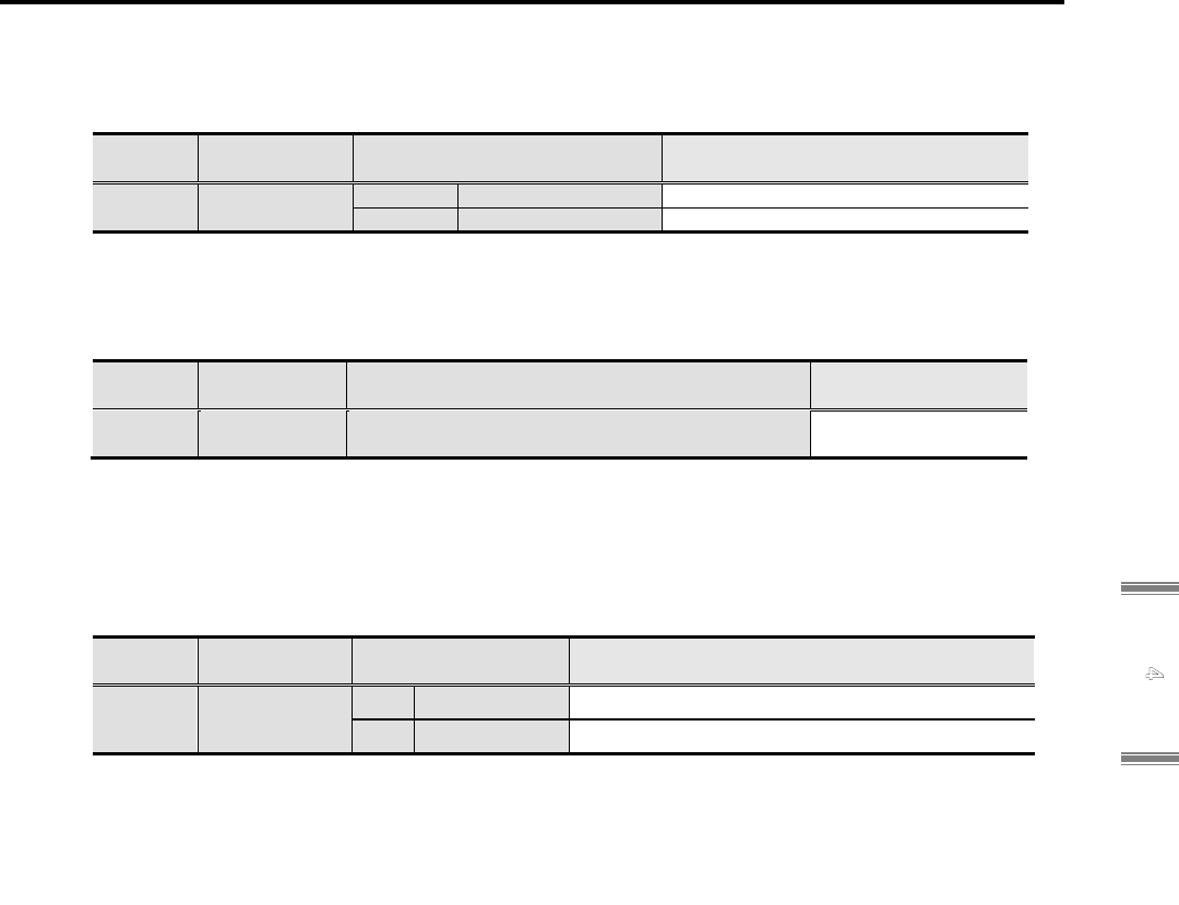
4.4 Manufacturer Specific Area
4-126
4
Ob
j
ect Dictionar
y
1) Absolute encoder (Applicable amplifier model number: RS3xxxx1xxx, RS3xxxx9xxx)
■ External encoder type code
Select the external encoder type that will be connected to EN2.
Group ID
CoE
Object ID
Selection Description
System
ID 34
0x20FF, 0x04
EXENTYPE
0x0900 EnDat_ABS EnDat2.2 / 2Mbps
0x0920 EnDat_ABS EnDat2.2 / 4Mbps
■ External absolute encoder resolution (for absolute encoder)
Sets the external encoder resolution per equal to motor single-turn.
Be valid after control power cycle.
Group ID
CoE
Object ID
Setting range Unit
System
ID 33
0x20FF, 0x03
EXPENRES
2,048 to 8,388,608 P/R
■ External Absolute Encoder Polarity Selection
Selects counting polarity of external absolute encoder.
Select polarity to get matching with increase/decrease of "Present position monitor (External
encoder) [EX-APMON]" and "Present position monitor (Motor encoder) [APMON]".
Be valid after control power cycle.
Group ID
CoE
Object ID
Selection Description
Group C
ID 0B
0x20F1, 0x04
EX-SENPOL
00 Standard Inverts not an encoder operation direction.
01 Reversed Inverts an encoder operation direction.
✔ It may become out of control if a counting direction (increase/decrease) of motor encoder
and external absolute encoder are not matched.

4. Object Dictionary
4-127
2) Incremental encoder (Applicable amplifier model number: RS3xxxx2xxx, RS3xxxxAxxx)
■ External encoder type code
Select the external encoder type that will be connected to EN2.
Group ID
CoE
Object ID
Selection Description
System
ID 34
0x20FF, 0x04
EXENTYPE
0x0002 Pulse_without_CS Incremental encoder
Wire-saving incremental encoder cannot use with full-closed control.
■ External encoder resolution (for incremental encoder)
Sets pulse amount (multiply 1) of external encoder per 1 turn of motor axis.
Be valid after control power cycle.
Group ID
CoE
Object ID
Setting range Unit
System
ID 33
0x20FF, 0x03
EXPENRES
500 to 500,000 (1-multiplied) P/R
■ External Encoder Digital Filter
Sets the digital filter for external encoder.
Even if noise is given to external incremental encoder, eliminate pulses below set value, as
noise. Considering encoder resolution and maximum operation speed of servo motor, and set
a quarter of maximum speed pulse width as a rough indication.
Group ID
CoE
Object ID
Selection Description
Group C
ID 01
0x20F1, 0x03
EX-ENFIL
00 110ns
Minimum Pulse Width =110ns
(Minimum pulse Phase Difference = 37.5ns)
01 220ns Minimum Pulse Width = 220ns
02 440ns Minimum Pulse Width = 440ns
03 880ns Minimum Pulse Width = 880ns
04 75ns
Minimum Pulse Width = 75ns
(Minimum pulse Phase Difference = 37.5ns)
05 150ns Minimum Pulse Width = 150ns
06 300ns Minimum Pulse Width = 300ns
07 600ns Minimum Pulse Width = 600ns
■ External Encoder Polarity Selection
Selects signal polarity of external incremental encoder.
Select polarity to get matching with increase/decrease of "Present position monitor (External
encoder) [EX-APMON]" and "Present position monitor (Motor encoder) [APMON]".
Be valid after control power cycle.
Group ID
CoE
Object ID
Selection Description
Group C
ID 02
0x20F1,0x04
EX-ENPOL
00 Type1
EX-Z
/without inversion
EX-B
/without inversion
EX-A
/without inversion
01 Type2
EX-Z
/without inversion
EX-B
/without inversion
EX-A
/with inversion
✔ When count direction (increase/decrease) of external incremental encoder and motor
encoder are not match, it might get runaway.

4.4 Manufacturer Specific Area
4-128
4
Ob
j
ect Dictionar
y
0x2100: Status Word 1
Index 0x2100 Indicates servo amplifier status.
Object Code
VARIABLE
Sub-Idx
Description Data Type Access PDO Initial value
0x00 Status Word 1
Indicates various internal statuses of the amplifier.
Unsigned16 RO Possible
-
MSB LSB
Zv sact eact bcnt eclrm ecsm near inps
7 6 5 4 3 2 1 0
bit0: In-Position Monitor [INPS]
Sets to "1" when the actual position is within the position
window (0x6067). (It is indefinite except for csp and ip.)
bit1: Near Range Monitor [NEAR]
Sets to "1" when the actual position is within the near range
(0x201F). (It is indefinite except for csp and ip.)
bit2: Encoder Z phase monitor [ECSM]
Sets to “1” when the C signal (Z) of the incremental encoder is
input. (It is indefinite except for INC-E.)
bit3: Encoder Clear Monitor [ECLRM]
Sets to "1" during encoder clearance.
bit4: Brake Control [BCNT]
This is a holding brake release timing output.
Sets to "1" while the brake is released.
bit5 : Actual position effective monitor [EACT]
Sets to "1" when encoder signal is readable.
bit6: Command reception-enable monitor [SACT]
Sets to"1" when command reception enabled.
bit7: Speed Zero Monitor [ZV]
Sets to "1" when the actual velocity is within zero velocity range
(0x2020) for 1ms or more.
MSB LSB
Pse psr Gests Ta vcmp Va ltg
15 14 13-12 11 10 9 8
bit8: Low Speed Monitor [LTG]
Sets to "1" when the actual velocity is in the low velocity range or
less (0x2021).
bit9: Speed Attainment Monitor [VA]
Sets to "1" when the actual velocity is in the speed attainment range
or greater (0x2002).
bit10: Speed Matching Monitor [VCMP]
Sets to "1" when the actual velocity is within the range set by
0x20F0.4.
(0x606D) selected: compare with the rotation number setting, min
-1
.
(0x202A) selected: compare with the proportion setting (%).
bit11: Torque (force) attainment monitor [TA]
Sets to “1” when internal velocity command is over Torque (force)
attainment (0x202E).
bit13,12: PP trajectory generation status monitor [GESTS]
In the Profile Position mode, indicates status of trajectory generator.
Bit13,12 = 0,0 : Stop
Bit13,12 = 0,1 : In acceleration
Bit13,12 = 1,0 : In constant velocity
Bit13,12 = 1,1 : In deceleration
bit15-14: Position sync compensation status monitor [PSE,PSR]
Monitors the status of position sync compensation.
Bit14 = "1" : In position sync compensation
Bit15 = "1" : In position deviation data receiving

4. Object Dictionary
4-129
0x2101: Amplifier Alarm Field
Index
0x2101
Indicates the alarm occurring in the servo amplifier. Sub-Index 0x00 indicates the number of
alarms that are currently occurring, and Sub-Index 0x01-0x04 indicates up to four of the
contents of alarms. Resets the alarm by setting the alarm reset in Control Word (0x6040.7).
Object Code
Array
Sub-Idx Name Description Data Type Access PDO
Initial value
0x00
Number of entry
Alarm message count in occurring Unsigned8 RO No 0x04
0x01 Error 1 : Alarm 1 [ALMACT1] Unsigned8 RO Possible 0x00
0x02 Error 2 : Alarm 2 [ALMACT2] Unsigned8 RO Possible 0x00
0x03 Error 3 : Alarm 3 [ALMACT3] Unsigned8 RO Possible 0x00
0x04 Error 4 : Alarm 4 [ALMACT4] Unsigned8 RO Possible 0x00
MSB LSB
ALMCODE
7 - 0
bit7-0: Alarm Code defined with this servo amplifier
See the Alarm Code list.
0x2102: Alarm History
Index 0x2102
Indicates the Alarm history of the servo amplifier occurring
now or previously.
Object Code Array
Sub-Idx Description Data Type Access PDO
Factory
setting
0x00 Number of entry Alarm message count Unsigned8 RO No 0x10
0x01
Present alarm [NOWALM]
✔ When the Alarm doesn’t occur, current alarm status is
shown at bit 15 to 8.
Unsigned32 RO Possible 0x00000000
0x02
1
st
past alarm [LASTAL1] Unsigned32 RO No 0x00000000
0x03
2
nd
past alarm [LASTAL2] Unsigned32 RO No 0x00000000
0x04
3
rd
past alarm [LASTAL3] Unsigned32 RO No 0x00000000
0x05
4
th
past alarm [LASTAL4] Unsigned32 RO No 0x00000000
0x06
5
th
past alarm [LASTAL5] Unsigned32 RO No 0x00000000
0x07
6
th
past alarm [LASTAL6] Unsigned32 RO No 0x00000000
0x08
7
th
past alarm [LASTAL7] Unsigned32 RO No 0x00000000
0x09
8
th
past alarm [LASTAL8] Unsigned32 RO No 0x00000000
0x0A
9
th
past alarm [LASTAL9] Unsigned32 RO No 0x00000000
0x0B
10
th
past alarm [LASTAL10] Unsigned32 RO No 0x00000000
0x0C
11
th
past alarm [LASTAL11] Unsigned32 RO No 0x00000000
0x0D
12
th
past alarm [LASTAL12] Unsigned32 RO No 0x00000000
0x0E
13
th
past alarm [LASTAL13] Unsigned32 RO No 0x00000000
0x0F
14
th
past alarm [LASTAL14] Unsigned32 RO No 0x00000000
0x10
15
th
past alarm [LASTAL15] Unsigned32 RO No 0x00000000
MSB LSB
ALMRUNTIME ALMSTS ALMCODE
31 - 16 15 - 8 7 - 0
bit7-0: Ararm Code defined by this servo amplifier
See the Ararm Code list.
bit15-8: Status when an alarm occurs
See the Status list.
bit32-16 : Cumulative operating times when an alarm
occurs (Factory setting: 0H)
The cumulative operation times when an alarm occurs (2
Hour / LSB units)
Increments every two hours after control power on.
✔ Please use as a guide of the 2 hour increments.
Bit15-8 Status (ALMSTS) list
Status display ALMSTS0
Power OFF state (P-OFF) 0x01
Power ON state (P-ON) 0x02
Servo Ready state (S-RDY) 0x03
Servo ON state (S-ON) 0x04
Servo OFF Stopping (S-OFF) 0x05
Emergency Stop state (EMR) 0x06
Initialization state 0x0F
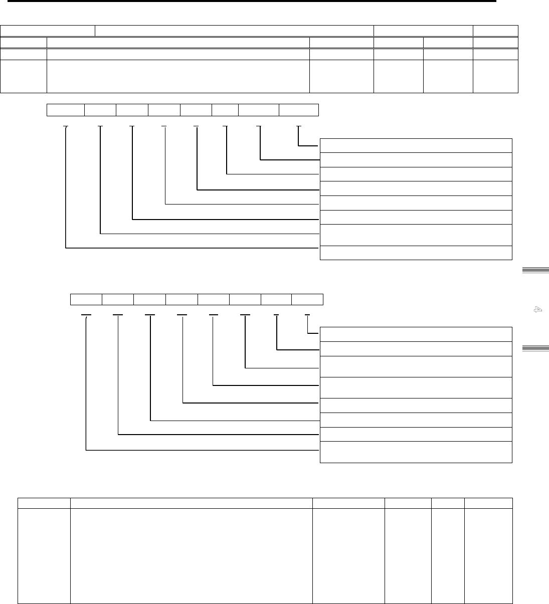
4.4 Manufacturer Specific Area
4-130
4
Ob
j
ect Dictionar
y
0x2103: Warning Status
Index 0x2103 Indicates the warnings and limitation status of the servo amplifier.
Object Code
ARRAY
Sub-Idx
Description Data Type Access PDO Initial value
0x00 Number of entry Unsigned8 RO No 0x04
0x01
Warning monitor [WARMON]
0: no warning (without limitation)
1: during warning (under limitation)
Unsigned16 RO Possible 0x0000
MSB LSB
tlw
-
vlw tlw rolw olw modw tpw
7 6 5 4 3 2 1 0
bit0: Temperature Warning
bit1: Modulo Initialization Warning
bit2: Overload Warning
bit3: Regenerative Overload Warning
bit4: While Torque Limitation
bit5: While Velocity Command Limitation
bit6: Axes Sync Excessive Error Warning
(for compatibility)
bit7: Position Deviation Warning
MSB LSB
cpew btw maxw minw hlw llw ctw pow
15 14 13 12 11 10 9 8
bit8: While Main Circuit Power Charging
bit9: Pitch Correction Table Setting Warning
bit10: While Forward Rotation (positive
direction) Overtravel
bit11: While Reverse Rotation (negative
direction) Overtravel
bit12: While Minimum Position Limiting
bit13: While Maximum Position Limiting
bit14: Encoder Warning
bit15: Control Power Voltage Reduction
Warning
Sub-Idx Description Data Type Access PDO Initial value
0x02
Warning Valid [WARENA]
Sets the valid bits of warning monitor (Sub0x01).
Sets
the warning cause which displayed to warning monitor.
(set "1")
Bits other than valid bit are fixed to zero.
Bit 7 of the status word (0x6041) will be set when a
result of AND operation of Warning Monitor and
Warning Valid is not zero.
Unsigned16 RW No 0x4E8D
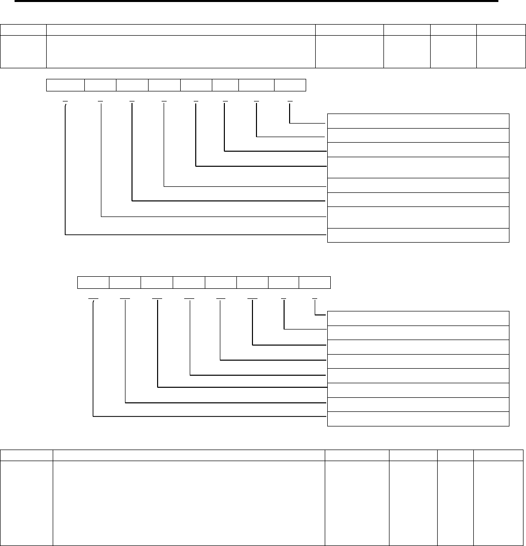
4. Object Dictionary
4-131
Sub-Idx
Description Data Type Access PDO Initial value
0x03
Warning Monitor 2 [WARMON2]
0: no warning (without limitation)
1: during warning (under limitation)
Unsigned16 RO Possible 0x0000
MSB LSB
- - - - - - - -
7 6 5 4 3 2 1 0
bit0: Axes Sync Excessive Error Warning
bit1: Dual Position Error Excess Warning
bit2: Reserved
bit3: Adaptive Notch Filter E Frequency
Warning
bit4: Reserved
bit5: External Encoder Warning
bit6: Position Deviation Difference Excess
Warning
bit7: Reserved
MSB LSB
- - - - - - - -
15 14 13 12 11 10 9 8
bit8: Reserved
bit9: Reserved
bit10: Reserved
bit11: Reserved
bit12: Reserved
bit13: Reserved
bit14: Reserved
bit15: Reserved
Sub-Idx
Description Data Type Access PDO Initial value
0x04
Warning Valid 2 [WARENA2]
Sets the valid bits of warning monitor 2 (Sub0x03).
Sets the
warning cause which displayed to warning monitor. (set "1")
Bits other than valid bit are fixed to zero.
Bit 7 of the status word (0x6041) will be set when a result of
AND operation of Warning Monitor and Warning Valid is not
zero.
Unsigned16 RW No 0x0000

4.4 Manufacturer Specific Area
4-132
4
Ob
j
ect Dictionar
y
0x2104: Actual Gain Value Monitor
Index 0x2104
Indicates the actual setting value of the gain parameter to switch to real time
various gain parameters through auto-tuning or gain switching selection.
Object Code Array
Sub-Idx
Description Data Type
Acce
ss
PDO Initial value
0x00 Number of entry Unsigned8 RO No 0x08
0x01
Position Loop Proportional Gain Actual Monitor [KPMON]
Outputs the value of the position loop gain (0x2005) that is switched in
auto-tuning mode (0x2002) or the gain switching selection (0x2001, bit
5-4), and is currently used for the servo control.
Unsigned16 RO Possible 0x001E
(30)
Display range
0x0001-0x0BB8 (1 to 3000)
Unit
1 /s
0x02
Position Loop Integral Time Constant Actual Monitor
[TPIMON]
Outputs the value of the position integral time constant (0x2006) that is
switched in auto-tuning mode (0x2002) or the gain switching selection
(0x2001, bit 5-4), and is currently used for the servo control.
Unsigned16 RO Possible 0x2710
(1000)
Proportional
control
Display range 0x0003-0x2710 (0.3 to 1000)
Unit
0.1 ms
0x03
Velocity Loop Proportional Gain Actual Monitor [KVPMON]
Outputs the value of the velocity loop proportional gain (0x200B) that is
switched in auto-tuning mode (0x2002) or the gain switching selection
(0x2001, bit 5-4), and is currently used for the servo control.
Unsigned16 RO Possible 0x0032
(50)
Display range 0x0001-0x07D0 (1 to 2000)
Unit Hz
0x04
Velocity Loop Integral Time Constant Monitor [TVIMON]
Outputs the value of the velocity loop integral time constant (0x200C) that
is switched in auto-tuning mode (0x2002) or the gain switching selection
(0x2001, bit 5-4), and is currently used for the servo control.
Unsigned16 RO Possible 0x00C8
(20)
Display range 0x0003-0x2710 (0.3 to 1000)
Unit
0.1 ms
0x05
Load Inertia Moment Ratio Actual Monitor [JRATMON]
Outputs the value of the load inertia moment ratio (0x200D) that is
switched in auto-tuning mode (0x2002) or the gain switching selection
(0x2001, bit 5-4), and is currently used for the servo control.
Unsigned16 RO Possible 0x0064
(100)
Display range 0x0000-0x3A98 (0 to 15000)
Unit %
0x06
Torque (force) Command Filter Actual Monitor [TCFILMON]
Outputs the value of the torque command filter (0x2011) that is switched
in auto-tuning mode (0x2002) or the gain switching selection (0x2001, bit
5-4), and is currently used for the servo control.
Unsigned16 RO Possible 0x0258
(600)
Display range
0x0001~0x07D0(1 to 2000)
Unit Hz
0x07
Model Control Gain Actual Monitor [MKPMON]
Outputs the value of the model control gain (0x2017) that is switched in
auto-tuning mode (0x2002) or the gain switching selection (0x2001, bit
5-4), and is currently used for the servo control.
Unsigned16 RO Possible 0x001E
(30)
Display range 0x0001-0x0BB8 (1 to 3000)
Unit
1 /s
0x08
Adaptive Notch Filter Monitor [ADNFEMON]
Indicates the adaptive notch filter frequency.
Outputs the value currently used for the servo control.
Unsigned16 RO Possible 0x0064
(100)
Display range 0x0064-0x03E8,0x0FA0
(100 to 1000,4000)
Unit Hz

4. Object Dictionary
4-133
0x2105: Zero-phase Based Actual Position
Index 0x2105 Indicates the Actual Position from Zero-phase. Object Code
VARIABLE
Sub-Idx Description Data Type Access PDO Initial value
0x00
Zero-phase Based Actual Position [CCUNIT]
◆In the incremental encoder,
indicates the position within one rotation based on Z phase.
The location increases to the direction of CCW seen head-on.
Integer32 RO Possible
-
Display range 0x00000000-0xFFFFFFFF
(0 to 4294967295)
Unit Pulse
The unit is 1 Pulse/LSB, and four-fold value of A・B phases.
✔ It is indefinite after power ON until Z phase is detected. (Example: At the 1024P/Re encoder, 0 – 4095 pulse indicated)
◆In the Absolute Encoder,
indicates the position within one rotation based on Absolute Positon.
0x2106: Internal Velocity Command Monitor
Index 0x2106
Has the actual velocity value calculated from the position encoder.
The value is provided by the user-defined velocity unit.
Object Code
VARIABLE
Sub-Idx Description Data Type Access PDO Initial value
0x00
Internal Velocity Demand Value Monitor [VCMON]
An Internal Velocity Command Value after passing the Velocity
Command low-pass filter.
Integer32 RO Possible
-
Display range 0x80000000-0x7FFFFFFF
(-2147483648 to 2147483647)
Unit Pulse/s
0x2107: Internal Torque (force) Command Monitor
Index 0x2107
Indicates the torque (force) command monitor inside the servo
amplifier.
Object Code
VARIABLE
Sub-Idx
Description Data Type Access PDO Initial value
0x00
Internal Torque (force) Demand Value Monitor [TCMON]
An Internal Torque (force) Command value after passing the
Velocity Command low-pass filter. It is indicated at the ratio
with the motor rated torque (force) 100%.
Integer16 RO Possible
-
Display range 0x8000-0x7FFF
(-3276.8 to 3276.7)
Unit 0.1 %

4.4 Manufacturer Specific Area
4-134
4
Ob
j
ect Dictionar
y
0x2108: Motor utilization monitor (Effective torque (force) estimate value)
Index 0x2108
Indicates the estimation value of the Effective Motor Torque (force).
Object Code
VARIABLE
Sub-Idx Description Data Type Access PDO Initial value
0x00 Number of entry Unsigned8 RO No 0x02
0x01
Effective Torque (force) Estimated Value [TRMS]
Indicates the effective torque (force) estimated value against
the motor rated torque (force).
✔ The exact value is indicated, but in some operation patterns, it
may take several hours to stabilize the value.
Unsigned16 RO Possible
-
Display range 0x0000-0xFFFF
(0 to 6553.5)
Unit 0.1%
0x02 Effective Torque (force) Fast Estimated Value
[ETRMS]
Indicates the Effective Motor Torque (force) of time constant
(1/16) against TRMS.
✔ Quick estimation is possible in applications where short-cycle
operation patterns are repeated.
Unsigned16 RO Possible
-
Display range 0x0000-0xFFFF
(0 to 6553.5)
Unit 0.1%
0x2109: Servo Amplifier Internal Temperature
Index 0x2109 Indicates the temperature inside the servo amplifier. Object Code
VARIABLE
Sub-Idx Description Data Type Access PDO Initial value
0x00
Internal Temperature Monitor [ATEMP]
The temperature monitor value inside the servo amplifier (near
the power module). The unit is the Celsius degree and
indicated by 1 °C / LSB.
Integer16 RO Possible
-
Display range 0x8000-0x7FFF
(-32768 to 32767)
Unit °C
Conversion to Fahrenheit (F) is calculated according to the following formula: F = 9 / 5 * C+32.
0x210A: Regenerative Resistor Operation Percentage Monitor
Index 0x210A
An estimate monitor of the operating ratio of the servo amplifier
regenerative resistor.
Object Code
VARIABLE
Sub-Idx Description Data Type Access PDO Initial value
0x00 Regenerative Resistor Operation Percentage Monitor
[REGP]
Operating percentage monitor of regenerative resistor
representing the regenerator-ON time ratio per 1 second.
Unsigned16 RO Possible 0x0000
(0)
Display range 0x0000-0xFFFF (0 to 655.35)
Unit 0.01 %
The regenerative electricity PM is calculated according to the following formula, using this monitor value.
PM (W) = 400
2
(V)/regenerative resistor (ohm)×Regenerative resistor operating percentage (%)/100(%)
0x210B: Encoder Temperature Monitor
Index 0x210B The temperature of an encoder is displayed. Object Code Array
Sub-Idx Description Data Type Access PDO Initial value
0x00 Number of entry Unsigned8 RO No 0x02
0x01
Encoder Temperature Monitor [ETEMP]
The monitor value of the temperature of the encoder control
board, shown in the unit of °C Celsius/LSB.
Integer16 RO Possible
-
Display range 0xFF80-0x007F (-128 to 127)
Unit °C
✔
The encoder temperature is detected at the time that the servo amplifier stops. If the stop status continues, the encoder temperature
monitor continuously and repeatedly detects the temperature of the encoder each 1s cycle.
✔
When the encoder temperature detection is set to disable (0x2000 bit13 = 1), it will not detect the temperature.
0x02
External Encoder Temperature Monitor [EXETEMP]
The monitor value of the temperature of the encoder control
board, shown in the unit of °C Celsius/LSB.
Integer16 RO Possible
-
Display range 0xFF80-0x007F (-128 to 127)
Unit °C
0x210C: Home Index Position
Index 0x210C
Home Index Positions latched by various methods of homing
modes.
Object Code
VARIABLE
Sub-Idx Description Data Type Access PDO Initial value
0x00
Home Index Position [HOMEIDX]
When homing activate and lached home index then
indicates Internal position.
Indicates, the counter value based on control power ON with
incremental system, or the absolute value of encoder data
with absolute system.
Integer32 RO Possible
-
Display range 0x80000000-0x7FFFFFFF
(-2147483648 to 2147483647)
Unit Pulse
0x210D: Position Synchronization Deviation Monitor
Index 0x210D
Position deviation between two synchronous connected
amplifiers is monitored.
Object Code
VARIABLE
Sub-Idx Description Data Type Access PDO Initial value
0x00 Position Synchronization Deviation Monitor
[PSYNDEV]
When position synchronization correction function is valid, the
monitor indicates error pulse quantity from position deviation
of amplifiers which are subject to synchronization.
Integer32 RO Possible
-
Display range 0x80000000-0x7FFFFFFF
(-2147483648 to 2147483647)
Unit Pulse

4. Object Dictionary
4-135
0x2110: Control Cycle Actual Position
Index 0x2110
Returns the Actual Position value latched every control cycle (125μs).
Unit of Monitor is expressed by the resolution of the motor encoder used.
Object Code Array
Sub-Idx Description Data Type Access PDO Initial value
0x00 Number of entry Unsigned8 RO No 0x07
0x01 Control Cycle Actual Position 1
Actual position at 125μs previous of 0x6064.
Integer32 RO Possible -
0x02 Control Cycle Actual Position 2
Actual position at 250μs previous of 0x6064.
Integer32 RO Possible -
0x03 Control Cycle Actual Position 3
Actual position at 375μs previous of 0x6064.
Integer32 RO Possible -
0x04 Control Cycle Actual Position 4
Actual position at 500μs previous of 0x6064.
Integer32 RO Possible -
0x05 Control Cycle Actual Position 5
Actual position at 625μs previous of 0x6064.
Integer32 RO Possible -
0x06 Control Cycle Actual Position 6
Actual position at 750μs previous of 0x6064.
Integer32 RO Possible -
0x07 Control Cycle Actual Position 7
Actual position at 875μs previous of 0x6064.
Integer32 RO Possible -
✔ Control cycle will be 250μs when scale function is used.
✔ It cannot use when high speed sampling mode is used.
Display range 0x80000000-0x7FFFFFFF
(-2147483648 to 2147483647)
Unit UP (User Position unit)
0x2111: Control Cycle Actual Velocity
Index 0x2111
Returns the Actual Velocity value latched every control
cycle (125μs).
Object Code Array
Sub-Idx Description Data Type Access PDO Initial value
0x00 Number of entry Unsigned8 RO No 0x07
0x01 Control Cycle Actual Velocity 1
Actual velocity at 125μs previous of 0x606C.
Integer32 RO Possible -
0x02 Control Cycle Actual Velocit
y
2
Actual velocity at 250μs previous of 0x606C.
Integer32 RO Possible -
0x03 Control Cycle Actual Velocity 3
Actual velocity at 375μs previous of 0x606C.
Integer32 RO Possible -
0x04 Control Cycle Actual Velocity 4
Actual velocity at 500μs previous of 0x606C.
Integer32 RO Possible -
0x05 Control Cycle Actual Velocity 5
Actual velocity at 625μs previous of 0x606C.
Integer32 RO Possible -
0x06 Control Cycle Actual Velocity 6
Actual velocity at 750μs previous of 0x606C.
Integer32 RO Possible -
0x07 Control Cycle Actual Velocity 7
Actual velocity at 875μs previous of 0x606C.
Integer32 RO Possible -
✔ Data is filtered and the cutoff frequency is 250Hz.
✔ Control cycle will be 250μs when scale function is used.
✔ It cannot use when high speed sampling mode is used.
Display range 0x80000000-0x7FFFFFFF
(-2147483648 to 2147483647)
Unit UP (User Position unit) /s
0x2112: Control Cycle Actual Torque (force)
Index 0x2112
Returns the Actual Torque (force) value latched every
control cycle (125μs).
Object Code Array
Sub-Idx Description Data Type Access PDO Initial value
0x00 Number of entry Unsigned8 RO No 0x07
0x01 Control Cycle Actual Torque (force) 1
Actual torque (force) at 125μs previous of 0x6077.
Integer16 RO Possible -
0x02 Control Cycle Actual Torque (force) 2
Actual torque (force) at 250μs previous of 0x6077.
Integer16 RO Possible -
0x03 Control Cycle Actual Torque (force) 3
Actual torque (force) at 375μs previous of 0x6077.
Integer16 RO Possible -
0x04 Control Cycle Actual Torque (force) 4
Actual torque (force) at 500μs previous of 0x6077.
Integer16 RO Possible -
0x05 Control Cycle Actual Torque (force) 5
Actual torque (force) at 625μs previous of 0x6077.
Integer16 RO Possible -
0x06 Control Cycle Actual Torque (force) 6
Actual torque (force) at 750μs previous of 0x6077.
Integer16 RO Possible -
0x07 Control Cycle Actual Torque (force) 7
Actual torque (force) at 875μs previous of 0x6077.
Integer16 RO Possible -
✔ Unit of monitor is defined by the set value of 0x2078, Torque
Scale Selection.
✔ Control cycle will be 250μs when scale function is used.
✔ It cannot use when high speed sampling mode is used.
Display range 0x8000-0x7FFF (-32768 to 32767)
Unit
UT (User Torque unit)

4.4 Manufacturer Specific Area
4-136
4
Ob
j
ect Dictionar
y
0x2116: Actual Velocity 2
Index 0x2116
Has the actual velocity value calculated from the position
encoder. The value is provided by the user-defined velocity
unit.
Object Code
VARIABLE
Sub-Idx
Description Data Type Access PDO Initial value
0x00
Actual Velocity [ACVMON2]
✔ Data is filtered and the cutoff frequency is 20Hz.
Integer32 RO Possible
-
Display range
0x80000000-0x7FFFFFFF
(-2147483648 to 2147483647)
Unit
UP (User Position unit) /s
0x2117: Actual Position 2
Index 0x2117
Indicates the actual position without backlash correction
value.
Object Code
VARIABLE
Sub-Idx
Description Data Type Access PDO Initial value
0x00
Actual Position 2 [APMON2]
Indicates the actual position without backlash
correction value.
Integer32 RO Possible
-
Display
range
0x80000000-0x7FFFFFFF
(-2147483648 to 2147483647)
Unit
UP (User Position unit)
◆With backlash correction
Actual Position 2 = Actual Position (0x6064) - Backlash correction value (0x5091)
◆Without backlash correction
Actual Position 2 = Actual Position
0x2118: Encoder Monitor
Index 0x2118 Indicates the position in encoder.
Object Code
VARIABLE
Sub-Idx
Description Data Type Access PDO Initial value
0x00 Number of entry Unsigned8 RO No 0x02
0x01
Motor Encoder Monitor [EPMON]
Indicates the position in motor encoder.
This is the value before homing.
Indication differs depending on encoder type.
Integer32 RO Possible
-
Display range
0x80000000-0x7FFFFFFF
(-2147483648 to 2147483647)
Unit
Pulse
✔ Combination encoder: incremental encoder
It becomes zero at control power on, and shows the value of 32bit-up/down free run counter that is
multiplied 4 to A and B signals.
✔ Combination encoder: absolute encoder
It shows the current position of encoder that includes multi turn data.
For the single turn absolute encoder, it shows the current position of encoder within single turn.
0x02
External Encoder Monitor [EX_EPMON]
Indicates the position in external encoder.
This is the value before homing.
Integer32 RO Possible
-
Display range
0x80000000-0x7FFFFFFF
(-2147483648 to 2147483647)
Unit
Pulse
It becomes zero at control power on, and shows the value of 32bit-up/down free run counter that is
multiplied 4 to A and B signals.
✔ This monitor is valid when 0x01 is set to 0x20F3.2 "Position Loop Control Encoder Selection".
In use of Hall effect sensor with linear motor, it shows the data of Hall effect sensor.
0x211F: Digital Input Monitor 2
Index 0x211F Indicates lower 16bit of the Digital inputs (0x60FD).
Object Code
VARIABLE
Sub-Idx
Description Data Type Access PDO Initial value
0x00
Digital Input Monitor [DINPUT16]
Monitors input status.
Unsigned16 RO Possible
-
Display range
0x0000-0xFFFF
Indicates the same content as lower 16bit of the Digital inputs (0x60FD).
It shows state of EMR, Homem, PositiveLimit and NegativeLimit.

4. Object Dictionary
4-137
0x2121: Production Number
Index 0x2121 Indicates the production number of product.
Object Code
VARIABLE
Sub-Idx Name/Description Data Type Access PDO Value
0x00 Production Number [Production number]
Production number of servo amplifier at factory
shipment is indicated.
Visible String
(Unsigned32)
RO No Character
strings
(-)
Production number is 10 digits.
12 15 02 1234
Month Year Date Production number
0x2123: Cooling Fan Rotation Speed
Index 0x2123 Indicates the rotation speed of cooling fan.
Object Code
VARIABLE
Sub-Idx
Description Data Type Access PDO Initial value
0x00 Cooling Fan Rotation Speed [FANVEL]
Indicates the rotation speed of cooling fan.
Unsigned16 RO Possible 0x0000
(0)
Display range
0x0000-0xFFFF
(0 to 65535)
Unit
min
-1
0x2124: U-phase Electric Angle Monitor
Index 0x2124 Indicates the U-phase electric angle.
Object Code
VARIABLE
Sub-Idx
Description Data Type Access PDO Initial value
0x00 U-phase Electric Angle Monitor [CSU]
Indicates the U-phase electric angle.
Always indicated except in case of encoder error.
Unsigned16 RO Possibl
e
0x0000
(0)
Display range
0x0000-0x0167
(0 to 359)
Unit
degree
0x2125: Average Power Monitor
Index 0x2125 Indicates the average power.
Object Code
VARIABLE
Sub-Idx
Description Data Type Access PDO Initial value
0x00 Average Power Monitor [MAVEPOW1]
For average power, it is indicated by measure result
every 1 minute.
Integer32 RO Possible 0x00000000
(0.0)
Display range
0xFF676981-0x0098967F
(-999999.9 to 999999.9)
Unit
0.1 W
✔ Not shown with the motor except R series.
✔ When 3-phase 200V AC is used to the 200V AC input type, accuracy will be ±25% (at the accel/decel
operation with 100% effective torque).
✔ When single-phase 200V AC is used to the 200V AC input type, accuracy will be ±30% (at the accel/decel
operation with 100% effective torque).
✔ For the 100V AC input type, accuracy will be ±30% (at the accel/decel operation with 100% effective torque).
(Accuracy may be worse when it is used at the instantaneous area of Velocity-torque characteristics.)
0x2126: Average Power Monitor
Index 0x2126 Indicates the average power.
Object Code
VARIABLE
Sub-Idx
Description Data Type Access PDO Initial value
0x00 Average Power Monitor [MAVEPOW2]
For average power, it is indicated by measure result
every 1 minute.
✔ Not shown with the motor except R series.
Integer16 RO Possible 0x0000
(0.0)
Display range
0xD8F1-0x270F
(-999.9 to 999.9)
Unit
0.1 kW
✔ When 3-phase 200V AC is used to the 200V AC input type, accuracy will be ±25% (at the accel/decel
operation with 100% effective torque).
✔ When single-phase 200V AC is used to the 200V AC input type, accuracy will be ±30% (at the accel/decel
operation with 100% effective torque).
✔ For the 100V AC input type, accuracy will be ±30% (at the accel/decel operation with 100% effective torque).
(Accuracy may be worse when it is used at the instantaneous area of Velocity-torque characteristics.)

4.4 Manufacturer Specific Area
4-138
4
Ob
j
ect Dictionar
y
0x2127: Each Control Status
Index 0x2127
Indicates the each control status.
Dedicated for manufacturer management only.
Object Code
ARRAY
Sub-Idx
Description Data Type Access PDO Initial value
0x00 Number of entry Unsigned8 RO No 0x07
0x01
Control Status [CSTATE]
Unsigned16 RO No 0x0000
Display range
0x0000-0xFFFF
0x02
Position Control Status [PSTATE]
Unsigned16 RO No 0x0000
Display range
0x0000-0xFFFF
0x03
Velocity Control Status [VSTATE]
Unsigned16 RO No 0x0000
Display range
0x0000-0xFFFF
0x04
Torque Control Status [TSTATE]
Unsigned16 RO No 0x0000
Display range
0x0000-0xFFFF
0x05
Amplifier Management Signal Status [PCM_STA]
Unsigned8 RO No 0x00
Display range
0x00-0xFF
0x06
Alarm Management Status [PCM_ALM]
Unsigned16 RO No 0x0000
Display range
0x0000-0xFFFF
0x07
Function Management Signal Status [PCM_FUNC]
Unsigned16 RO No 0x0000
Display range
0x0000-0xFFFF
0x2128: U-phase Current Readout Value
Index 0x2128 Indicates th U-phase Current Readout Value.
Object Code
VARIABLE
Sub-Idx
Description Data Type Access PDO Initial value
0x00
U-phase Current Readout Value [IFEDU0]
Indicates th U-phase Current Readout Value.
Integer16 RO No 0x0000
Display range
0x8000-0x7FFF
0x2129: V-phase Current Readout Value
Index 0x2129 Indicates th V-phase Current Readout Value.
Object Code
VARIABLE
Sub-Idx
Description Data Type Access PDO Initial value
0x00
V
-phase Current Readout Value [IFEDV0]
Indicates th V-phase Current Readout Value.
Integer16 RO No 0x0000
Display range
0x8000-0x7FFF
0x212A: Motor Encoder Communication Error Counter
Index 0x212A Indicates count of motor encoder communication error.
Object Code
VARIABLE
Sub-Idx
Description Data Type Access PDO Initial value
0x00 Motor Encoder Communication Error Counter
[ERRCNTM]
Indicates count of motor encoder communication
error.
Unsigned32 RO No 0x0000
Display range
0x00000000-0xFFFFFFFF
0x212B: External Encoder Communication Error Counter
Index 0x212B Indicates count of external encoder communication error.
Object Code
VARIABLE
Sub-Idx
Description Data Type Access PDO Initial value
0x00 External Encoder Communication Error Counter
[ERRCNTE]
Indicates count of external encoder communication
error.
Unsigned32 RO No 0x000000
00
Display range
0x00000000-0xFFFFFFFF
0x212C: Motor Encoder Frequency Monitor
Index 0x212C Indicates the encoder frequency.
Object Code
Array
Sub-Idx
Description Data Type Access PDO Initial value
0x00 Number of entry Unsigned8 RO No 0x02
0x01 Motor Encoder Frequency Monitor
[MMOENCF]
Indicates the motor encoder frequency in
incremental encoder use.
Integer32 RO Possible
-
Display range
0x80000000-0x7FFFFFFF
(-2147483648 to 2147483647)
Unit
kPulse/s
0x02 External Encoder Frequency Monitor
[MEXENCF]
Indicates the external encoder frequency in
incremental encoder use.
Integer32 RO Possible
-
Display range
0x80000000-0x7FFFFFFF
(-2147483648 to 2147483647)
Unit
kPulse/s

4. Object Dictionary
4-139
0x212D: Internal position Offset with Homing
Index 0x212D Indicates an internal position offset with homing.
Object Code
VARIABLE
Sub-Idx
Description Data Type Access PDO Initial value
0x00
Internal position Offset with Homing [HOMEOFS]
Indicates an internal position offset with homing.
Integer64 RO No
-
Display range
0x8000000000000000
-0x7FFFFFFFFFFFFFFF
Unit
Pulse
0x212E: Amplifier Operation Time
Index 0x212E Indicates accumulate of control power ON time.
Object Code
VARIABLE
Sub-Idx
Description Data Type Access PDO Initial value
0x00
Amplifier Operation Time [RUNTIM]
Indicates accumulate of control power ON time.
Integer64 RO No
-
Display range
0x8000000000000000
-0x7FFFFFFFFFFFFFFF
Display
format
ms
0x212F: Overload Detection Temperature Attainment Ratio
Index 0x212F
Indicates the Overload Detection Temperature
Attainment Ratio.
Object Code
VARIABLE
Sub-Idx
Description Data Type Access PDO Initial value
0x00 Overload Detection Temperature Attainment
Ratio [OLRAT]
Indicates ratio against overload detection
temperature.
Unsigned16 RO No
-
Display range
0x0000-0x03E8
(0.0 to 100.0%)
Unit %
0x2131: Position Deviation Difference Monitor
Index 0x2131 Indicates the Position Deviation Difference. Object Code VARIABLE
Sub-Idx Description Data Type Access PDO Initial value
0x00 Position Deviation Difference Monitor
[PDEVID]
Indicates the Position Deviation Difference.
(Refer the section 5.16.1, for detail.)
Integer32 RO Possible
-
Display range 0x80000000 to 0x7FFFFFFF
(-2147483648 to 2147483647 Pulse)
Unit Pulse
0x2134: Life-span monitor
Index 0x2134 Indicates each kind of remaining life. Object Code Array
Sub-Idx Description Data Type Access PDO Initial value
0x00 Number of entry Unsigned8 RO No 0x04
0x01 Remaining life of relay for an inrush current
prevention [RSRLYLF]
Accumulates ON/OFF count of a relay for an inrush
current prevention, and estimates a remaining life
from available switching count on specifications.
Unsigned16 RO Possible
-
Display range 0x0000 to 0x2710
(0.00 to 100.00)
Unit 0.01%
0x02 Remaining life of relay for a dynamic brake
[DBRLYLF]
Accumulates ON/OFF count of a relay for a
dynamic brake, and estimates a remaining life
from available switching count on specifications.
Unsigned16 RO Possible
-
Display range 0x0000 to 0x2710
(0.00 to 100.00)
Unit 0.01%
0x03 Remaining life of relay for a holding brake
[HBRLYLF]
Accumulates ON/OFF count of a relay for a holding
brake, and estimates a remaining life from
available switching count on specifications.
Measures just 400V input type.
For the other type amplifiers, "100.00%" is
indicated.
Unsigned16 RO Possible
-
Display range 0x0000 to 0x2710
(0.00 to 100.00)
Unit 0.01%
0x04 Remaining life of a holding brake
[HBLF]
Checks motor position change from the point of
braking (holding brake signal turns OFF) to the
point of slipping after brake, and estimates a
remaining life of holding brake.
Applies just the motor supporting remaining life of
a holding brake.
For the other motors, "100.00%" is indicated.
Unsigned16 RO Possible
-
Display range 0x0000 to 0x2710
(0.00 to 100.00)
Unit 0.01%

4.4 Manufacturer Specific Area
4-140
4
Ob
j
ect Dictionar
y
0x2135: Electric power monitor
Index 0x2135 Indicates each kind of electric power. Object Code Array
Sub-Idx Description Data Type Access PDO Initial value
0x00 Number of entry Unsigned8 RO No 0x01
0x01
Regenerative power monitor [RegPOW]
Indicates the power consumption of regenerative
resistor.
Unsigned32 RO Possible
-
Display range 0x00000000 to 0xFFFFFFFF
(0.000 to 4294967.295)
Unit 0.001W
0x2136: Communication quality monitor
Index 0x2136 Indicates each kind of communication error rate. Object Code Array
Sub-Idx Description Data Type Access PDO Initial value
0x00 Number of entry Unsigned8 RO No 0x03
0x01 Error rate of motor encoder communication
[MOTE_ERRAT]
Indicates the
error rate of motor encoder
communication.
Unsigned32 RO Possible
-
Display range 0x00000000 to 0x000F4240
(0.000000 to 1.000000)
Unit
×10
-6
0x02 Error rate of external encoder communication
[EXTE_ERRAT]
Indicates the
error rate of external encoder
communication.
Unsigned32 RO Possible
-
Display range 0x00000000 to 0x000F4240
(0.000000 to 1.000000)
Unit
×10
-6
0x03 Error rate of EtherCAT communication
[ECAT_ERRAT]
Indicates the
error rate of EtherCAT
communication.
Unsigned32 RO Possible
-
Display range 0x00000000 to 0x000F4240
(0.000000 to 1.000000)
Unit
×10
-6
✔ It shows error count ratio against communication count per second.
0x2138: Backup file information
Index 0x2138 Indicates the file information for FoE upload. Object Code Array
Sub-Idx Description Data Type Access PDO Initial value
0x00 Number of entry Unsigned8 RO No 0x01
0x01
Backup file size [FileSize]
Indicates the file size of amplifier parameter file
(ap1) generated when performing parameter
saving (0x1010), with byte unit. Indicates zero
when file is not exist. During a file generating,
stored size will be updated.
Unsigned32 RO No
-
Display range 0x00000000 to 0xFFFFFFFF
Unit Byte
Note) This object will be abolished due to integration to 0x2139. Backup file size will be replaced to 0x2139-1.
0x2139: Upload File Information
Index 0x2139 Upload File Information Object Code ARRAY
Sub-Idx Description Data type Access PDO Initial value
0x00 Number of entry Unsigned8 RO No 0x03
0x01 AP1 File Size
Indicates the file size of amplifier parameter file (ap1)
generated when performing parameter saving (0x1010),
with byte unit. Indicates zero when file is not exist. During
a file generating, stored size will be updated.
Unsigned32 RO No 0x00000000
Display range 0 to 0xFFFFFFFF
(0 to 4294967295)
Unit byte
0x02 Drive Recorder File Size
Indicates the data file size if a data of drive recorder
getting is exist. Indicates zero when data is not exist.
Unsigned32 RO No 0x00000000
Display range 0 to 0xFFFFFFFF
(0 to 4294967295)
Unit byte
0x03 System Analysis File Size
Indicates the data file size if a data of system analysis
getting is exist. Indicates zero when data is not exist.
Unsigned32 RO No 0x00000000
Display range 0 to 0xFFFFFFFF
(0 to 4294967295)
Unit byte

4. Object Dictionary
4-141
0x213A: Motor Serial Number
Index 0x213A Indicates the serial number of connected motor.
Object Code
VARIABLE
Sub-Idx
Description
Data Type
A
ccess
PDO Initial value
0x00 Motor Serial Number
Indicates the serial number of connected motor.
Visible String RO No Character
strings
(-)
Indicates "・・・・・・・・・・・・" if the motor is not applied to motor auto setting or uses incremental encoder.
0x213B: Motor Information
Index 0x213B Indicates the motor/encoder informations of connected motor. Object Code ARRAY
Sub-Idx Description Data type Access PDO Initial value
0x00 Number of entry Unsigned8 RO No 0x02
0x01 Motor Information
Indicates the connecting motor informations.
Unsigned32 RO No 0x00000000
Display range 0x00000000 to 0xFFFFFFFF
Unit -
Indicates 0xFFFFFFFF for the motor unsupporting a motor auto setting.
0x 0000 0184
0x02 Encoder Information
Indicates the connecting encoder informations.
Indicates 0xFFFFFFFF for the motor unsupporting a
motor auto setting.
Unsigned16 RO No 0x0000
Display range 0x0000 to 0xFFFF
Unit -
0x 2 0 6 6
Example) In case that Battery-less absolute encoder (HA035)/Communication baud rate 2.5 MHz/Multi-turn
data 65536/Resolution 131072, "0x2066" is shown.
Bit3-0: Rotary encodeolution [P/R]
0: 2048 1: 4096 2: 8192
3: 16384 4: 32768 5: 65536
6: 131072 7: 262144 8: 524288
9: 1048576 A: 2097152 B: 4194304
C: 8388608 D: 16777219 E: 33554432
F: Reserved
Bit7-4: Rotary encoder multi-turn data length
0: 0 1: 2048 2: 4096
3: 8192 4: 163845: 32768 5: 32768
6: 65536 7: 131072 8 to F: Reserved
Bit11-8: Communication baud rate
0: 2.5MHz 1: 4.0MHz 2 to F: Reserved
Bit15-12: Encoder function code
0: Single-turn absolute encoder (PA035S)
1: Battery backup absolute encoder (PA035C)
2: Battery-less absolute encoder (HA035)
3 to F: Reserved
Bit15-0: Motor code
Identification codes for every motor model number.
Refer Index: 0x20FE for motor code.
Bit31-16: Holding brake information
0x0000: Without brake
0x0001: With brake (90V DC)
0x0002: With brake (24V DC)
0x0003 to 0xFFFF: Reserved

4.4 Manufacturer Specific Area
4-142
4
Ob
j
ect Dictionar
y
0x5080: Correction Table Control
Index 0x5080 Enables/disables the correction table function.
Object Code
VARIABLE
Sub-Idx
Description Data Type Access PDO Initial value
0x00
Correction Table Control [COTBLEN]
Unsigned8 RW No 0x00
Enables/disables the correction table function. Setting range 0x00-0x01
0x00: Disabled
0x01: Enabled
0x02 - 0xFF: Reserved
0x5081: Correction Table Interpolation Method
Index 0x5081 Sets the interpolation method of the correction table.
Object Code
VARIABLE
Sub-Idx
Description Data Type Access PDO Initial value
0x00
Correction Table Interpolation Method [COTBLINTP]
Unsigned8 RW No 0x00
Sets the interpolation method of the correction table. Setting range 0x00
0x00: Linear
0x01-0xFF: Reserved
0x5082: Correction Table Extrapolation Method
Index 0x5082 Sets the extrapolation method of the correction table.
Object Code
VARIABLE
Sub-Idx
Description Data Type Access PDO Initial value
0x00
Correction Table Extrapolation Method [COTBLEXTP]
Unsigned8 RW No 0x00
Sets the extrapolation method of the correction table. Setting range 0x00
0x00: Linear
0x01-0xFF: Reserved

4. Object Dictionary
4-143
0x5083: Correction Table Position
Index 0x5083 Correction Table Position
Object Code
ARRAY
Sub-Idx
Description Data Type Access PDO Initial value
0x00 Number of entry
✔ It becomes valid after control power cycle.
Unsigned8 RW No 0x00
Setting range 0x00~0x40
0x01 Entry 1
Correction Position 1
Integer32 RW No 0x0000000
0
Setting range 0x80000000-0x7FFFFFFF
Unit UP (User Position unit)
0x02
to
n
Entry 2 to Entry n
Correction Position
2 to Correction Position n
Integer32 RW No 0x0000000
0
Setting range 0x80000000-0x7FFFFFFF
Unit UP (User Position unit)
✔ "n" is up to 0x40 in maximum.
✔ Set as follows: Correction position n-1< Correction position n. (n=2 to 64)
If the relation above is not given at power ON initialization, 0x2103 Warning status bit9 is changed to "1".
Adjust the correction position, and then perform control power cycle.
✔ If target position overs 0x7FFFFFFF and 0x80000000,set 0x7FFFFFFF to 0x5083 correction position n and
set 0 to 0x5084 offset n. Caution, if not 0, the machine may oscillate at the position of quadrant change.
✔ It becomes valid after control power cycle.
✔ If actual position (0x6064) overs 0x7FFFFFFF and 0x80000000,set 0x80000000 to Correction Position 1 and set
0x7FFFFFFF to Correction Position n. Set same value to Offset 1 (0x5084-01) and Offset n (0x5084-n).
0x5084: Correction Table Offset
Index 0x5084 Correction Table Offset
Object Code
ARRAY
Sub-Idx
Description Data Type Access PDO Initial value
0x00 Number of entry
✔ It becomes valid after control power cycle.
Unsigned8 RW No 0x00
Setting range 0x00~0x40
0x01 Entry 1
Offset 1
Integer32 RW No 0x0000000
0
Setting range 0x80000000-0x7FFFFFFF
Unit UP (User Position unit)
0x02
~
n
Entry 2 to Entry n
Offset 2 to Offset n
Integer32 RW No 0x0000000
0
Setting range 0x80000000-0x7FFFFFFF
Unit UP (User Position unit)
✔ "n" is up to 0x40 in maximum.
✔ If target position overs 0x7FFFFFFF and 0x80000000,set 0x7FFFFFFF to 0x5083 correction position n and
set 0 to 0x5084 offset n. Caution, if not 0, the machine may oscillate at the position of quadrant change.
✔ If actual position (0x6064) overs 0x7FFFFFFF and 0x80000000,set 0x80000000 to Correction Position 1 (0x5083-01)and
set 0x7FFFFFFF to Correction Position n (0x5083-n). Set same value to Offset 1 and Offset n.

4.4 Manufacturer Specific Area
4-144
4
Ob
j
ect Dictionar
y
0x5090: Backlash correction function selection
Index 0x5090 Sets valid/invalid of Backlash correction function.
Object Code
VARIABLE
Sub-Idx
Description Data Type Access PDO Initial value
0x00
Backlash correction function selection [BLCEN]
Unsigned8 RW No 0x00
Sets valid/invalid of Backlash correction function. Setting range 0x00-0x01
0x00: Invalid
0x01: Valid
0x02-0xFF: Reserved
0x5091: Backlash Correction Value
Index 0x5091 Sets the Backlash Correction Value.
Object Code
VARIABLE
Sub-Idx
Description Data Type Access PDO Initial value
0x00
Backlash Correction Value [BLCVAL]
Sets the Backlash Correction Value.
Unsigned32 RW No 0x00000000
Setting range 0x00000000-0x7FFFFFFF
(0 to 2147483647)
Unit UP (User Position unit)
◆In case that 0 is set to bit 6 of Control Word. (Target position is treated as absolute value.)
Backlash correction value is incremented from target position when position command had increased target
position. Backlash correction value is not incremented from target position when position command had
decreased target position.
◆In case that 1 is set to bit 6 of Control Word. (Target position is treated as relative value.)
Backlash correction value is decremented from target position when target position polarity had changed from
positive to negative. Backlash correction value is incremented from target position when target position
polarity had changed from negative to positive.
0x5092: Backlash Correction Direction
Index 0x5092 Sets the correction direction of Backlash
Object Code
VARIABLE
Sub-Idx
Description Data Type Access PDO Initial value
0x00
Backlash Correction Direction [BLCDIR]
Unsigned8 RW No 0x00
Sets the command direction of Backlash correction. Setting range 0x00-0x01
0x00: Positive direction
0x01: Negative direction
0x02-0xFF: Reserved
No Text on This Page.

5
Operations
In this chapter, items for servo motor driving are explained.
5.1 Test operation ......................................................................................................... 5-1
5.1.1 Installation and Wiring ...................................................................................................................... 5-1
5.1.2 Safe Torque Off function ................................................................................................................... 5-1
5.1.3 Movement Confirmation ................................................................................................................... 5-2
5.1.4 Machine Movement Check ............................................................................................................... 5-4
5.2 ESC Power ON Sequence ...................................................................................... 5-5
5.3 EtherCAT Communication Sequence ................................................................... 5-6
5.3.1 INIT State .......................................................................................................................................... 5-6
5.3.2 Pre-Operational State ....................................................................................................................... 5-8
5.3.3 Safe-Operational State ..................................................................................................................... 5-9
5.3.4 Operational State .............................................................................................................................. 5-9
5.3.5 Boot State ....................................................................................................................................... 5-10
5.4 Servo amplifier status display ............................................................................. 5-13
5.4.1 Normal display ................................................................................................................................ 5-13
5.4.2 Alarm display .................................................................................................................................. 5-13
5.5 Operation Sequence ............................................................................................. 5-14
5.5.1 Operation Sequence from Power ON to Power OFF ..................................................................... 5-14
5.5.2 Alarm Occurrence Stop Sequence ................................................................................................. 5-18
5.5.3 Alarm Reset Sequence ................................................................................................................... 5-21
5.6 Communication timing ......................................................................................... 5-22
5.6.1 Free Run Mode (Free Run: Asynchronous Operation) .................................................................. 5-23
5.6.2 DC Mode (SYNC0 Event Synchronization) .................................................................................... 5-24
5.6.3 DC Mode (SYNC1 Event Synchronization) .................................................................................... 5-25
5.7 PDS FSA ................................................................................................................ 5-26
5.7.1 Abstract ........................................................................................................................................... 5-26
5.7.2 FSA(Finite States Automaton) ....................................................................................................... 5-27
5.8 Operation Mode .................................................................................................... 5-30
5.8.1 Kinds of operation mode ................................................................................................................ 5-30
5.8.2 Function Group "Position" Mode .................................................................................................... 5-31
5.8.3 Function Group "Velocity" ............................................................................................................... 5-50
5.8.4 Function Group "Torque" ................................................................................................................ 5-53
5.8.5 Function Group "Homing" ............................................................................................................... 5-56
5.8.6 Function Group "Touch Probe" ....................................................................................................... 5-67
5.9 SEMI F47 Support Functions ............................................................................... 5-70
5.10 Virtual motor operation function ....................................................................... 5-71
5.10.1 Setting .......................................................................................................................................... 5-71
5.10.2 Restrictions ................................................................................................................................... 5-72
5.10.3 Digital operator display ................................................................................................................. 5-73
5.10.4 Operating precautions .................................................................................................................. 5-73
5.11 File transferring function ................................................................................... 5-74
5.11.1 Self-programing function .............................................................................................................. 5-74
5.11.2 Parameter download function ....................................................................................................... 5-75
5.11.3 Parameter upload function ........................................................................................................... 5-76
5.11.4 Drive recorder data upload function ............................................................................................. 5-76
5.11.5 System analysis data upload function .......................................................................................... 5-77
5.12 High speed sampling mode ............................................................................... 5-78
5.12.1 Setting .......................................................................................................................................... 5-78
5.12.2 Dedicated function in high speed sampling mode ........................................................................ 5-78
5.12.3 Restrictions ................................................................................................................................... 5-79
5.13 Scale function ..................................................................................................... 5-80
5.13.1 Scale setting ................................................................................................................................. 5-80
5.13.2 Parameters affected by scale setting ........................................................................................... 5-81
5.13.3 Monitors affected by scale setting ................................................................................................ 5-82
5.13.4 Scale conversion coefficient ......................................................................................................... 5-82
5.13.5 Restrictions ................................................................................................................................... 5-82
5.14 Extended function selection .............................................................................. 5-83
5.14.1 Deceleration stop function with velocity control mode in torque control mode ............................ 5-83
5.14.2 Function abstract .......................................................................................................................... 5-83
5.14.3 Deceleration stop special function in position control mode ........................................................ 5-84
5.14.4 Function abstract .......................................................................................................................... 5-84
5.14.5 Restrictions ................................................................................................................................... 5-86
5.15 Modulo function .................................................................................................. 5-87
5.15.1 Modulo setting .............................................................................................................................. 5-87
5.15.2 Function abstract .......................................................................................................................... 5-87
5.16 Protective function ............................................................................................. 5-90
5.16.1 Position deviation difference excess warning/alarm .................................................................... 5-90
5.17 Correction table function ................................................................................... 5-92
5.17.1 Related parameters ...................................................................................................................... 5-92
5.17.2 How to set a correction able ......................................................................................................... 5-92
5.17.3 Correction table operation ............................................................................................................ 5-93
5.17.4 Precautions ................................................................................................................................... 5-94
5.18 Special function selection setting ..................................................................... 5-95
5.18.1 How to use of gain switching function .......................................................................................... 5-95
5.18.2 How to use of velocity loop proportional control switching function ............................................. 5-95
5.19 Restrictions ......................................................................................................... 5-96
5.19.1 Restriction list ............................................................................................................................... 5-96

5.1 Test operation
5-1
5
O
p
erations
5.1 Test operation
5.1.1 Installation and Wiring
Confirm the installation and wiring of the servo amplifier and servo motor.
Refer another document M0011696 for details of installation and wiring.
Process Items and Contents
1
Installation
■ Install servo amplifier and servo motor according to "3. Installation".
Servo motor shaft should be in disengaged state and machine should not be
connected.
2
Wiring / Connecting → Input Power
■ Wires power supply wire, servo motor and host device, following description in
chapter "4. Wiring". However, do not connect CN0 (Port 0) / CN1 (Port 1) to servo
amplifier after wiring.
■ Input power supply: Confirm no alarm code is displayed on the display screen on
the upper front of the amplifier. When alarm code is displayed, take appropriate
measures based on section 8.3.
■ When 7 segment LED does not light “≡” through main circuit power input, take
appropriate measures based onsection 8.1.
5.1.2 Safe Torque Off function
When using a product that corresponds to the Safe Torque Off function, please check the
function followed with a Confirmation Test (section 10.6 of M0011696) to verify normal operation.
Do not connect

5. Operations
5-2
5.1.3 Movement Confirmation
Perform JOG operations using Setup Software or Digital Operator.
Process Items and Contents
1
Input signal check: Generic Input signals (CN2)
Select Input signals to be used from General parameter Group9 and assign in CONT1
to CONT7.
Factory Shipment Setting Value
Input Signal CN2 Pin No. Setting Value
CONT1 3, 4 00: Always_Disable
CONT2 5, 6 00: Always_Disable
CONT3 7, 8 00: Always_Disable
CONT4 9, 10 00: Always_Disable
CONT5 11, 12 00: Always_Disable
CONT6 14, 15 00: Always_Disable
CONT7 1, 2 00: Always_Disable
✔ The factory default gives no assignment function to the general signal.
2
Output signal check: Generic Output signals (CN2)
■ Select Output signals to be used from General parameter Group9 and assign in
OUT1 and OUT2.
Factory Shipment Setting Value
Output Signal CN2 Pin No Setting Value
Object: Index,Sub-index
OUT1 16, 17 42: FOUT1_ON 0x20F9,0x01 (OUT1)
OUT2 18, 19 44: FOUT2_ON 0x20F9,0x01 (OUT2)
3
Input/Output Signal Check
■ Check that the set Input/Output signals are functioning normally with the monitor.
Refer to "Monitor Details (section 7.8.2 of M0011696)" for monitor explanation.
Check using the Setup Software with monitor in menu.
Read separate manual M0010842 for the Setup Software operations.
When checking with “Digital Operator”
Refer to section "7.6 Trial Run Mode (M0011696)" for digital operator
operation method.

5.1 Test operation
5-3
5
O
p
erations
4
JOG Operation (Input Servo ON signal)
■ Performs JOG operation without connection motor shaft to machine under
disengaged condition.
■ Check that servo motor rotates in both Forward and Inverse directions.
■ Rotaion direction of JOG operation is reverse to the one if communication on
EtherCAT.
Operating with “Setup Software”
Select JOG operation from Test Run in menu. Read separate manual
M0010842 for Setup Software operations.
Checking and Setting method with “Digital Operator”
Refer to section "7.6 Trial Run Mode (M0011696)" for digital operator
operation method.
■ Input Servo ON signal. Confirm that motor excitation and Digital Operator display
on the front of the servo amplifier shows the “8” shape.
The following display indicates servo-on state.
The following display indicates forward/ reverse rotation limit state.
Forward rotation side limit state. Forward rotation side over
travel state in position and velocity control form.
Inverse rotation side limit state. Inverse rotation side overt
ravel state in position and velocity control form.
■ Setting for the limit switch function can be changed in general parameter Group9
ID00,ID01.
・ Servo-on state
“8” is indicated continuously.

5. Operations
5-4
5.1.4 Machine Movement Check
Connect servo motor shaft to machine and check movement.
Process Items and Contents
1
Connect to machine
■ Connect motor shaft to machine.
■ Input low velocity command and check that movements such as movement
direction, travel distance, emergency stop and forward/inverse direction limit,
switch, etc. are normal.
■ Be prepared to stop immediately in case of abnormal movement.
2
Operation
■ Input commands of actual operation patterns and operate machine.
■ Real time auto-tuning (Automatic tuning for servo gain, filter, etc.) is enabled at the
time of factory shipment. Manual tuning is not necessary if there are no problems
with movement and/or characteristics.
Refer to chapter "6. Servo Tuning (M0011696)" for servo tuning methods.
3
Power OFF
■ Turn OFF power after turning OFF Servo ON signal.
Connect servo motor shaft to machine.

5.2 ESC Power ON Sequence
5-5
5
O
p
erations
5.2 ESC Power ON Sequence
Shows R 3E Model EtherCAT slave amplifier power ON sequence at input of control power
supply.
ESC Power ON Sequence
1 Power ON : Control voltage reaches operational voltage of ESC
2 PLL Clock : Output PLL clock
3 Reset Cancel: Starts ESC operation. Prohibits memory access until SII EEPROM is loaded .
Access enabled for microcontroller after reset cancellation.
4 Establish Link : Starts EtherCAT communication. Accessible to master.
(Setting data for microcontroller inside ESC also prohibits access.)
EEPROM load : Access will be enabled only when EEPROM load to ESC success.
・ ESC setting register initialization completed
・ M
icrocontroller starts operation
・ Changes to 0x0110.1=1
・ Process data RAM enabled
・ ESM of ESC reaches ”Init” state

5. Operations
5-6
5.3 EtherCAT Communication Sequence
Various parameter settings from master to slave datalink layer and application layer are required
to begin cyclic communication after control power of slave amplifier has been established.
The following procedure is an example of the initialization process:
5.3.1 INIT State
Initialization Procedure Example "INIT State" – 1
Read
Write
Control Power ON
(Initializes inside the amplifier)
EtherCAT Slave (Subordinate)
EtherCAT Master (Host)
W 0x0100 - : ESC DL Control
R 0x0110 - : ESC DL Status
R 0x0130 - : ALStatus
W 0x0120 - : AL Control (0x0001)
・ Loop port setting
・ Read DL information
No
Is ESM in “INIT” state?
ESM = Request “INIT” state.
Yes
・ FMMU0~7 Setting address all clear
・ SM0~7 Setting address all clear
・ Time loop control unit address all clear
・ SYNC Output to prohibit setting
W 0x0600(128byte) : FMMU0 - 7 (0x0)
W 0x0800(64byte) : SM0 - 7 (0x0)
W 0x0910(32byte): DC-time loop Control unit(0x0)
W 0x0981(1byte) : SYNC Activation (0x0)
・ Issue Delay Time measuring command (BWR)
↓
・
A
ll slave Port 0/1, Processing Unit Reception
Time acquired (APRD)
W 0x0900(8byte):
Receiving Time Port0/1,Processing Unit
R 0x0900(32byte):
Receiving Time Port0/1,Processing Unit
Executed multiple times?
(For an average value acquisition: approx. 16 times)
No
Yes
・ Read ESC Information
(Type, Revision, Build, FMMU Support, SM Support
RAM Size, Port Configurations, ESC Support Status)
R 0x0000(10byte) : ESC Information
R 0x0110 - : ESC DL Status
・ Read Port 0/1 Status (DL Information Read)
・ Confirm all connected slave configurations
No
SII EEPROM loaded normally?
0x0110.0 = 1
Yes
End: Perform abnormal case process.
FMMU,SM,DC Address clear
DC System Time Synchronization

5.3 EtherCAT Communication Sequence
5-7
5
O
p
erations
Initialization Procedure Example "INIT State" -2
・ Allows SII (EEPROM) access rights to slaves
W 0x0500 : EEPROM Setting (0x01)
・ SM0 Setting (Mailbox Output) 512byte from 0x1800
・ SM1 Setting (Mailbox Input) 512byte from 0x1C00
W 0x0800 - :
SM0 Register (0x0001002602001800)
W 0x0808 - :
SM1 Register (0x0001002202001C00)
・ Allows SII (EEPROM) access rights to master
W 0x0500 : EEPROM Setting (0x00)
・ Read vender ID from EEPROM
・ Read Product code from EEPROM
W 0x0502(6byte): EEPROM Command/Status Address
W 0x0504
(
4byte
):
EEPROM Address
R 0x0508
(
4byte
):
EEPROM Data
・ Node address setting (APWR)
W 0x0010 - : Station Address
EtherCAT Slave (Subordinate) EtherCAT Master (Host)
・ Write Calculated System Time Offset Value
・ Write System Time Delay
W 0x0920(8byte) : System Time Offset
W 0x0928(4byte) : System Time Delay
・ Static Drift Correction
・ Send ARMW or FRMW command to all slaves.
Executed ARMW or FRMW 15,000 times?
No
W 0x0910(8byte) : System Time
Yes
W 0x0120 - : AL Control (0x0002)
・ ESM="Pre-Operational" state request
Go to Pre - Operational State
SII EEPROM Data Read
Mailbox SyncManager Setting

5. Operations
5-8
5.3.2 Pre-Operational State
Initialization Procedure Example (Pre-Operational State)
・ RxPDO259(0x1702)Mapping
4objects : 8byte (1Byte Dummy)
0x607A : Target Position
0x6060 : Operation Mode
0x6040 : Control Word
・ TxPDO260(0x1B03)Mapping
5objects : 10byte (1Byte Dummy)
0x6064 : Position actual value
0x6077 : Torque actual value
0x6061 : Operation mode display
0x6041 : Status word
W 0x1702.0=0x04 :Numbert of entry
W 0x1702.1=0x607A 00 20:Target Position
W 0x1702.2=0x6060 00 08:Operation Mode
W 0x1702.3=0x0000 00 08:Reserved
W 0x1702.4=0x6040 00 10:Control word
W 0x1B03.0=0x05 :Number of entry
W 0x1B03.1=0x6064 00 20:Position actual value
W 0x1B03.2=0x6077 00 10:Torque actual value
W 0x1B03.3=0x6061 00 08:Operation mode display
W 0x1B03.4=0x0000 00 08:Reserved
W 0x1B03.5=0x6041 00 10:Status word
・ Sets PDO Object Index to be assigned in SM2
・ RxPDO assigns 0x1702(1 object)
・ Sets PDO Object Index to be assigned in SM3
・ TxPDO assigns 0x1B03 (1 object)
・ Sets C
y
cle S
y
nchronous Position mode for O
p
eration
W 0x1C12.0=0x01 : SM2 RxPDO Entry
W 0x1C12.1=0x1702 : SM2 RxPDO Assign
W 0x1C13.0=0x01 : SM3 TxPDO Entry
W 0x1C13.1=0x1B03 : SM3 TxPDO Assign
W 0x6060.0=0x08 : Operation Mode
EtherCAT Slave (Subordinate) EtherCAT Master (Host)
Parameter Setting in Object Dictionary Using Mailbox
R 0x0130 - : AL Status 0x0002)
Is ESM in "Pre-Operational" state?
No
Yes
R 0x0990:0x0997 : Next SYNC0 System Time
R 0x0910:0x0917 : System Time
SYNC signals booted up?
No
Yes
・ FMMU0 Setting (RxPDO) L:0x10000 -> P:0x1100
・ FMMU1 Setting (TxPDO) L:0x10000 <- P:0x1140
W 0x0990:0x0997 : Start Operation (0x7A120)
W 0x0980:0x0981 : Cycle Unit Enabled(0x3D090)
・ Sets SYNC0 output cycle at 500μs
・ Sets SYNC1 at 250μs from SYNC0
W 0x09A0:0x09A3: SYNC0 Cycle Time (0x7A120)
W 0x09A4:0x09A7: SYNC1 Cycle Time (0x3D090)
SYNC Signal Output Setting
・ Synchronization Setting
(DC synchronizes with DC SYNC1)
Sets object 0x1C32 – 0x1C33
W 0x1C32.1=0x03:
SM2 Synchronization (synchronizes with SYNC1)
W 0x1C33.1=0x03:
SM3 Synchronization (synchronizes with SYNC1)
・ SM2 Setting (Process Data Output) 0x1100~8byte
・ SM3 Setting(Process Data Input) 0x1140~10byte
W 0x0810~ :SM2 Register(0x0001000400801100)
W 0x0818~ :SM3 Register(0x00010000000A1140)
Go to Safe-Operational State
W 0x0120~ ::AL Control(0x0004)
・ ESM="Safe-Operational" state request
・ FMMU0 Setting (RxPDO) L:0x10000 -> P:0x1100
・ FMMU1 Setting (TxPDO) L:0x10000 <- P:0x1140
W 0x0600 - :FMMU0 Register
W 0x0610 - :FMMU1 Register
SM and FMMU Setting for PDO

5.3 EtherCAT Communication Sequence
5-9
5
O
p
erations
5.3.3 Safe-Operational State
Initialization Procedure Example (Safe-Operational State)
5.3.4 Operational State
Go to Operational State
W 0x0120 - : AL Control (0x0008) ESM="Operational” state request
EtherCAT Slave (Subordinate)
EtherCAT Master (Host)
R 0x0130 - : AL Status (0x0004)
No
Is ESM in "Safe Operational" state?
Yes
Start accessing using logical address mode
1
st
Data Datagram: LRW (Addr: 0x10000) 8Byte
2
nd
Data Datagram: ARMW (Addr: 0x0910)8byte
3
rd
Data Datagram: BRD (Addr: 0x0130)2byte
RW 0x10000 : RxPDO, TxPDO (Data unprocessed)
W 0x0910:0x0917: System Time
R 0x0130 : AL Status (ESM Monitor)
Transfer with Synchronous Cycle (500μs)
EtherCAT Slave (Subordinate)
EtherCAT Master (Host)
0x0130 - :AL Status(0x0008)
No
Is ESM in “Operational” state?
Yes
Start accessing using logical address mode
1
st
Data Datagram:LRW(Addr:0x10000)8Byte
2
nd
Data Datagram:ARMW(Addr:0x0910)8byte
3
rd
Data Datagram:BRD(Addr:0x0130)2byte
RW 0x10000 : RxPDO,TxPDO(Data unprocessed)
W 0x0910:0x0917: System Time
R 0x0130 : A
L
Status
(
ESM monitor
)
Transfer with Synchronous Cycle (500μs)
RXError Check (Asynchronous)
R 0x0300:RX Error Counter(Port0,Port1)
Is error generating
・ Read RX Error Counter
No
Yes
Within error detection range?
・ Clear Rx error counter. W 0x0300:Rx Error counter (Port0,Port1)
Yes
No
Stop Operation
Within error detection range?
No
Execute alarm processing
Yes
Cycle Processing

5. Operations
5-10
5.3.5 Boot State
■ FoE download (Basic protocol)
BootStrap state (Common with downloads)
・SM0 setting (Mailbox Output) 512byte from 0x1800
・SM1 setting (Mailbox Input) 512byte from 0x1C00
W 0x0800 - : SM0 register (0x0001002602001800)
W 0x0808 - : SM1 register (0x0001002202001C00)
・ESM= Request "BOOT" state.
W 0x0120 - : AL Control (0x0003)
ESM is in “BOOT” state?
R 0x0130 -: AL Status (0x0003)
No
Yes
Write request
・Password (Not required for some transmission type.)
・File name: 25 characters or less. (including extension)
Write request received
Extension is match?
Error request received
Error request
・Error code
transmitted
YesNo
Ack request received: Packet numbe
r
: 0
Ack request
・Packet number: 0
Data request
・Packet number: 1
・FileData
Data request received: Packet number: 1
Data is correct?
YesNo
Error request received
Error request
・Error code transmitted
Data process completed?
YesNo
Busy request received
Busy request
・Progression rate transmitted
(Unsupported in this amplifie
r
)
Data request
・Packet number: 1
No action
Ack request received: Packet number 1
Ack request
・Packet number: 1
(Packet number of next transmission DATA request)
Data request
・Packet number: n (Last packet)
・FileData
Data request received: Packet numbe
r
n
Data update available?
YesNo
Error request received
Error request
・Error code transmitted
Ack request received: Packet numbe
r
n
Ack request
・Packet number: n
(Packet number of final transmission DATA request)
Process a transmission function each.
Cancel FoE process.
Check error messages.

5.3 EtherCAT Communication Sequence
5-11
5
O
p
erations
■ FoE download (Firmware update)
BootStrap state (Download firmware update)
■ FoE download (Parameter download)
BootStrap state (Download parameter transmission)
・ESM= Request "INIT" state.
W 0x0120 -: AL Control (0x0001)
ESM is in “INIT” state?
Yes
・ESM= “INIT” state
No
Perform a self-programing
R 0x0130 -: AL Status (0x0001)
Data request
・Packet number: n (Last packet)
・FileData
Data request received: Packet number n
Check matching of received data.
No
Yes
Busy request
・Progression rate transmitted
(Unsupported in this amplifie
r
)
Bus
y
request received
No
Yes
Data request
・Packet number: n (Last packet)
Error request
・Error code transmitted
Error request received
Data matching completed?
Data checksum is matched?
No
Yes
Nonvolatile memory save completed?
Bus
y
request received
Busy request
・Progression rate transmitted
(Unsupported in this amplifie
r
)
OR
Error request
・Error code transmitted
Erro
r
request received
Ack request
・Packet number: n
(Packet number of final transmission DATA request)
Ack request received: Packet numbe
r
n
・Parameter change completion alarm occurs.
Parameter transferring completion
Cancel FoE process.
Check error messages.

5. Operations
5-12
Preparation
■ FoE upload (Parameter upload, Drive recorder, System analysis data)
BootStrap state (Upload parameter transmission)
・Perform data saving to FeRAM
・FoE transferring parameter generation
(Dummy AP1 file)
・Object: Save all parameters (0x1010)
※ESM= "PreOP" recommended
Yes
Is ESM in “BOOT” state?
Read request
・Password: (Unused)
・File name: 25 characters or less. (including extension)
W 0x0800 - : SM0 register (0x0001002602001800)
W 0x0808 - : SM1 register (0x0001002202001C00)
・SM0 setting (Mailbox Output) 512byte from 0x1800
・SM1 setting (Mailbox lnput) 512byte from 0x1C00
W 0x0120 - : AL Control (0x0003)
・ESM= Request "BOOT" state.
No
R 0x0130 - : AL Status (0x0003)
Read request received
No
Transmission file generated?
Yes
Error request received
Error request
・Error code
Data request received: Packet number =1
Data request
・Packet 番号: 1
Ack request
・Packet number: 1
Ack request received
Data request received: Packet number =2
Data request
・Packet number: 2
Ack request
・Packet number: 2
Ack request received
Data request received: Packet numbe
r
=n
Data request
・Packet number: n (Last packet)
Ack request
・Packet number: n
Ack request received (No action)
Transmission process completion
Parameter transmission completion
・Runs a system analysis
・Measured data generation (binary file)
・Object: System analysis data measurement
(0x2054-01)
・Drive recorder data saving
・Drive recorder data generation (binary file)
・Drive recorder trigger condition happened

5.4 Servo amplifier status display
5-13
5
O
p
erations
5.4 Servo amplifier status display
5.4.1 Normal display
Marking Description Status code
Control power supply established.
Control power supply (r, t) is established and amplifier (RDY) is on.
1
Main circuit power supply established.
Main power supply (R, S and T) is established, but operation
preparation completion signal is off.
2
Safe torque off working status.
Main circuit power supply (R, S and T) is established and either
safe torque off input 1 or 2 is “off”.
“ --> --> ” are shown sequentially.
2
Operation setup is completed.
Main power supply (R, S and T) is established and operation setup
completion signal is on.
3
Servo is on.
Continue drawing of character "8", sequentially.
4
Marking Description
Positive direction over-travel status.
Positive direction over-travel has occurred at position/velocity control.
Negative direction over-travel status.
Negative direction over-travel has occurred at position/velocity control.
✔
See "7.5.4 Warning status display" about display of warning status.
5.4.2 Alarm display
When an alarm occurs, the display shows the alarm code and the status code of the Servo
amplifier.
Code Status
1 Power OFF status (P-OFF)
2 Power ON status (P-ON)
3 Servo ready status (S-RDY)
4 Servo ON status (S-ON)
5 Servo OFF and stop status (S-OFF)
6 Emergency stop status (EMR)
F Initial status
Status code of the servo amplifier
Alarm code
Marking Description
When an alarm occurs, take corrective actions as instructed in "8.
Maintenance".

5. Operations
5-14
5.5 Operation Sequence
5.5.1 Operation Sequence from Power ON to Power OFF
■ Power ON → Servo ON
・ Power supply for external encoder shall be turned ON at the same timing or before of servo amplifier control
power ON.
・ The frequency of powering the servo amplifier ON/OFF must be less than 5 times/H and 30 times/day. In
addition, the intervals between Power ON/OFF must be longer than 10 minutes.
・ Inrush current suppression times of each servo amplifier size are as follows:
■ AC200V input type
Servo amplifier
capacity
Inrush current suppression time
Three-phase Single -phase
RS3A01# 900 [ms] 1800 [ms]
RS3A02# 900 [ms] 1800 [ms]
RS3A03# 900 [ms] 1800 [ms]
RS3A05# 900 [ms] 1800 [ms]
RS3A07# 1200 [ms] ---
RS3A10# 1200 [ms] ---
RS3A15# 1200 [ms] ---
RS3A30# 1200 [ms] ---
RS3A60# 2400 [ms] ---
■ AC100V input type
Servo amplifier capacity
Inrush current
suppression time
RS3E01# 900 [ms]
RS3E02# 900 [ms]
RS3E03# 900 [ms]
■ AC400V input type
Servo amplifier capacity
Inrush current
suppression time
Three-phase
RS3C02# 1200 [ms]
RS3C05# 1200 [ms]
RS3C10# 1200 [ms]
RS3C15# 1200 [ms]
RS3C30# 1200 [ms]
RS3C80# 1200 [ms]
(For use of EnDat, it take 3s maximum to Power ON enable signal output
from control power ON.)
Motor Velocity
Dynamic brake signal
(DBON)
Holding brake
control (0x2100.4)
(HBON)
Operation Enabled
(0x6041.2)
(Motor excitation signal)
Drive follows the
command value
(0x6041.12)
(Command
updates enable)
Main Circuit Power
Supply (R, S, T)
Voltage Enable
(0x6041.4)
Control Power
Supply (r, t)
Enable operation
(0x6040.3)
Power ON
Enabling Signal
Power ON signal
DB engaged
DB Released
Holding brake engaged
Holding brake released (open)
Motor excitation released
Motor excitation
1: Command enable
Main Circuit Power ON
1 0
Control Power ON
0: Servo OFF
1: Servo ON
0: Command disable
Holding brake release delay time
BOFFDLY: 0x2025+28ms
2s (max)
0ms (min)
Inrush current protection time
30ms (10ms for servo amplifier capacity 100A or more)
1: Command enable
0: Command disable
(0x2100.6)
(Command
updates enable)
CSP, CSV,
CST, PT
PP, PV

5.5 Operation Sequence
5-15
5
O
p
erations
■ Servo OFF → Power OFF
Sequence in case of Servo OFF during motor rotation depends on Disable Option Code
(0x605C) setting.
Motor Velocity
Dynamic brake signal
(DBON)
DB engaged
DB Released
Motor stoppage detection:
less than 50min
-1
Holding brake engaged
Holding brake control l
(0x2100.4)
(HBON)
Holding brake released
Operation Enabled
(0x6041.2)
(Motor excitation signal)
Motor excitation released
Motor excitation
Drive follows the
command value
(0x6041.12)
(Command
update enables)
1: Command enable
Main Circuit Power
Supply (R, S, T)
Main circuit ON Main circuit OFF
Voltage Enable
(0x6041.4)
1
0
Control Power
Supply (r, t)
Control Power ON
Enable operation
(0x6040.3)
0: Servo OFF1: Servo ON
Control powe
r
supply OFF
0: Command disable
Holding brake engage
delay time
BONDLY: 0x2024
Simultaneous Shut down: 0ms (min)
CSP, CSV,
CST, PT
PP, PV
Power outage detection
delay time
1: Command enable
0: Command disable
(0x2100.6)
(Command
update enables)
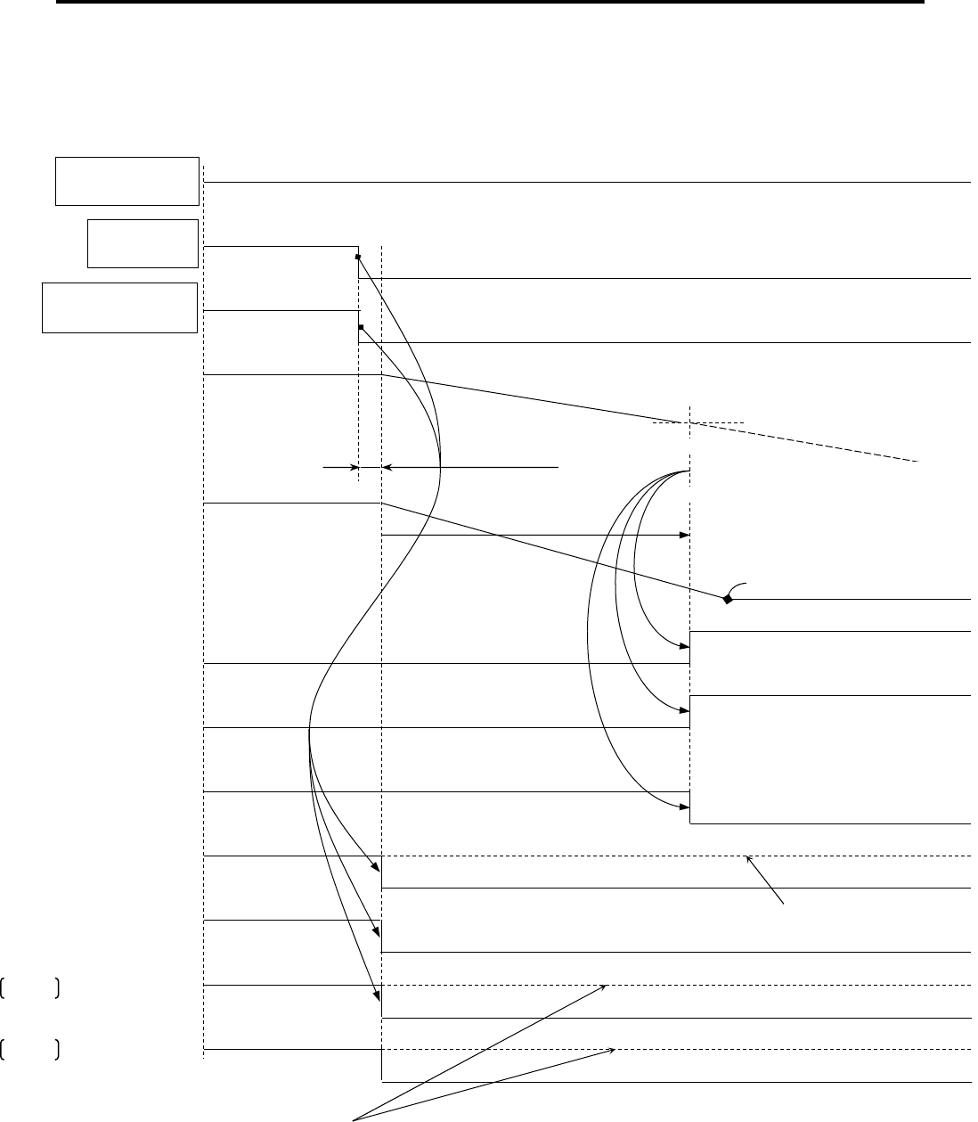
5. Operations
5-16
■ Main Circuit OFF, Quick STOP (Emergency STOP) Sequence
1. When motor did not stop with the setting value of the holding brake engage starting time, or main circuit
voltage drop is detected
CSP, CSV,
CST, PT
PP, PV
Power outage detection
delay time
1: Command enable
0: Command disable
(0x2100.6)
(Command
updates enable)
Holding brake start engage time
BONBGN:0x2026
Motor velocity
Quick Stop Active
(0x6041.5)
1 Quick Stop Active: 0
Dynamic brake signal
(DBON)
DB engagedDB released
Motor stoppage detection
:less than
50min
-1
Holding brake engaged
Holding brake control
(0x2100.4)
(HBON)
Holding brake released
Operation Enabled
(0x6041.2)
(Motor excitation signal)
Motor excitation releasedMotor excitation
Drive follows the
command value
(0x6041.12)
(Command
updates enable)
1: Command enable
0: Command disable
Main circuit power
Supply (R, S, T)
Main circuit ON Main circuit OFF
Main circuit voltage
Main circuit
charging
Voltage Enable
(0x6041.4)
0
1
Quick Stop
(0x6040.2)
1
Enable operation
(0x6040.3)
1: Servo ON
0: Emergency STOP
Main circuit voltage drop detection level
In the quick stop, "Drive follows the command value (Command updates enable)" becomes command invalid b
y
release of the quick stop signal.
or
Except quick stop

5.5 Operation Sequence
5-17
5
O
p
erations
■ Main Circuit OFF, Quick STOP (Emergency STOP) Sequence
2. When motor is stopped within holding brake start engage time or before main circuit voltage drop detection
In the quick stop, "Drive follows the command value (Command updates enable)" becomes command
invalid by release of the quick stop signal.
CSP, CSV,
CST, PT
PP, PV
Motor velocity
Quick Stop Active
(0x6041.5)
1 Quick Stop Active: 0
Dynamic brake signal
(DBON)
DB engagedDB released
Holding brake engaged
Holding brake control
(0x2100.4)
(HBON)
Holding brake
released
Operation Enabled
(0x6041.2)
(Motor excitation signal)
Motor excitation released
Motor excitation
Drive follows the
command value
(0x6041.12)
(Command
updates enable)
1: Command
enable
0: Command disable
Main Circuit
Power
Supply(R, S, T)
Main Circuit ON
Main circuit voltage
Main circuit
charging
Voltage Enable
(0x6041.4)
1
0
Quick Stop
(0x6040.2)
1
Enable operation
(0x6040.3)
1: Servo ON
0: Emergency Stop
Holding brake start engage time
BONBGN: 0x2026
Motor stoppage detection: less than
50min
-1
Main circuit voltage drop detection level
Holding brake engage delay time
BONDLY: 0x2024
Except Quick Stop
Main Circuit OFF
Power outage detection
dela
y
time
1: Command enable
0: Command disable
(0x6041.12)
(Command
updates enable)

5. Operations
5-18
5.5.2 Alarm Occurrence Stop Sequence
Servo motor is stopped by dynamic brake or servo brake with alarm occurrence. To stop either
with dynamic brake or servo brake, please refer to “Movement of SB, DB at the time of Alarm
detection” in the alarm code list. (SB: Servo brake Stop, DB: Dynamic brake Stop)
The stop method can be selected with Quick Stop option code (0x605A) for alarms that can be
stopped with the servo brake. Please refer to “Alarm Display List (11-3)” for details.
■ Stop Sequence with Dynamic brake at Alarm Occurrence
CSP, CSV,
CST, PT
PP, PV
Motor velocity
Dynamic brake signal
(DBON)
DB engagedDB released
Holding brake engaged
Holding brake control
(0x2100.4)
(HBON)
Holding brake
released
Operation Enabled
(0x6041.2)
(Motor excitation signal)
Motor excitation released
Motor excitation
Drive follows the
command value
(0x6041.12)
(Command
updates enable)
1: Command enable
0: Command disable
Main circuit power
Supply(R, S, T)
Main circuit ON
Enable operation
(0x6040.3)
1: Servo ON
Error Occur
(Monitor 0x6041.3)
0 1: Alarm Status
1: Command enable
0: Command disable
(0x2100.6)
(Command updates
enable)

5.5 Operation Sequence
5-19
5
O
p
erations
■ Stop Sequence with Servo Stop (Fault Reaction code) at Alarm Occurrence
1. When a motor does not stop with the setting value of holding brake engage start time
✔ Sequence above is in case that safety circuit is prepared.
Refer the section 4.1.6 and prepare safety circuit.
CSP, CSV,
CST, PT
PP, PV
Motor velocity
Dynamic brake signal
(DBON)
DB engagedDB released
Holding brake engaged
Holding brake control
(0x2100.4)
(HBON)
Holding brake released
Operation Enabled
(0x6041.2)
(Motor excitation signal)
Motor excitation released
Motor excitation
Drive follows the
command value
(0x6041.12)
(Command
updates enable)
1: Command enable
0: Command disable
Main circuit power
supply (R, S, T)
Main circuit ON
Enable operation
(0x6040.3)
1: Servo ON
Error Occur
monitor0x6041.3
0
1: Alarm status
Motor stoppage detection
:less than 50min
-1
Holding brake start engage time
BONBGN:0x2026
(0x2100.6)
(Command
updates enable)
1: Command enable
0: Command disable

5. Operations
5-20
■ Stop Sequence with Servo Stop (Quick Stop option code) at Alarm Occurrence
2. When a motor has stopped with the setting value of holding brake engage start time
CSP, CSV,
CST, PT
PP, PV
Motor velocity
Dynamic brake signal
(DBON)
DB engagedDB released
Holding brake engaged
Holding brake control
(0x2100.4)
(HBON)
Holding brake released
Operation Enabled
(0x6041.2)
(Motor excitation signal)
Motor excitation
released
Motor excitation
Drive follows the
command value
(0x6041.12)
(Command
updates enable)
1: Command enable 0: Command disenable
Main circuit power
supply(R, S, T)
Main circuit ON
Enable operation
(0x6040.3)
1: Servo ON
Error Occur
(monitor0x6041.3
0
1: Alarm status
Holding brake engage delay time
BONDLY: 0x2024
Holding brake start engage time
BONBGN:0x2026
Motor stoppage detection
: 50min
-1
or less
1: Command enable 0: Command disenable
(0x2100.6)
(Command
updates enable)

5.5 Operation Sequence
5-21
5
O
p
erations
5.5.3 Alarm Reset Sequence
Alarm can be reset by inputting alarm reset signal from generic input signals.
✔ Power reset (Turn off power once and re-input) or encoder clear is required for the alarm reset depending
on alarm type. Refer to section “8.2 Warning and Alarm List” for details.
✔ Confirm that there is no alarm by checking alarm signal, and then cancel alarm reset signal. Alarm signal
is not able to cancel if alarm state is continuing so it shall be returned to zero state after timeout 20ms or
more. Moreover, alarm reset signal shall be input 20ms or more when inputting without alarm signal
confirmation.
Alarm reset
(0x6040.7)
Alarm signal
(0x6041.3)
1: Alarm reset
Main circuit power
Supply(R, S, T)
Main circuit power ON
Switch On
(0x6041.1)
1: Operation preparation completed
0
Enable operation
(0x6040.3)
0: Servo OFF
1: Servo ON
1:
A
larm status
Power ON
enable signal
Power ON signal
(0x6041.4)
Inrush current protection time
1: Power ON enabled
0: Alarm cancelled
Alarm reset input 20 ms or more

5. Operations
5-22
5.6 Communication timing
Since application is synchronized with master and slave, data handling of EtherCAT makes a peculiar motion.
As for synchronization type, synchronization mode discernment is possible by the combination of 0x1C32 and
0x1C33 of sub index in Object Dictionary. Terms used to Communication Timing are explained below.
Copy and Prepare Outputs
Output data in trigger events, such as local timer event and SM2/3 event and SYNC0/1 event, are read from
SyncManager output area. Then, slave operates process using output data, and is outputted to motor.
The overview of "Copy and Prepare Output" time is the hardware delay depending on the time and software
operating time for copying process data to a local memory from SyncManager, when accurate operation move is
required. They follow the value described by SyncManager Object: 0x1C32.
Index Sub-Index Time Definition
0x1C32 0x06 Process data copy from SyncManager and accurate operation
0x1C32 0x09 Hardware Delay Time
Get and Copy Inputs
The abstract of "Get and Copy Inputs" time is the delay for copying input process data to hardware reading of a
encoder signal and SyncManager 3 area, when accurate operation move is required. They follow the value
described by SyncManager Object: 0x1C33.
Input can be used in SyncManager 3 area after 0x1C32 and 0x05 "Minimum Cycle Time".
Index Sub-Index Time Definition
0x1C33 0x06 Data copy from accurate operation and local memory to SyncManager
0x1C33 0x09 Hardware delay time for input latch preparation
Outputs Valid
"Outputs Valid" in RS2-EtherCAT slave amplifier indicates the time, which added together the following three
kinds of time.
1) Time until copies process data to local memory from SyncManager by trigger event
2) Time until servo loop operation process and the current command to ASIC for servo are written in
3) Hardware delay to current loop operation process within ASIC and IGBT gate output
Start Driving Outputs
"Start Driving Outputs" is the timing to write current command in ASIC for servo by microcontroller.
0x1C32 and 0x09 "Hardware Delay Time" indicate between "Start Driving Outputs" and "Outputs Valid".
Start Latch
"Start Latch" is start signal to input latch process.
Between "Start Latch" and "Input Latch", defines as 0x1C33 and 0x09:"Delay Time" in consideration of hardware
delay time and the software operating time mounted in slave.
Input Latch
"Input Latch" in RS2-EtherCAT slave amplifier indicates the real position acquisition timing of motor encoder.
However, when position cannot be received more correctly than encoder (serial encoder), data is not copied to
SyncManager area.
User Shift Time
"User Shift Time" is value in consideration to the jitter of the master.
SYNC1 Cycle Time
"SYNC1 Cycle Time" may be used for the shift of "Start Input Latch" or "Start Driving Output". "SYNC1 Cycle
Time" is defined as a register 0x984 - 0x987 as a shift time between SYNC0 and SYNC1, as long as SYNC0 is a
standard signal.
Shift Time
"Shift Time" defines time between the synchronous event such as SM2 event, SYNC0, and SYNC1, and also
"Outputs Valid" and "Input Latch". Possible to write if its specifications can shift "Outputs Valid" or "Input Latch".

5.6 Communication timing
5-23
5
O
p
erations
5.6.1 Free Run Mode (Free Run: Asynchronous Operation)
In free run mode, starts by the local timer interrupt of an application controller.
Local cycle moves independently of communication cycle or master cycle.
As an optional feature, slave supports 0x02 of 0x1C32 "Cycle Time". In this case, 0x05 of 0x1C32 "Minimum Cycle Time" is also
supported with slave.
Free run mode is set as 0x1C32:0x01=0x00 and 0x1C33:0x00=0x00.
Parameter of Free Run Mode List
Index Sub-Index Dir Name Remarks
0x1C32 0x01
RW
Synchronization Type 0x00:Free Run Support
0x02
RO
Cycle Time Control Cycle Time of Slave
0x04
RO
Synchronization Type Supported Bit0=1:FreeRun Support
0x05 RO Minimum Cycle Time R 3E Model EtherCAT(s) are the same setup to 0x1C32:0x02.
0x1C33 0x01
RW
Synchronization Type 0x00:Free Run Support
0x02
RO
Cycle Time Same setup to 0x1C32:0x02
0x04
RO
Synchronization Type Supported Same setup to 0x1C32:0x04
0x05 RO Minimum Cycle Time Same setup to 0x1C32:0x05
Communication Timing of Free Run Mode
Local Cycle Time Event Local Cycle Time Event
0x1C32,0x02:Cycle Time
0x1C32,0x05:Minimum Cycle Time
Output Valid
Copy and Prepare Outputs
Input Latch
Get and Copy Input

5. Operations
5-24
5.6.2 DC Mode (SYNC0 Event Synchronization)
Local cycle of slave is started to SYNC0 event reception.
Process data frame must complete data reception within slave before the next SYNC0 interruption generating.
"Calc and Copy Time" contains the minimum time lag between frame reception and SYNC0 event.
Parameter of DC Mode (SYNC0 Event Synchronization)
Index Sub-Index Dir Name Remarks
0x1C32 0x01
RW
Synchronization Type Synchronized with 0x02:DC SYNC0
0x02
RO
Cycle Time SYNC0 Cycle Time
0x04
RO
Synchronization Type Supported Bit4:2=001:DC SYNC0
0x05
RO
Minimum Cycle Time
0x06
RO
Calc and Copy Time Minimum Time between Frame and SYNC0
0x08
RW
Cycle Time Acquisition
0x09
RO
Delay Time
0x0B
RO
Cycle Time Short
0x0C
RO
SM Event Missed(Event Omission)
0x0E
RO
RxPDO Toggle Failed
0x20 RO Synchronization Error
0x1C33 0x01
RW
Synchronization Type Synchronized with 0x02:DC SYNC0
0x02
RO
Cycle Time Same set to 0x1C32:0x02
0x04
RO
Synchronization Type Support Same set to 0x1C32:0x04
0x05
RO
Minimum Cycle Time Same set to 0x1C32:0x05
0x06
RO
Calc and Copy Time Time between Input Latch and Minimum Cycle Time
0x08
RW
Cycle Time Acquisition Same set to 0x1C32:0x08
0x0B
RO
Cycle Time Short Same set to 0x1C32:0x0B
0x0C
RO
SM Event Missed(Event Omission) Same set to 0x1C32:0x0C
0x0E
RO
RxPDO Toggle Failed Same set to 0x1C32:0x0E
0x20 RO Synchronization Error Same set to 0x1C32:0x20
Communication Timing of DC Synchronization Mode (SYNC0)
SYNC0 Event
0x1C32,0x02:Cycle Time
0x1C32,0x05:Minimum Cycle Time
Output Valid
0x1C33,0x06
Calc and Copy Time
Frame
0x1C32, 0x06
Calc and Copy Time
Input Latch
0x1C32,0x09
DelayTime(Hardware Delay)
SM2 Event
Frame
SM2 Event SYNC0 Event
Frame
Frame

5.6 Communication timing
5-25
5
O
p
erations
5.6.3 DC Mode (SYNC1 Event Synchronization)
Local cycle of slave is started to SYNC0 event reception.
Should receive process data frame before the next SYNC0 interruption generating.
Since SYNC1 is used for "Output Valid", SYNC1 cycle time defines the time lag between SYNC0 and "Start Driving
Output".
0x1C32 and 0x06 (Calc and Copy Time) indicate the allowance time for SYNC1 cycle time, and 0x1C32 and 0x09
(Delay Time) define the hardware delay for driving an output.
Parameter of DC Mode (SYNC1 Event Synchronization)
Index Sub-Index Dir Name Remarks
0x1C32 0x01 RW Synchronization Type Synchronized with 0x03:DC SYNC0
0x02 RO Cycle Time SYNC0 Cycle Time
0x04
RO
Synchronization Type
Supported
Bit4:2=010:DC SYNC1
0x05 RO Minimum Cycle Time
0x06 RO Calc and Copy Time
Value between SYNC0 and Minimum SYNC1 Cycle Time
0x08 RW Cycle Time Acquisition
0x09 RO Delay Time
0x0B RO Cycle Time Short
0x0C
RO
SM Event Missed(Event
Omission)
0x0E RO RxPDO Toggle Failed
0x20 RO Synchronization Error
0x1C33 0x01 RW Synchronization Type Synchronized with 0x03:DC SYNC1
0x02 RO Cycle Time Same set to 0x1C32:0x02
0x04
RO
Synchronization Type
Supported
Same set to 0x1C32:0x04
0x05 RO Minimum Cycle Time Same set to 0x1C32:0x05
0x06 RO Calc and Copy Time Time between Input Latch and Minimum Cycle Time
0x08 RW Cycle Time Acquisition Same set to 0x1C32:0x08
0x0B RO Cycle Time Short Same set to 0x1C32:0x0B
0x0C
RO
SM Event Missed(Event
Omission)
Same set to 0x1C32:0x0C
0x0E RO RxPDO Toggle Failed Same set to 0x1C32:0x0E
0x20 RO Synchronization Error Same set to 0x1C32:0x20
Communication Timing of DC Synchronization Mode (SYNC0)
SYNC0 Event
0x1C32,0x02:Cycle Time
0x1C32, 0x05:Minimum Cycle Time
Output Valid
0x1C33, 0x06
Calc and Copy Time
0x1C32, 0x06
Calc and Copy Time
Input Latch
0x1C32, 0x09
DelayTime(Hardware Delay)
Frame
Frame
SYNC0 Event
SYNC1 Cycle Time
SYNC1 Event
SYNC1 Event

5. Operations
5-26
5.7 PDS FSA
5.7.1 Abstract
PDS (Power System Device) FSA (Finite States Automaton)of the EtherCAT slave amplifier is an abstract concept which defines the
state of the control device stays or passes, operation with the Black Box. It defines the slave's application operating. Slave controls
State Device, Mode, and State Change with Object "Control Word (0x6040)" sent via the network.
By "Status word (0x6041)" generated with slave device, the State returns the present state. Besides, PDS and FSA are controlled also
by Error Detection Signal.
The slave local and network shows you how to be driving.
Control Word / Status Word Concept of Slave
PDS FSA
Device Control/Function Block
Operation Mode
State Machine
(State Change)
Status Word
(0x6041)
Control Word
(0x6040)
Logic Operation
Local Signal
Local/Remote Switch
Error Detection
Status within Slave

5.7 PDS FSA
5-27
5
O
p
erations
5.7.2 FSA(Finite States Automaton)
FSA of RS2 EtherCAT slave amplifier determines the sequence of device state and drive control, and operation peculiar to each state
is shown.
With this State Machine, what kind of command slave amplifier receives is changed.
FSA of RS2 EtherCAT Amplifier
Low Level power Area
: The control source is established and the state can switch on main circuit power supply.
High Level Power Area
: Main circuit power supply is in SwithOn state. However, motor is in servo-off (torque(force)-off) state, and when the
main circuit is not established, Shift 3 is canceled by slave. Target and set point value are invalid.
Torque Area
: After slave completes servo-on (torque(force)-on) preparation, excited by motor with SwithOn.
Motor is operated by target or set point value.
Not ready to
Switch on
Switch on
Disabled
Ready to
Switch on
Switched on
Operation
enabled
Quick stop
active
Fault reaction
active
Fault
0
1
7 2
10
12
13
15
14
11
16
3
4 5
6
8
9
Erro
Start
Power Off or Reset
Low Level powe
r
High Level powe
r
Torque
Torque on the Motor enabled
High level power enabled
No Torque on the Moto
r
Power or control unit enabled
High level power can be enabled
A
B
C
D
E F
G
H

5. Operations
5-28
FSA and FSA state describes the state transitions.
FSA State Definition
No. State Description
[A] Not Ready to Switch on The control source is provided to the slave and established.
Slave is performing initialization or self-test.
[B] Switch on Disabled Initialization is completed, and slave is in condition to be able to set parameter.
However, main circuit power supply is not in the state should be supplied.
[C] Ready to Switch on In input permission state about main circuit power supply.
Although parameter can be set, function is in invalid state.
[D] Switch on
Main circuit power supply is provided and in the completion state of
Operation enabled preparation. Parameter to slave can be set.
This amplifier is
able to transit even if main power is OFF.
[E] Operation Enabled Fault (alarm) is not generated, where drive function is effective and motor is excited.
Parameter to slave can be set.
[F] Quick Stop Active In the state where the Quick stop (scram) function is performed.
In the state where drive function is effective and motor is excited.
[G] Fault Reaction Active In the state where Fault (alarm) occurs with slave and the Quick stop (scram) function is
performed. Also, in the state that motor is excited by the drive function effective.
[H] Fault In the state which the fault (alarm) generated with the slave and Fault reaction completed.
Drive function is invalid, and main circuit power supply is turned on or off by application.

5.7 PDS FSA
5-29
5
O
p
erations
State Shift of FSA
No. [Before Shift]->[After] Event / Action
0
[Start]
[Not ready to Switch on]
Event : After control power supply ON or reset application, shifts automatically.
Action : Slave performs initialization and self-test.
1
[Not ready to Switch on]
[Switch on Disabled]
Event : Shifts automatically.
Action : Communication is permitted.
2
[Switch on Disabled]
[Ready to Switch on]
Event : [Shut down] command (Bit2, 1, 0=1, 1, 0) is received from master.
Action : None
3
[Ready to Switch on]
[Switch on]
Event : [Switch On] command (Bit3, 2, 1, 0=0, 1, 1, 1) is received from master.
Action : Since in main circuit power supply permission state, provide main circuit power
supply.
4
[Switch on]
[Operation enabled]
Event : [Enable operation] command (Bit3, 2, 1, 0=1, 1, 1, 1) is received from master.
Action : Slave is Servo-ON and all the internal preset values are cleared.
5
[Operation enabled]
[Switch on]
Event : [Disabled operation] command (Bit3, 2, 1, 0=0, 1, 1, 1) is received from master.
Action : Slave is Servo-ON.
6
[Switch on]
[Ready to Switch on]
Event : [Shut down] command (Bit2, 1, 0=1, 1, 0) is received from master.
Action : Master should intercept main circuit power supply.
7
[Ready to Switch on]
[Switch on Disabled]
Event : [Quick Stop] command (Bit2, 1=0, 1) or
[Disable voltage] command (Bit1=0) is received from master.
Action : None
8
[Operation enabled]
[Ready to Switch on]
Event : [Shut down] command (Bit2, 1, 0=1, 1, 0) is received from master.
Action : Slave is Servo-Off. Master should intercept main circuit power supply.
9
[Operation enabled]
[Switch on Disabled]
Event : [Disable voltage] command (Bit1=0) is received from master.
Action : Slave is Servo-Off. Master should intercept main circuit power supply.
10
[Switch on]
[Switch on Disabled]
Event : [Quick Stop] command (Bit2, 1=0, 1) or
[Disable voltage] command (Bit1=0) is received from master.
Action : Master should intercept main circuit power supply.
11
[Operation enabled]
[Quick stop active]
Event : [Quick Stop] command (Bit2, 1=0, 1) is received from master.
Action : Quick Stop function is performed.
12
[Quick stop active]
[Switch on Disabled]
Event : Shifts automatically when Quick Stop operation is completed or when the "Disable
voltage" command (Bit1=0) is received at Quick Stop option code 1-3.
Action : Slave is Servo-Off. Master should intercept main circuit power supply.
13
Error occurs
[Fault reaction active]
Event : Fault (Alarm) occurs at slave.
Action : Set-up Fault operation function is performed.
14
[Fault reaction active]
[Fault]
Event : Shifts automatically.
Action : Slave is Servo-Off. Master should intercept main circuit power supply.
15
[Fault]
[Switch on Disabled]
Event : [Fault reset] command (Bit7=0 -> 1) is received from master.
Action : Without slave's Fault factor, Fault reset is performed.
Master should clear the "Fault reset" bit (Bit7=1->0) after normal state check.
16
[Quick stop active]
[Operation enabled]
Event : [Enable operation] command (Bit3, 2, 1, 0=1, 1, 1, 1) is received by Quick Stop
option code5 to 7.
Action : Slave function is permitted.

5. Operations
5-30
5.8 Operation Mode
5.8.1 Kinds of operation mode
■ Operation mode list
EtherCAT-CoE specification has modes of operation shown in operation mode list.
Profiles applicable to R 3EModel EtherCAT-CoE slave amplifier are listed in the following Operation Mode List.
Besides, operation mode supported can check at "Supported Drive Mode:0x6502."
Operation Mode List
Operation Mode Mark
R 3EModel
EtherCAT Supported
Profile Position Mode pp Yes
Profile Velocity Mode pv Yes
Homing Mode hm Yes
Interpolated Position Mode ip Yes
Torque (force) Mode tq Yes
Velocity Mode (ex. Inverter) vl No
Cycle Sync. Position Mode csp Yes
Cycle Sync. Velocity Mode csv Yes
Cycle Sync. Torque (force) Mode cst Yes
Shift of an operation mode uses the object "operation mode:0x6060."
Also, the object "operation mode display:0x6061" is used for the present operation mode check.
At each operation mode, the bit assigned to Control Word and Status Word is prepared.
Unique Mode Bit Assigned to Control Word
Operation Mode bit8 bit6 bit5 bit4
pp Profile Position Mode
Absolute / Relative Position
Change set immediately New set point
csp Cycle Sync. Position Mode Reserved Reserved
ip Interpolated position Reserved Reserved
Interpolation
Enable
csv Cycle Sync. Velocity Mode Reserved Reserved Reserved
pv Profile Velocity Mode Halt Reserved Reserved Reserved
cst
Cycle Sync. Torque
(force) Mode
Homing offset Active Reserved Homing Enable
tq Torque (force) Mode
hm Homing Mode
Unique Mode Bit Assigned to Status Word
Operation Mode bit13 bit12 bit10
pp Profile Position Mode Following error Set-point Acknowledge
Target reached
Quick Stop Finished
Operation Change Finished
Halt Active
csp
Cycle Sync. Position
Mode
Following error Target Position ignore
ip Interpolated position Reserved Interpolation active
csv
Cycle Sync. Velocity
Mode
Reserved Target velocity ignore
pv Profile Velocity Mode
cst
Cycle Sync. Torque
(force) Mode
Reserved Target torque (force) ignore
tq
Torque
(force) Mode
hm Homing Mode Homing error Homing attained
Selection and change of an operation mode use mode: 0x6060 of operation, and mode display: 0x6061 of operation is
used for the check of the operation mode under present operation.

5.8 Operation Mode
5-31
5
O
p
erations
5.8.2 Function Group "Position" Mode
■ Abstract of Function Group “Position” Mode
As for function group “Position” operation mode, “Profile position Mode”, “Cyclic Synchronous Position Mode” and “Interpolated
Position Mode”are supported. 0x6060: Operate “Profile Position Mode” by setting “1” in operation mode, “Cyclic Synchronous Position
Mode” by setting “8” and “Interpolated Position Mode” by setting “7”.
Here is the main object list for the function group “Profile Position Mode”
Block Diagram of each operation mode when the function group is in "Position" mode
1
8
7
0x6060
OperationMode
0x6062
PCValue
Position Command
Internal Value
Software
Position Limit
+
+
0x607A
TAPOS
Targe t
Position
0x60B0
POSOFF
Position
Offset
Cycle Synchronization Position Mode (csp)
0x6060:O
p
eration Mode 「8
」
0x607D,1
SMINLIM
0x607D,2
SMAXLIM
0x607B,1
MINPLIM
0x607B,2
MAXPLIM
Position
Range Limit
Software
Position Limit
Interpolation
Position
Targe t
0x60B0
POSOFF
Position
Offset
Interpolated Position Mode (ip)
0x60C1-0x1
IPPOS
FIFO buffer: max. 256
Ring buffer: max. 256
0x6040
Interpolation
Enable
0x6060:O
p
eration Mode 「7」
0x607D,1
SMINLIM
0x607D,2
SMAXLIM
0x607B,1
MINPLIM
0x607B,2
MAXPLIM
Position
Range Limit
+
+
Interpolation
Time
0x60C1-0x2
IPTIM
0x60C2
Interpolation
time period
Interpolation
time
period
0x60C0
Timing
Interpolation
sub mode select
0x607A
TAPOS
Targe t
Position
Profile Position Mode (pp)
Trajectory
generation
Profile
Acceleration
0x6083
TVCACC
0x6084
TVCDEC
0x6081
PROVEL
Profile
Velocity
0x607F
VCLM
Maximum Profile
Velocity
0x6060 : O
p
eration Mode
Software
Position Limit
0x607D,1
SMINLIM
0x607D,2
SMAXLIM
0x607B-1
MINPLIM
0x607B-2
MAXPLIM
Position
Range Limit
Profile
Deceleration
0x60A4-1
JERK1
0x60A4-2
JERK2
Profile
Jerk1
Profile
Jerk2
0x60A3
JERKUSE
Profile Jerk use
0x6086
MOTPRO
Motion
Profile Type

5. Operations
5-32
[Velocity feed forward]
[FF Vibration
suppression control]
[Position controller]
Velocit
y
command monitor
[Velocity
controller]
Torque command
monitor
Torque monitor
Velocity
monitor
for Incremental encoder
Each of monitors
Each of monitors
Analog monitor
output 2
Analog monitor
output 1
+
-
+
-
+
+
for Absolute encoder
[Feed forward control]
[Position command input process]
[Position control] [Torque control][Velocity control]
+
+
+
+
+ -
Block diagram of function group "position" mode
Without Model control
FFGN
[0x2008-1]
PCSMT
[0x2003]
SUPFRQA1
[0x2012-1]
SUPLVA
[0x202C]
SUPFRQB1
[0x2012-6]
SUPCRB
[0x2012-5]
Actual Position Deviation
Torque command
notch filter
Torque
control
TCNFILC
[0x2014-3]
TCNFDC
[0x202D-3]
TCNFILD
[0x2014-4]
TCNFDD
[0x202D-4]
TCNFILA
[0x2014-1]
TCNFPA
[0x202D-1]
TCNFILB
[0x2014-2]
TCNFDB
[0x202D-2]
VDFIL
[0x200A]
OSSFIL
[0x2018]
4-multiplier
MON1
[0x2023-1]
MON2
[0x2023-2]
KP1
[0x2005-1]
TPI1
[0x2006-1]
PLPHLK
[0x2061-1]
PLPHLF
[
0x2061-2
]
VCNFIL
[0x2013]
VCFIL
[0x2009]
KVP1
[0x200B-1]
TVI1
[0x200C-1]
JRAT1
[0x200D-1]
VLPHLK
[0x2062-1]
VLPHLF
[0x2062-2]
HKVIK
[0x2063-1]
HKVIF
[0x2063-2]
MAXTRQ
[0x6072]
TCLM-F
[0x60E0]
TCLM-R
[0x60E1]
CMDPOL
[0x607E]
Servo motor
Motor encoder
FFFIL
[0x2008-2]
Position deviation counter
FBHPLS
[0x2051-2]
FBHTIM
[0x2051-3]
[Velocity
detection]
TCNFILE
[0x2014-5]
TCNFDE
[0x202D-5]
Operation Mode
OPMODE
[0x6060]
Position command
Input Block
(Refer to preceding
page)
PCMON
[0x6062]
PMON
[0x60F4]
Position Demand Value
PCFIL
[0x2004]
TFFK
[0x2064-1]
TFFAVE
[0x2064
-
2]
[
Tor
q
ue feed forward
]
[Torque FF output selection]
[0x2064-3]
TCFIL1
[0x2011-1]
TCFILOR
[0x202B]
Preset Actual Position
IACPMON
[0x6063]
Actual Position
APMON
[0x6064]
Z Phase Standard
Actual Position
CCUNIT
[0x2105]
Control Effort
VCMDPO
[0x60FA]
CMDPOL
[0x607E]
Scale
setting
(Refer to
chapter
5.13)
Position
deviation
counter
PDEVMON
[0x20F1-3]
Torque command monitor
(before filter)

5.8 Operation Mode
5-33
[Model following control / Model following vibration suppression control] [Position command input process]
[Model velocity feed forward]
[FF Vibration
suppression
control]
+
-
[Position controller]
Velocit
y
command monitor
[Velocity
controller]
Torque command monitor
Torque monitor
Velocity
monitor
Each of monitors
Each of monitors
Analog monitor
output 2
Analog monitor
output 1
+
-
+
-
+
-
+
-
+
+
for Absolute encoder
[Model velocity
control]
[Position control] [Torque control] [Velocity control]
[Machine model]
(Model following
control
)
(Model following
vibration suppression
control)
Block diagram of function group "position" mode with Model following control / Model following vibration suppression control
With Model following
control / Model
following vibration
suppression control
PCFIL
[0x2004]
MTFFD
[0x2068-3]
MFFGN
[
0x2068-2
]
TRCPGN
[0x2007]
Position deviation counter
MZETA
[0x2068-1]
MAXTRQ
[0x6072]
TCLM-F
[0x60E0]
TCLM-R
[0x60E1]
TCFIL1
[0x2011-1]
PCSMT
[0x2003]
SUPFRQA1
[0x2012-1]
SUPLVA
[0x202C]
SUPFRQB1
[0x2012-6]
SUPCRB
[0x2012-5]
Actual Position Deviation
Torque command
notch filter
TCFIL1
[0x2011-1]
TCFILOR
[0x202B]
Torque
control
TCNFILC
[0x2014-3]
TCNFDC
[0x202D-3]
TCNFILD
[0x2014-4]
TCNFDD
[0x202D-4]
TCNFILA
[0x2014-1]
TCNFPA
[0x202D-1]
TCNFILB
[0x2014-2]
TCNFDB
[0x202D-2]
VDFIL
[0x200A]
OSSFIL
[0x2018]
4 逓倍
or Incremental encoder
MON1
[0x2023-1]
JRAT1
[0x200D-1]
ANRFRQ1
[0x2019-1]
RESFRQ1
[0x201A-1]
MON2
[0x2023-2]
KP1
[0x2005-1]
TPI1
[0x2006-1]
PLPHLK
[0x2061-1]
PLPHLF
[
0x2061-2
]
VCNFIL
[0x2013]
VCFIL
[0x2009]
KVP1
[0x200B-1]
TVI1
[0x200C-1]
JRAT1
[0x200D-1]
VLPHLK
[0x2062-1]
VLPHLF
[0x2062-2]
HKVIK
[0x2063-1]
HKVIF
[0x2063-2]
MAXTRQ
[0x6072]
TCLM-F
[0x60E0]
TCLM-R
[0x60E1]
CMDPOL
[0x607E]
Servo motor
Motor encoder
Velocity
detection
MFFFIL
[0x2068-4]
Position deviation counter
Position deviation counter
FBHPLS
[0x2051-2]
FBHTIM
[0x2051-3]
[Velocity
detection]
TCNFILE
[0x2014-5]
TCNFDE
[0x202D-5]
Operation Mode
OPMODE
[0x6060]
Position command
Input Block
(Refer to preceding
page)
JRAT1
[0x200D-1]
PCMON
[0x6062]
PMON
[0x60F4]
Position Demand Value
KM1
[0x2017-1]
Scale
setting
(Refer to
chapter
5.13)
CMDPOL
[0x607E]
Torque command monitor (before filter)

5. Operations
5-34
■ Profile Position mode
0x6060: When Operation Mode is set “1”, “Profile Position Mode” shall be operated.
The master sends “Target Position (0x607A)”, “Profile Velocity (0x6081), “Profile Acceleration
and Deceleration (0x6083,0x6084).
The slave (servo amplifier) executes trajectory generation and starts to move to the target position by setting
bit4=1:New set-point of Control word 0x6040.
The slave executes all of Position Control, Velocity control, and Torque (force) control.
Also, Velocity offset and Torque (force) offset can be used as Velocity Additional value and Torque (force)
Additional value.
The following two different ways to apply to a servo amplifier supported by device profile.
There are two different ways as follows to set target positions to a servo amplifier supported by the device profile.
1. Single set point: [Change set immediately bit(0x6040:Control word bit5) = 1]
During the set point processing, if a new set-point is set by “New set-point (bit 4)” in Control word, the servo amplifier immediately
processes the new set-point.
For relative position move, new set-point will be as relative move value from processing point. In this case, please make not to exceed
maximum value (0x7FFFFFFF) by sum of processing point and new set-point move value.
2. Set of set points: [Change set immediately bit(0x6040:Control word bit5) = 0]
During the set point processing, if a new set-point is set by “New set-point (bit 4)” in Control word,
the servo amplifier immediately processes the new set-point after reaching the target position.
The master controller switches the two modes mentioned above by the timing of the following bits;
“New set-point(bit4)”, ”Change set immediately(bit5)”, ”Change of set-point(bit9)” in the Control Word (0x6040)and
“Set-point acknowledge(bit12
)” in the Status Word (0x6041).
These bits allow to set up a request response mechanism in order to prepare the next set points
while a previous set point still is processed in the servo amplifier.
This minimizes reaction times within a control program on the master.
Sequence Diagram for Profile Position Mode
New set-point
(0x6040:bit4)
Set-point
Change set immediately
(0x6040:bit5)
Set-point acknowledge
(0x6041:bit12)
②
③
Target reached
(0x6041:bit10)
Bufferd set-point
Processed set-point
A
B C D E
B C C
A
A
B B B E
① ④ ⑤
t
t
t
t

5.8 Operation Mode
5-35
5
O
p
erations
& Single set-point
(1) If the bit “Change set immediately (bit5)” is “1”, a single set point is executed by the servo amplifier.
(2) After a set point is applied to a servo amplifier, the master sets “new set-point (bit4)” in Control word to “1”
in order to notify completion of the set point to the slave (servo amplifier).
(3) A slave (servo amplifier) acknowledges a requested bit and buffers a new set-point, and in order to respond,
sets “Set-point acknowledge (bit12)” to “1”.
(4) After the master recognized the new valid data, “New set-point (bit4)” is released to “0”.
(5) Even if the set point that is received at the time point “t0” is being processed, a new set-point will be immediately valid.
(6) The servo amplifier validates the actual move to the new target position immediately when the second target position as
“New set-point” at the time point “t1” is received.
Single set-point (Update a set point immediately)
◆ Position command error 1 (AL_D2) alarm will be issued if a recalculated position by "Change set immediately (bit5)" on linear
coordinate system exceeds a limit of position range.
v1
t0
0x6083
Time
Velocity
t1
t3
0x6084
v2
New set-point
(0x6040:bit4)
Current
target position
processed
Target position
(set-point)
Set-point
acknowledge
(0x6041:bit12
)
Target reached
(0x6041:bit10)

5. Operations
5-36
& Set of set-points
(1) If the bit “Change set immediately (bit5)” is “0", the servo amplifier executes settings for the set-point.
(2) After a set point is applied to a servo amplifier, the master sets “new set-point (bit4)” in Control word to “1” in order to notify
completion of the set point to the slave(servo amplifier).
(3) A slave(servo amplifier) acknowledges a requested bit and buffers a new set-point, and in order to respond, sets “Set-point
acknowledge(bit12)” to “1”.
(4) After the master recognized the new valid data, “New set-point (bit4)” is released to “0”.
(5) A new set-point will be valid after completion of a Set-point processing received at the time point “t0”.
(6) The servo amplifier validates the actual move to the new target position ”t3” immediately as long as that receives the second target
position as “New set-point” before arriving to the first target position “t1”.
(7) When the bit Change of set-point (bit 9)" is set to “1”, the servo amplifier moves to the next set-point processing
without reducing the velocity once to Zero during set-point processing.
Set of set points (Update to the next set point after completion of a set point)
v1
t0
0x6083
Time
Velocity
t1
t2
t3
0x6084
v2
Profile of Change of set-point(bit9)= When the bit "1" is set
New set-point
(0x6040:bit4)
Current
target position
processed
Target position
(set-point)
Set-point
acknowledge
(0x6041:bit12)
Target reached
(0x6041:bit10)

5.8 Operation Mode
5-37
5
O
p
erations
0x6040:Control Word (Profile Position Mode: pp)
Index 0x6040
This object shall indicate Operation Mode Specific bit and Manufacture
r
specific bit of Profile Position Mode (pp).
Object Code Variable
Sub-Idx Description Data Type Access PDO Initial value
0x00 Control Word [CWORD]
* See the Command table for “Control word bit
pattern (Bit 7, 3, 2,1, 0,)
Unsigned16 RW Possible 0x0000
Range 0x0000-0xFFFF
MSB LSB
Cseten - Eclr -
Change of
set-point
Halt
Fr
*
Abs / Rel
Change set
immediately
New
Set point
Hs
*
qs
*
ev
*
so
*
15 14..13 12 11..10 9 8 7 6 5 4 3 2 1 0
bit6:ABS/REL [ABS/REL]
0:Target position (0x607A) is an absolute value
1:Target position (0x607A) is a relative value
bit8:HALT [HALT]
0:Activate Profile Position Positioning process
1:Stop axle with halt option code(0x605D)
bit5:Change set immediately [Change set immediately]
Used for changing the target position during operation.
If this bit is set to 1, and bit 4 is changed “Zero” to “One” again, the
trajectory generation to the new set point shall be processed
immediately. All previously loaded set points shall be discarded.
Bit9: Change of set point [Change of set point]
This bit9 is used for the slave (servo amplifier) that moves to
the next set-point processing without reducing the velocity once to
Zero during set operation of set point.
1: Set point processing without reducing the velocity to Zero.
bit4:New set point [New setpoint]
0:Does not assume target position
1:Assume target position
Set "1" to this bit after change of bit6 of status word 1 from "0" to "1".

5. Operations
5-38
0x6041:Status Word (Profile Position Mode: pp)
Index 0x6041
This object indicates Operation Mode Specific bit and
Manufacturer Specific bit of the Profile Position mode (pp).
Object code Variable
Sub-Idx Description Data Type Access PDO Initial value
0x00 Status Word [STSWORD]
* See the Pattern Status table for “Status word bit pattern
(Bit 6,5, 3,2,1,0,)
Unsigned16 RO Possible 0x0000
Range 0x0000-0xFFFF
MSB LSB
Csetfix Csetpro
Fe
Set-point
Acknowledge
Internal
Limit active
Tr Rm Res W Sod
*
Qs*
Ve F*
Oe*
So*
Rtso*
15 14 13 12 11 10 9 8 7 6 5 4 3 2 1 0
bit4:Voltage Enabled [Voltage Enabled]
0:Voltage disenabled 1:Voltage enabled
bit9:remote [remote]
0: Control word is not processed
1: Being processed by control word
bit10:Target reached [Target reached]
1: Reached at target position
Set to “1” when the actual position in “in-position” range after internal
command generated from start-up profile reached at target position.
Also set to "1" in the halt state, when quick stop operation activated
(quick stop option code-2, 5, 6, and 7), and operational mode change
completed (for about 1 sec set) .
*This bit won't change to 1, while New setpoint of the control word is 1.
bit7:warning [warning]
0:No warning 1:Warning condition
bit13:Following error [Following error]
0:No following error 1:Following error
bit11:Internal limit active [Internal Limit active]
0:In normal operation, or standby state after previous normal profiling.
1:Set in the following cases.
・When relative position command selected and wrap around inactivated,
the value oversteps the coordinate from positive (present position ≦
0x7FFFFFFF) to negative (0x80000000 ≦target position), or from negative
(0x80000000≦present position) to positive (target position≦0x7FFFFFFF).
・When operation not started in the procedure in accordance with profile position
mode sequence diagram.
・In the halt state.
・While software limit.
*Please start to operate only after correct setting or state achived.
bit12:New set-point Acknowledge [Set-point Acknowledge]
0:No accept a new set-point Acknowledge
1:Accept a new set-point Acknowledge and start generating targetry
a
g
in.

5.8 Operation Mode
5-39
5
O
p
erations
& Motion profile
In this servo amplifier, jerk motion profile is able to use with acceleration/deceleration.
■ Jerk setting
For use of this function, system parameters below shall be set.
Index Sub-index Name Description
0x6086 0x00 Motion profile type Sets type of motion profile operation.
0x60A3 0x00 Profile jerk use Sets sub index number combination of profile jerk
object (0x60A4) for jerk profile operation.
0x60A4 0x01 Profile jerk 1
Sets the value of jerk 1.
Variation of acceleration per second is set.
0x02 Profile jerk 2
Sets the value of jerk 2.
Variation of acceleration per second is set.
■ Jerk function abstract
(1) Motion profile type is selected at 0x6086.
Set value Motion profile type
0x0000 Linear ramp (trapezoidal profile)
0x0003 Jerk limited ramp
(2) Applying combination of jerk (A/B/C/D) is set at 0x60A3.
Sub-index Jerk assign value (Sub index number in 0x60A4)
A B C D
0x01 0x01 0x01 0x01 0x01
0x02 0x01 0x01 0x02 0x02
V = Profile velocity
A, B, C, D = Acceleration/deceleration in jerk ramp
ta = Acceleration time (Linear ramp)
tb = Deceleration time (Linear ramp)
ta’ = Acceleration time (Jerk limited ramp)
tb’ = Deceleration time (Jerk limited ramp)
Motion profile operation

5. Operations
5-40
(3) Operation and description with parameters below
Motion profile type Profile jerk set value Description
Linear ramp - Trapezoidal profile operation is performed.
Jerk limited ramp Profile acceleration /2
< Profile jerk
Acceleration changes due to variation of
acceleration per second (profile jerk).
Jerk limited ramp Profile acceleration /2
> Profile jerk
Profile jerk is set as half of profile acceleration.
✔
When 0x02 is set to 0x60A4 profile jerk use, also deceleration reflects jerk function.

5.8 Operation Mode
5-41
5
O
p
erations
■ Profile in triangle operation
If an operation profile decided with actual position (0x6064), target position (0x607A),
profile velocity (0x6081), profile acceleration (0x6083) and profile deceleration (0x6084)
becomes triangle profile without reaching profile velocity, while using jerk profile operation
(0x6086=0x0003), the profile with peak velocity limitation and constant velocity time is
generated. If triangle operation is generated by trajectory calculation, peak velocity will be
limited 75% against peak velocity in triangle calculated due to travel distance and
acceleration.
Peak limited operation profile
Acceleration
time
Deceleration
time
Constant
velocity
time
Travel
distance
Acceleration
Peak velocity
=
Peak velocity in triangle×0.75
Peak velocity in triangle
Profile velocity
Time
Velocity
Operation profile after limitation
Deceleration

5. Operations
5-42
■ Cyclic Sync Position Mode
0x6060:When Operation Mode is “8”, Servo amplifier is operated by Cycle Synchronization Position Mode.
In “Cycle Synchronization Position control system”, the master (Control Device) generate trajectory and transmit the Target position
continuously to the slave to make control Position, Velocity and Torque (force).
Velocity offset and Torque (force) offset are used for as Additive velocity value and Additive torque (force) value, then the Position
offset function calculates offset value for the new target position.
A command type - Absolute/Relative position - is selectable by 0x6040:Bit 6. (Bit 6 = 0: Absolute position, Bit 6 = 1: Relative position).
However, when the master sets Operation enabled state (Bit 0 to 3 = 0x0F), it shall be defined after the amplifier refers it.
(1) Absolute/relative position selection always valid mode (0x2079-4, bit 0=0)
Absolute/relative position setting becomes always valid.
Set 1 to bit 6 of control word (0x6040) for use with relative position operation.
Set 0 to bit 6 of control word (0x6040) for use with absolute position operation.
(2) Absolute/relative position selection ratching mode (0x2079-4, bit 0=1)
Absolute/relative position decides by logic of 0x6040 bit 6 at the time of "Operation enabled (bit3-0 = 0x0F)" setting.
(bit6=0: Absolute position command type, bit6=1: Relative position command type)
Relative position: relative
(0x6040: bit6)
1
F
Enable operation
(0x6040: bit3-1)
SON SOFF
X
0
Relative position operation
Absolute position: absolute
(0x6040: bit6)
1
0
Absolute position operation
SOFF
Relative position: relative
(0x6040: bit6)
0
1
F
Enable operation
(0x6040: bit3-1)
SON SOFF
X
Relative position operation
1
Absolute position: absolute
(0x6040: bit6)
0
Absolute position operation
SOFF

5.8 Operation Mode
5-43
5
O
p
erations
0x6040:Control Word (Cyclic Sync. Position Mode: csp)
Index 0x6040
This object indicates Operation Mode Specific bit and Manufacturer
Specific bit under the Cyclic Sync. Position mode (csp).
Object code Variable
Sub-Idx Description Data Type Access PDO Initial value
0x00 Control Word [CWORD]
* See the Pattern command table for “Control word bit
pattern (Bit7,3,2,1,0)
Unsigned16 RW Possible 0x0000
Range 0x0000-0xFFFF
MSB LSB
Csete
n
- Eclr - Halt Fr*
Abs / Rel Reserved Reserved Hs*
Qs*
Ev*
So*
15 14…13 12 11..9 8 7 6 5 4 3 2 1 0
bit8:HALT [HALT]
0: Activate Cycle Synchronization Position Mode (Enable bit4)
1:Stop axle with halt option code(0x605D)
bit6:ABS/REL [ABS/REL]
0:Target position (0x607A) is an absolute value
1:Target position (0x607A) is a relative value

5. Operations
5-44
0x6041:Status Word (Cyclic Sync. Position Mode: csp)
Index 0x6041
This object indicates Operation Mode Specific bit and Manufacturer
Specific bit under Cyclic Sync. Position Mode (csp).
Object code Variable
Sub-Idx Description Data Type Access PDO Initial value
0x00 Status Word [STSWORD]
*See the Pattern status table for “Status word bit”
(Bit6,5, 3,2,1,0)
Unsigned16 RO Possible 0x0000
Range 0x0000-0xFFFF
MSB LSB
Csetfix Csetpro Fe
Drive follows
the command
value
Internal
Limit active
Tr Rm Res W Sod*
Qs*
Ve F*
Oe*
So* Rtso*
15 14 13 12 11 10 9 8 7 6 5 4 3 2 1 0
bit13: Excessive position deviation [Following error]
0: No excessive position deviation
1: Excessive position deviation alarm
bit11:Internal Limit active [Internal Limit active]
0: In normal operation
1: While software position limit.
bit4:Voltage Enabled [Voltage Enabled]
0:Voltage disenabled 1:Voltage enabled
bit9:remote [remote]
0: Control word is not processed
1: Being processed by control word
bit12: Command acceptance permitted
[Drive follows the command value]
0: Target position ignored.
1: Target position shall be used as input to position control loop.
bit10:Target reached [Target reached]
1: Reached at target position
Set to “1” when the actual position in “in-position” range after
internal command generated from start-up profile reached at target
position.
Also set to "1" in the halt state, when quick stop operation activated
(quick stop option code-2, 5, 6, and 7), and operational mode change
completed (for about 1 minute set) .
bit7:warning [warning]
0:No warning 1:Warning condition

5.8 Operation Mode
5-45
5
O
p
erations
■ Interpolated Position Mode
0x6060: When Operation Mode is set “7”, “Interpolated Position Mode” shall be operated.
Trajectory generation of Interpolated Position Control depend on master.
The master sends Interpolated Position command.
The slave (Drive device) executes Position Control, Velocity Control, and Torque (force) Control.
Velocity offset and Torque (force) offset can be used as Velocity Additional value and Torque (force) Additional value.
Position offset adds offset to Position command.
There are two kinds of interpolation methods for interpolation position target. Select by using Interpolation sub mode select (0x60C0).
Provided Interpolated Position Command is buffered with 0x60C4 setting.
There are 2 kinds of buffer format, FIFO (first-in-first-out) and Ring. Ring buffers can be used for circular operation.
Domain for 256 buffers is allocated within servo amplifier and Index 0x60C4-2 sets up the number of buffers which will actually be
used. When interpolated position command value is received in the situation where there are no empty buffers, the oldest Interpolated
position command value is automatically overwritten.
The slave picks up Interpolated Position command from buffer at each every interpolation cycle and uses it to Position command while
interpolation allowed (Interpolation active). In the case that the buffer format is FIFO, when there is no Interpolated position command
value stored in the buffer, it will cease to read values, and motors will stop at the last read Interpolated position command value. In the
case that the buffer format is Ring, after all Interpolated position command values are read, the reading process will restart from the
beginning.
Also, Interpolated command is treated as absolute value.
State Change of Interpolated position mode
FSA status and FSA state change
FSA status definition
Status Description
[Interpolation inactive]
Amplifier allow inputting data. But, it has no influence.
[Interpolation active]
Amplifier allow inputting data. And, it works.
FSA state change
State change Event
Ⅰ
Select Interpolated Position Mode out from Operation Mode.
Ⅱ
Select other than Interpolated Position Mode out from Operation Mode.
Ⅲ
Receive “IP mode enable (Controlword: bit4=1)”
Ⅳ
Receive “IP mode disable (Controlword: bit4=0)”
Interpolation
inactive
Ⅰ
Ⅱ
Interpolation
active
4
8
9 16
11
5
Ⅲ
Ⅳ

5. Operations
5-46
&Interpolation sub mode select (0x60C0)
This servo amplifier corresponds to two kinds of interpolation methods. Select by using interpolation sub mode select
(0x60C0).
Interpolation sub mode select Contents
0 Linear Interpolation (fixation time)
-1 Linear Interpolation (variable Time)
・Linear Interpolation (fixation time)
Reads interpolation position target (0x60C1-1) from buffer at each interpolation time period (0x60C2) and uses it for
position control.
Sets interpolation position target (0x60C1-1) and interpolation time period (0x60C2). Interpolation time (0x60C1-2) is not
used.
P0
P1
P2
P3
P0
P1
P2
P3
-
-
-
-
Interpolation
time period
(0x60C2)
Interpolation
time period
(0x60C2)
Interpolation
time period
(0x60C2)
Interpolation
Position Target
0x60C1-1
Interpolation Time
0x60C1-2
Buffer
・Linear Interpolation (variable time)
Calculate the linear interpolation between two points of the interpolation position target (0x60C1-1) by interpolation time
(0x60C1-2) and use it for position control.
Sets interpolation position target (0x60C1-1) and interpolation time (0x60C1-2). Interpolation time period (0x60C2) is not
used.
P0
P1
P2
P3
Interpolation
Position Target
0x60C1-1
Interpolation Time
0x60C1-2
P0
P1
P2
P3
T0
T1
T2
T3
T1 T2 T3
Buffer

5.8 Operation Mode
5-47
5
O
p
erations
&Usage when buffer format is set to FIFO
(1) Set communication cycle time on Index 0x1C32-2.
(2) Set Interpolation sub mode select (0x60C0).
(3) When setting interpolation sub mode select at 0, set interpolation time period (0x60C2).Interpolation time period is the
cycle in which the servo amplifiers read interpolation position target from the buffer. Generally, the same value as the
communication cycle time is set. For setting a different value for the communication cycle time, bit0 of the special function
selection of Index 0x20F7 should be set at 1.
The setting value will be reflected to internal parameter of servo amplifiers other than when ESM is Operational. When
changes are carried out in Operational Mode, it is necessary to temporarily lower ESM to Safe-Operational.
(4) Change operation mode to 7: Interpolated position mode.
(5) Set the number of buffer which will actually be used on Index 0x60C4-2 (Actual buffer size). The maximum number of
buffers of this servo amplifier is 256.
(6) Set 0 on Index 0x60C4-3 (Buffer format), and select a FIFO buffer.
(7) Enable operation.
(8) Set 1 on Index 0x60C4-6 (Buffer clear), and enable access to buffer. As all buffers are cleared at 0 statuses, the transmitted
interpolation position target will be disabled.
(9)When setting interpolation sub mode select at 0, set interpolation position target (0x60C1-1). Interpolation time (0x60C1-2)
does not need to be set.Set interpolation position target on Index 0x60C1. The transmitted interpolation position target will
be stored in buffer in the servo amplifier. In the servo amplifier, at each data reception, the buffer write pointer is
incremented and stored in buffer.
When setting interpolation sub mode select at -1, set interpolation position target (0x60C1-1) and interpolation time
(0x60C1-2). In servo amplifier, increment write pointer of the buffer when storing interpolation time in buffer. After setting
interpolation position target, set interpolation time in response to interpolation position target. (Set interpolation position
target, interpolation time, interpolation position target and interpolation time,
・・・in this order.)
(10)When setting bit4=1 (Enable Interpolation) of Control Word (0x6040), the servo amplifier starts reading interpolation
position target and the motor starts running.
(11) The master transmits interpolation position target and interpolation time (in the case that interpolation sub mode select is
-1) at each communication cycle time. In the case that there is no interpolation position target in the buffer while
interpolated position mode is permitted, the servo amplifier will stop reading interpolation position target, and the motors
will stop at the last read interpolation position target.
(12) Following are methods to stop the motor:
・Set bit4=0 of Control Word (0x6040).
・Set bit8 (halt) =1of Control Word (0x6040).
・Stop renewing interpolation position target.
・Set Interpolation time at 0. (In the case that interpolation sub mode select is -1)
Data
Read Pointer
Write Pointer
Data
Read Pointer
Write Pointer
Data
Read Pointer
Write Pointer
Buffer
Time
Interpolation
Position Target

5. Operations
5-48
&Usage when buffer format is set to Ring
(1) Sets communication cycle time on Index 0x1C32-2.
(2) Set Interpolation sub mode select (0x60C0).
(3) When setting interpolation sub mode select at 0, set interpolation time period (0x60C2). Interpolation time period is the
cycle in which the servo amplifiers read interpolation position target from the buffer. Generally, the same value as the
communication cycle time is set. For setting a different value for the communication cycle time, bit0 of the special function
selection of Index 0x20F7 should be set at 1.
(4) Change operation mode to 7: Interpolated position mode.
(5) Set the number of buffer which will actually be used on Index 0x60C4-2 (Actual buffer size). The maximum number of
buffers of this servo amplifier is 256.
(6) Set 1 on Index 0x60C4-3 (Buffer format), and select a Ring buffer.
(7) Enable operation.
(8) Set 1 on Index 0x60C4-6 (Buffer clear), and enable access to buffer.As all buffer are cleared at 0 status, the transmitted
interpolation position target will be disabled.
(9) When setting interpolation sub mode select at 0, set interpolation position target (0x60C1-1). Interpolation time (0x60C1-2)
does not need to be set.The transmitted interpolation position target will be stored in buffer in the servo amplifier. In the
servo amplifier, at each data reception, the buffer write pointer is incremented and stored in buffer. When setting
interpolation sub mode select at -1, set interpolation position target (0x60C1-1) and interpolation time (0x60C1-2). In
servo amplifier, increment write pointer of the buffer when storing interpolation time in buffer. After setting interpolation
position target, set interpolation time in response to interpolation position target. (Set interpolation position target,
interpolation time, interpolation position target and interpolation time,
・・・in this order.)
Ring buffer mode can be used for circular operation. By setting all interpolation position target for circular operation within
the buffer, there is no need to transmit interpolation position target from the master during operation.
(10) When setting bit4=1 (Enable Interpolation) of Control Word (0x6040), the servo amplifier starts reading interpolation
position target and the motor starts running. After reading the last value in the buffer, the reading process will restart from
the beginning domain in the buffer.
(11) Following are methods to stop the motor:
・Set bit4=0 of Control Word (0x6040).
・Set bit8 (halt) =1of Control Word (0x6040).
・Stop renewing interpolation position target.
・Set interpolation Time at 0. (In the case that interpolation sub mode select is -1)
Data
Read Pointer
Write Pointer
Buffer
Interpolation
Position Target
Time

5.8 Operation Mode
5-49
5
O
p
erations
0x6040:Control word(Interpolated Position Mode: ip)
Index 0x6040
This object indicates operation mode specific bits and manufacturer
specific bits of the Interpolated Position Mode (ip)
Object code Variable
Sub-Idx Description Data Type Access PDO Initial value
0x00 Control word
[CWORD]
*For details on Bit 7,3,2,1 and 0, see the table of Control Word
Bit Pattern Command.
Unsigned16 RW Possible 0x0000
Range 0x0000 - 0xFFFF
MSB LSB
Cseten - Eclr - Halt Fr
*
Reserved Reserved IP enable Hs
*
Qs
*
Ev
*
So
*
15
14・・・13
12
11・・9
8 7 6 5 4 3 2 1 0
0x6041
:Status word(Interpolated Position Mode: ip)
Index 0x6041
This object indicates operation mode specific bits and
manufacturer specific bits of the Interpolated Position Mode (ip)
Object code Variable
Sub-Idx Description Data Type Access PDO Initial value
0x00
Status word
[STSWORD]
*For details on Bit 6, 5, 3, 2, 1 and 0, see the Status Word
List Bit Pattern. (Bit 6,5,3,2,1,0)
Unsigned16 RO Possible 0x0000
Range 0x0000 - 0xFFFF
MSB LSB
Csetfix Csetpro Fe IP active
Internal
Limit active
Tr Rm Res W Sod
※
Qs
※
Ve F
※
Oe
※
So
※
Rtso
※
15 14 13 12 11 10 9 8 7 6 5 4 3 2 1 0
Bit4:Interpolation [IP enable]
0:Interpolation disable
1:Interpolation enable
bit8: HALT [HALT]
0:Accept Interpolation Position Command(Enable bit4)
1:Stop axis according to halt option code (0x605D)
bit13: Excessive position deviation [Following error]
0: No excessive position deviation
1: Excessive position deviation alarm
bit11:Internal limit active [Internal Limit active]
0: Normal operation
1: Whilee software position limit.
bit4:Voltage Enabled [Voltage Enabled]
0: Voltage disenabled 1: Voltage Enabled
bit9:Remote [remote]
0:Controlword is not processed
1:Controlword is processed
bit12:Interpolation active [IP active]
0:Interpolation stopping
1:Interporation operating
bit10: Target reached [Target reached]
1:Reached at target position
Set to “1” when the actual position in “in-position” range.
Also set to "1" in the halt state, when quick stop operation activated
(quick stop option code-2, 5, 6 and 7), and operational mode
change completed (for about 1minute set).
bit7:Warning [warning]
0: No warning 1: Warning condition

5. Operations
5-50
5.8.3 Function Group "Velocity"
■ Abstract of Function Group "Velocity" mode
In Function Group "Velocity" the operation mode, “Profile Velocity mode” and "Cyclic Synchronous Velocity
Mode" shall be supported.
0x6060:When the bit is set “3” in Operation Mode it is operated profile Velocity Mode
■ Profile Velocity Mode
In this mode, trajectory is generated by the slave.
The master (Control Device) transmits 0x60FF: Target velocity through Cyclic Sync mode or Asynchronous mode, and the slave
makes control of velocity and torque (force).
And also, be able to give slope reaching the target velocity by setting 0x6083: Profile Acceleration and 0x6084: Profile deceleration.
■ Cyclic Synchronous Velocity Mode
In this mode, trajectory is generated by the master, not the slave.
The master (Control Device) transmits 0x60FF: Target velocity through Cyclic Sync mode, and the slave makes control of velocity and
torque (force).
When the Profile acceleration and deceleration 0x60083, 0x6084 are used, they function only for Halt and Quick stop operations.
O
p
eration Enabled
Tar
g
et Velocit
y
Halt Enabled
Quick Sto
p
Enabled
v1
T0
0x6083
0x605D:Halt opetion code
1:0x6084(Profile deceleration)
2:0x6085(Quick Stop deceleration)
3:Current Limit Stop
Time
Velocity
Enabled
Enabled
Enabled
0x6084
Profile deceleration
0x605A:Quick stop option code
1, 5:0x6084(Profile deceleration)
2, 6:0x6085(Quick Stop deceleration)
3, 7:Current Limit Stop
v1
v1
T0
0x605D:Halt opetion code
1:0x6084(Profile deceleration)
2:0x6085(Quick Stop deceleration)
3:Current Limit Stop
Time
Velocity
O
p
eration Enabled
Tar
g
et Velocit
y
Halt Enabled
Quick Sto
p
Enabled
Enabled
Enabled
Enabled
0x605A:Quick stop option code
1, 5:0x6084(Profile deceleration)
2, 6:0x6085(Quick Stop deceleration)
3, 7:Current Limit Stop
v1

5.8 Operation Mode
5-51
5
O
p
erations
0x6040:Control Word (Cyclic Sync. Velocity Mode: csv, Profile Velocity Mode: pv)
Index 0x6040
This object shall indicate the operation mode specific and
manufacturer specific bit in Cyclic Sync-position mode (csv), Profile
velocity mode (pv)
Object code Variable
Sub-Idx Description Data Type Access PDO Initial value
0x00 Control word [CWORD]
* See the bit patter command list for the detail on Bit 7, 3,
2, 1, 0
Unsigned16 RW Possible 0x0000
Range 0x0000-0xFFFF
MSB LSB
Cseten - Eclr - Halt Fr*
Reserved Reserved Reserved Hs*
qs*
ev* so*
15 14…13 12 11..9 8 7 6 5 4 3 2 1 0
0x6041:Status Word (Cyclic Sync. Velocity Mode: csv, Profile Velocity Mode:pv)
Index 0x6041
This object indicates Operation mode specific bits and
Manufacturere specific bits in Cyclic Shunc. Mode (csv) and
Profile velocity (pv)mode.
Object code Variable
Sub-Idx Description Data Type Access PDO Initial value
0x00 Status Word [STSWORD]
* See the Status word bit patterns status lists for the details
on Bit 6, 5, 3, 2, 1, 0
Unsigned16 RO Possible 0x0000
Range 0x0000-0xFFFF
MSB LSB
C
setfi
x
Csetpro
Res
Speed or
Drive follows
the command
Internal
Limit active
Tr Rm Res W Sod*
Qs*
Ve F*
Oe*
So
*
Rtso*
15 14 13 12 11 10 9 8 7 6 5 4 3 2 1 0
bit8:HALT [HALT]
0: Acceptpt Velocity Command(Enable bit4)
1:Stop axle with halt option code(0x605D)
bit11:Internal Limit active [Internal Limit active]
0: Nomal operation
1: While velocity limit.
bit4:Voltage Enabled [Voltage Enabled]
0:voltage disenabled 1:voltage enabled
bit9:remote [remote]
0: Control word is not processed
1: Being processed by control word
bit12: Command acceptance permitted
[Drive follows the command value] (CSV)
0: Target velocity ignored.
1: Target velocity to be used as velocity control loop input.
bit12: Zero-speed status [Speed] (PV)
0: Not Zero-speed status
1: Zero-speed status
bit10:Target velocity reached [Target reached]
1: Reached at target velocity
Set to “1” when the actual velocity is within constant velocity.
Coincident velocity output has two settings, “OD: 0x606D rotational rate
setting” and “OD: 0x202A ratio setting,” and shall be selected on “OD:
0x20F0. 4 velocity window unit output.” Also set to "1" in the halt state,
when quick stop operation activated (quick stop option code-2, 5, 6,
and 7), and operational mode change completed (for about 1 minute
set).
bit7:warning [warning]
0:No warning 1:warning condition

5. Operations
5-52
Velocity
command
m
o
ni
to
r
[Velocity
controller]
Torque command
monitor
Torque monitor
Velocity
monitor
for Incremental encoder
Each of monitors
Each of monitors
Analog monitor
output 2
Analog monitor
output 1
+
-
for Absolute encoder
[Feed forward control]
[Velocity command input process]
[Torque control][Velocity control]
+
+
+
+
+
+
3
9
Block diagram of function group "velocity" mode
CMDPOL
[0x607E]
Actual Velocity
Torque command
notch filter
Torque
control
TCNFILC
[0x2014-3]
TCNFDC
[0x202D-3]
TCNFILD
[0x2014-4]
TCNFDD
[0x202D-4]
TCNFILA
[0x2014-1]
TCNFPA
[0x202D-1]
TCNFILB
[0x2014-2]
TCNFDB
[0x202D-2]
VDFIL
[0x200A]
OSSFIL
[0x2018]
MON1
[0x2023-1]
MON2
[0x2023-2]
VCNFIL
[0x2013]
VCFIL
[0x2009]
KVP1
[0x200B-1]
TVI1
[0x200C-1]
JRAT1
[0x200D-1]
VLPHLK
[0x2062-1]
VLPHLF
[0x2062-2]
HKVIK
[0x2063-1]
HKVIF
[0x2063-2]
MAXTRQ
[0x6072]
TCLM-F
[0x60E0]
TCLM-R
[0x60E1]
TAVEL
[0x60FF]
Servo motor
Motor encoder
FBHPLS
[0x2051-2]
FBHTIM
[0x2051-3]
[Velocity
detection
]
TCNFILE
[0x2014-5]
TCNFDE
[0x202D-5]
VCMON
[0x2106]
ACVMON
[0x606C]
Velocity command Monitor
TVCACC
[0x6083]
TFFK
[0x2064-1]
TFFAVE
[0x2064
-
2]
[Torque feed forward]
[Torque FF output selection]
[0x2064
-
3]
TCFIL1
[0x2011-1]
TCFILOR
[0x202B]
VCOMPC
[0x60B1]
TVCDEC
[0x6084]
OPMODE
[0x6060]
VCMMAX
[0x201C]
Velocity Offset
Target Velocity
Velocity Limit
Cycle Synchronization Velocity Mode (csv)
Profile Velocity Mode (pv)
0x2000
Bit3
Scale
setting
(Refer to
chapter
5.13)
Scale
setting
(Refer to
chapter
5.13)
CMDPOL
[0x607E]
Torque command monitor
(before filter)
4-multiplier

5.8 Operation Mode
5-53
5
O
p
erations
5.8.4 Function Group "Torque"
■ Abstract of Function Group "Torque" mode
As for function group ” Torque (force)” Mode, “Profile Torque (force) Mode” and ”Cyclic Synchronous Torque (force) Mode” are
supported.
0x6060: If Operation Mode is set “4”, it is operated by Profile torque (force) mode. If it is set “10”, Cyclic synchronous torque (force)
mode is operated. The below list indicates the main Objects as for function group “Torque (force)”.
■ Profile torque (force) mode
In this mode, trajectory is generated by the slave.
The master (Control Device) transmits 0x6071: Target torque (force) through Cyclic Sync mode or Asynchronous mode, and the slave
makes control of velocity and torque (force).
And also, be able to give slope reaching the target torque (force) by setting 0x6087: Torque Slope.
■ Cyclic Synchronous torque (force) mode
In this mode, trajectory is generated by the master, not the slave.
The master (Control Device) transmits 0x6071: Target torque (force) through Cyclic Sync mode, and the slave makes control of torque
(force).
0x6087 Torque (force) slope functions only in Halt or Quick stop operation.
t1
T0
O
p
eration Enabled
Tar
g
et Tor
q
ue
Halt Enabled
Quick Sto
p
Enabled
Time
Enabled
Enabled
Enabled
0x605A:Quick stop option code
1, 2, 5, 6:0x6087(Torque slope)
3, 7:Current limit stop
0x605D:Halt option code
1, 2:0x6087(Torque slope)
3:Current limit stop
t1
Tor
q
ue
t1
T0
0x6087
Torque slope
O
p
eration Enabled
Tar
g
et Tor
q
ue
Halt Enabled
Quick Sto
p
Enabled
Time
Enabled
Enabled
Enabled
0x605A:Quick stop option code
1, 2, 5, 6:0x6087(Torque slope)
3, 7:Current limit stop
0x605D:Halt option code
1, 2:0x6087(Torque slope)
3:Current limit stop
t1
Tor
q
ue

5. Operations
5-54
0x6040:Control word (Cyclic synchronous torque (force) mode: cst, Profile torque (force) mode:tq)
Index 0x6040
This object indicates operation mode specific bits and
manufacturer specific bits of the Cyclic synchronous torque (force)
mode (cst) and Profile torque (force) mode (tq)
Object code Variable
Sub-Idx Description Data Type Access PDO Initial value
0x00 Control word [CWORD]
* See the Command table for “Control word bit pattern
(Bit 7, 3, 2,1, 0,) command
Unsigned16 RW Possible 0x0000
Range 0x0000-0xFFFF
MSB LSB
Csete
n
- Eclr - Halt Fr
※
Reserved Reserved Reserved Hs
*
qs
*
ev
*
so
*
15 14..13 12 11..9 8 7 6 5 4 3 2 1 0
0x6041:Status word (Cycle synchronous torque (force) mode: cst, Profile torque (force) mode: tq)
Index 0x6041
This object indicates Operation modes specific and Manufacturer
specific bits of Cycle synchronous torque (force) mode: cst,
Profile torque (force) mode: tq
Object code Variable
Sub-Idx Description Data Type Access PDO Initial value
0x00 Status word [STSWORD]
* See the Pattern Status table for “Status word bit
pattern (Bit 6,5, 3,2,1,0,)
Unsigned16 RO Possible 0x0000
Range 0x0000-0xFFFF
MSB LSB
Csetfix Csetpro
Res
Drive follows
the command
Internal
Limit active
Tr Rm Res W Sod*
Qs*
Ve F
*
Oe*
So*
Rtso*
15 14 13 12 11 10 9 8 7 6 5 4 3 2 1 0
bit11:Internal Limit active [Internal Limit active]
0: Nomal operation
1: While torque limit.
Bit4:Voltage Enabled [Voltage Enabled]
0:voltage disenabled 1:voltage enabled
bit9:remote [remote]
0: Control word is not processed
1: Being processed by control word
bit12: Command acceptance permitted
[Drive follows the command value]
0: Target position ignored.
1: Target torque to be used current control loop input.
bit10:Target reached [Target reached]
1: Reached at target torque
"1" is set when actual torque is torque attainment range or more.
Actual torque attainment output is set to “1” when it is over “OD: 0x202E
Torque attainment set value” depending on selection of “OD: 0x20F0.6
Motor rated torque ratio” or “torque limit ratio.”
Also set to "1" in the halt state, when quick stop operation activated (quick
stop option code-2, 5, 6, and 7), and operational mode change completed
(for about 1 minute set).
bit7:warning [warning]
0:No warning 1:warning condition
bit8:HALT [HALT]
0:Accept Torque Command(Enable bit4)
1:Stop axis according to halt option code (0x605D)

5.8 Operation Mode
5-55
Torque command monitor
Torque monitor
Velocity monitor
for Incremental encoder
Each of monitors
Each of monitors
Analog monitor
output 2
Analog monitor
output 1
for Absolute encoder
[Torque control]
+
+
4
10
Torque command input process]
4
Block diagram of function group "torque" mode
TSLOPE
[0x2087]
Actual Torque
Torque
control
TCNFILC
[0x2014-3]
TCNFDC
[0x202D-3]
TCNFILD
[0x2014-4]
TCNFDD
[0x202D-4]
TCNFILA
[0x2014-1]
TCNFPA
[0x202D-1]
TCNFILB
[0x2014-2]
TCNFDB
[0x202D-2]
MON1
[0x2023-1]
MON2
[0x2023-2]
MAXTRQ
[0x6072]
TCLM-F
[0x60E0]
TCLM-R
[0x60E1]
TATRQ
[0x6071]
Servo motor
Motor encoder
[Velocity
detection
]
TCNFILE
[0x2014-5]
TCNFDE
[0x202D-5]
TCMON
[0x2107]
ACTMON
[0x6077]
Torque Command Monitor
[Torque command notch filter]
TCFIL1
[0x2011-1]
TCFILOR
[0x202B]
TRQOFF
[0x60B2]
OPMODE
[0x6060]
VA
[0x2022]
Torque Offset
Target Torque
Velocity Limit
Cycle Synchrnization Torque Mode (cst)
Profile Torque Mode (tq)
CMDPOL
[0x607E]
Torque command monitor (before filter)
ACVMON
[0x606C]
Actual Velocity
Scale
setting
(Refer to
chapter
5.13)
TRQSCL
[0x2078]
TRQSCL
[0x2078]
CMDPOL
[0x607E]
4-multiplier

5. Operations
5-56
5.8.5 Function Group "Homing"
■ Abstract of Function Group "Homing" mode
When the bit is “6” in Homing mode, the slave performs Returning to the origin position in Position mode.
■
Homing mode
This clause describes the method by which a drive seeks the home position (also called, the datum, reference point or zero point)
Input objects are defined as well as the output objects. The user may specify the speed, acceleration and the method of homing.
There is a further object home offset, which allows the user to displace zero in the user’s coordinate system from the home position.
There is no output data except for those bits in the status word, which return the status or result of the homing process and the
demand to the position control loops.
There are two values for homing speed (0x6099): faster speed for home switch searching (Sub-Index1), and slower speed for index
pulse searching (Sub-Index2). For the homing speed, set larger value than the speed zero range (0x2020). Homing might not perform
correctly if smaller value than the speed zero range is set.
Here is the Objects list in the Homing mode.
List of Homing Mode Object
Index Sub-Index
Name PDO Mapping
0x607C 0x00
Home offset Possible
0x6098 0x00
Homing method Possible
0x6099 0x00
Homing speeds Possible
0x609A 0x00
Homing acceleration Possible
0x60E3 0x00 Support Homing Method No
0x60FD 0x00 Digital Input Possible
Homing mode function
By choosing a homing method, the following behavior is determined: the homing signal (positive limit switch, negative limit switch,
home switch and touch-probe 1), the direction of actuation and where appropriate, the position of index pulse.
The home position and the zero position are offset by the home offset. (0x607C: See the definition of home offset for how this offset is
used.) There are five sources of homing signal available: These are the negative and positive limit switches, the home switch,
touch-probe 1 and index pulse from an encoder.
The drive that reached to the limit switch shall move in the other direction to leave the position. In the diagrams of homing sequences
shown below, the encoder count increases as the axis position moves to the right. (The left is the minimum position ad the right is the
maximum position.)
Control word 0x6040
Homing method 0x6098
Homing acceleration 0x609A
Homing offset 0x607C
Homing
method
Status word 0x6041
Homing Speed 0x6099
Digital Input monitor 0x60FD
Digital Input
Home switch
Positive limit switch
Negative limit switch

5.8 Operation Mode
5-57
5
O
p
erations
The below shows the Homing Methods list. No.-4 to -1 are manufacturer specific homing methods
Homing Method
Method Homing Mode
Stop
direction
Function
-4 Homing on hard stop (Butt) and index pulse in negative direction positive Supported
-3 Homing on hard stop (Butt) and index pulse in positive direction negative Supported
-2 Homing on hard stop (Butt) in positive direction negative Supported
-1 Homing on hard stop (Butt) in negative direction positive Supported
0 Undefined homing methods - -
1 Homing on negative limit switch and index pulse positive Supported
2 Homing on positive limit switch and index pulse negative Supported
3 Homing on positive home switch and index pulse negative Supported
4 Homing on positive home switch and index pulse positive Supported
5 Homing on negative home switch and index pulse positive Supported
6 Homing on negative home switch and index pulse negative Supported
7 Homing on positive limit switch, homing on positive home switch and index pulse negative Supported
8 Homing on positive limit switch, homing on positive home switch and index pulse positive Supported
9 Homing on positive limit switch, homing on negative home switch and index pulse negative Supported
10 Homing on positive limit switch, homing on negative home switch and index pulse positive Supported
11 Homing on negative limit switch, homing on positive home switch and index pulse positive Supported
12 Homing on negative limit switch, homing on positive home switch and index pulse negative Supported
13 Homing on negative limit switch, homing on negative home switch and index pulse positive Supported
14 Homing on negative limit switch, homing on negative home switch and index pulse negative Supported
17 Homing on negative limit switch positive Supported
18 Homing on positive limit switch negative Supported
19 Homing on positive home switch positive Supported
20 Homing on positive home switch negative Supported
21 Homing on negative home switch positive Supported
22 Homing on negative home switch negative Supported
23 Homing on positive limit switch and Homing on positive home switch negative Supported
24 Homing on positive limit switch and Homing on positive home switch positive Supported
25 Homing on positive limit switch and Homing on negative home switch negative Supported
26 Homing on positive limit switch and Homing on negative home switch positive Supported
27 Homing on negative limit switch and Homing on positive home switch positive Supported
28 Homing on negative limit switch and Homing on positive home switch negative Supported
29 Homing on negative limit switch and Homing on negative home switch positive Supported
30 Homing on negative limit switch and Homing on negative home switch negative Supported
33 Homing on the index pulse negative Supported
34 Homing on the index pulse positive Supported
35 Homing on the current position - Supported
37 Homing on the current position - Supported
-128 to -5, 15, 16, 31, 32, 36, 38 to 127 Reserved - -
# Object:0x607C Use of the object 0x607C Homing Offset
The set homing offset (0x607C) is used to calculate actual position during homing. Homing offset can be always
Written, however is used only in the homing mode to re-calculate actual position.
The position actual value (0x6064) is the current software position in the amplifier. It is based on the unprocessed position encoder
information (single or multi turn encoder).
For a single turn encoder the single turn information represents the position actual value. For a multi turn encoder the multi turn
information represents the position actual value.
Settings of actual position calculation method”.
The actual position (0x6064) in home position during homing is as follows:
Actual position calculation method =1 Actual position calculation method =0
Actual Position(0x6064) = Home Position +Home offset (0x607C)
Actual Position(0x6064) = Home Position - Home offset (0x607C)
The following figures show sequences in the homing mode of Control word (0x6040), Operation mode (0x6060) and Operation display
(0x6061).
Home offset
(0x607C)
Home Position
(Index Pulse)
Actual
Position(0x6064)
Home offset
(0x607C)
Actual Position
(0x6064)
Home Position
(Index Pulse)

5. Operations
5-58
The following sequence shows homing modes corresponding to the Amplifier of Servo Amplifier
1) Start and completion sequence of homing mode
When second time homing starts while homing mode, previous time homing completion status is keeping. This homing completion status
will be cleared by positive edge of second time homing start.
Homing sequence
2) Cancel before homing completion
Homing Cancel sequence
F
Operation Display
(0x6061)
Operation Mode
(0x6060)
Enable operation
(0x6040:bit3-1)
SON SOFF
Homing operation
start/stop(0x6040:bit4)
X
6
X
X
6
0
1
HALT
(0x6040:bit8)
0
1
Homing attained
(0x6041:bit12)
Target reached
(0x6041:bit10)
Homing error
(0x6041:bit13)
0
1
0
1
0
1
Cancel homing
F
Operation Display
(0x6061)
Operation Mode
(0x6060)
Enable operation
(0x6040:bit3-1)
SON SOFF
X
6
X
6
X
Homing operation
start/stop(0x6040:bit4)
1
0
Calculation method
rel/abs(0x20F6-1)
1
0
Homing attained
(0x6041:bit12)
1
0
Target reached
(0x6041:bit10)
1
0
Homing erro
r
(0x6041:bit13)
1
0

5.8 Operation Mode
5-59
5
O
p
erations
# Definitions of general purpose input signals in the homing mode
1) In the homing mode, input allocation and sequence of positive direction limit switch (positive OT) and negative direction limit
switch (negative OT) are determined by setting of 0x01:Positive limit switch and 0x02:negative limit switch in 0x20F.
And also, the limit switch for the homing direction is determined by the homing method, regardless 0x01: Positive limit switch
and 0x02: Negative limit switch in 0x20F8 that were previously loaded and shall be discarded.
However, the limit switch that is in the direction of no use actuates the function that is set in 0x20F8.
2) The home switch in a homing mode is allocated an exclusive use connector CONT1 (Home Switch) automatically.
This is dual input both of general-purpose input and exclusive input. Therefore, when you use Home switch input, set all
selection of general-purpose input in 0x20F8 as other than "02:CONT1 ON" and "03:CONT1 OFF".
* If CONT1 is allocated to the other operation, a homing may not work normally.
The definition of home switch setting is fixed as follows:
・Home switch is on: Photocoupler of the amplifier is on, Home switch is off: Photocoupler of the amplifier is off
# Operation direction of homing method
Move/rotation direction (see from motor shaft end) in each homing drawing depends on 0x607E: Polarity.
Move direction in drawing and motor rotation are shown below.
0x607E Polarity
Move to right/ Positive rotation
(Actual position increased)
Move to left/ Negative rotation
(Actual position decreased)
0x00 (Position polarity Bit7=0) CW CCW
0xE0 (Position polarity Bit7=1) CCW CW
# Homing Method [1]: Homing on negative limit switch and index Pulse
# Homing Method [2]: Homing on positive limit switch and index Pulse
Using these method [1] and [2] as shown in the below figure. In the method [1], the initial direction of movement shall be leftward
(Negative rotation) if the negative limit switch is inactive. The home position shall be at the first index pulse to the right of the position
(Positive side) where the negative limit switch becomes active.
And using the method [2] , the initial direction of movement shall be rightward if the positive limit switch is inactive The position of
home shall be at the first index pulse to the left of the position (Negative side) where the positive limit switch becomes inactive.
[1]Homing on negative limit switch and index pulse [2] Homing on positive limit switch and index pulse
0x6099, 0x01: Speed during search for switch
0x6099, 0x02: Speed during search for zero
# Homing Method [3][4]: Homing on positive home switch and index Pulse
# Homing Method [5][6]: Homing on positive home switch and index Pulse
Using these methods as shown in the below figure, the initial direction of movement shall be dependent on the state of the home
switch input. In the method [3] and [6], the home position shall be at the left position where the home switch changes state, and in the
method [4] and [5], the home position shall be at the initial index pulse to the right of the point where the home switch changes state. If
the initial position is situated so that the direction of movement shall reverse during homing, the point at which the reversal takes place
is anywhere after a change of state to the home switch.
[3] Homing on positive home switch and index pulse (Neg) [5] Homing on positive home switch and index pulse (Pos)
[4] Homing on positive home switch and index pulse (Pos) [6] Homing on positive home switch and index pulse (Neg)
2
Index Pulse
1
Index Pulse
Ne
g
ative Limit Switch Positive Limit Switch
6
6
5
5
In
de
x P
u
l
se
H
o
m
e
S
wi
tc
h
3
3
4
4
Index Pulse
H
o
m
e
S
wi
tc
h

5. Operations
5-60
# Homing Method [7][8][9][10]: Homing on positive home switch, home switch and index Pulse
[7] Homing on positive limit switch, homing on positive home switch and index pulse (Neg)
[8] Homing on positive limit switch, homing on positive home switch and index pulse (Pos)
[9] Homing on positive limit switch, homing on negative home switch and index pulse (Neg)
[10] Homing on positive limit switch, homing on negative home switch and index pulse(Pos)
# Homing Method [11][12][13][14]: Homing on negative home switch, home switch and index Pulse
[11] Homing on negative limit switch, homing on positive home switch and index pulse (Pos)
[12] Homing on negative limit switch, homing on positive home switch and index pulse (Neg)
[13] Homing on negative limit switch, homing on negative home switch and index pulse (Pos)
[14] Homing on negative limit switch, homing on negative home switch and index pulse (Neg)
Index Pulse
Index Pulse
Positive Limit Switch Positive Limit Switch
Home Switch
Home Switch
7
8
10
9
7 10
8 9
7
10
8 9
Index PulseIndex Pulse
Ne
g
ative Limit Switch Ne
g
ative Limit Switch
Home Switch Home Switch
11
12
14
13
11
12
14
13
11
12
14
13

5.8 Operation Mode
5-61
5
O
p
erations
# Homing Method [17]: Homing on negative limit switch
# Homing Method [18]: Homing on positive limit switch
There methods are similar to methods [1] and [2]. Using these method [17] and [18] as shown in the below figure.
In the method [17], the initial direction of movement shall be leftward (Negative rotation) if the negative limit switch is inactive.
The home position shall be at the potision by the negative limit switch becomes active.
And using the method [18] , the initial direction of movement shall be rightward (positive rotation) if the positive limit switch is inactive
The position of home shall be at the position by the positive limit switch becomes inactive.
[17] Homing on negative limit switch [18]
Homing on positive limit switch
# Homing Method [19][20]: Homing on positive home switch
# Homing Method [21][22]: Homing on negative home switch
Homing without index pulse
There methods are similar to methods 3 to 6 that the home position is not dependent on the index pulse but only depend on the
relevant home or limit switch transitions. The home position is found by the homing switches and Index pulses. Methods 19 to 21 stop
by the homing position only.
[19] Homing on positive home switch (Negative direction) [21] Homing on negative home switch (Positive direction)
[20] Homing on positive home switch (Positive direction) [22] Homing on negative home switch (Negative direction)
22
22
21
21
Home Switch
19
19
20
20
Home Switch
18 17
Negative Limit Switch Positive Limit Switch

5. Operations
5-62
# Homing Method [23][24][25][26]: Homing on positive home switch and home switch
Homing without index pulse
There methods are similar to methods 7 to 10 that the home position is not dependent on the index pulse but only depend on the
relevant home switch transitions.
About moving direction depending on home switch state at Homing start/Home switch change, following methods are matching: [7] =[23],
[8] =[24], [9] =[25], [10] =[26].
[23] Homing on positive limit switch, homing on positive home switch
[24] Homing on positive limit switch, homing on positive home switch
[25] Homing on positive limit switch, homing on negative home switch
[26] Homing on positive limit switch, homing on negative home switch
Positive Limit Switch Positive Limit Switch
Home Switch Home Switch
23
24
26
25
23 26
24 25
23
26
24
25

5.8 Operation Mode
5-63
5
O
p
erations
# Homing Method [27][28][29][30]: Homing on negative home switch, home switch and index Pulse
There methods are similar to methods 11 to 14 that the home position is not dependent on the index pulse but only
depend on the relevant home switch transitions.
About moving direction depending on home switch state at Homing start/Home switch change, following methods are
matching: [11] =[27], [12] =[28], [13] =[29], [14] =[30].
[27] Homing on negative limit switch, homing on negative home switch
[28] Homing on negative limit switch, homing on negative home switch
[29] Homing on negative limit switch, homing on positive home switch
[30] Homing on negative limit switch, homing on positive home switch
# Homing Method [33][34]: Homing on index Pulse
# Homing Method [35][37]: Homing on current position
In homing method [33][34], homing direction of [33] is left side (negative rotation), and of [34] is right side (positive rotation). The home
position shall be at the nearest index pulse that is found in the selected direction.
In homing method [35][37], the current position shall be taken to be the home position. This method does not require the drive device
to be in operation-enabled state (Servo-ON). Note
)
However, the actual position calculation method is only absolute homing.
[33] Homing on negative Index Pulse in negative direction
[34] Homing on positive Index Pulse in positive direction [35][37]Homing on Current position Note)
Note) Homing method [35]: Homing on current position is void at CiA402 Work Draft CANopen Drive and motion control device profile
part2 Version
:3.0.1.13 (26 April 2012)
Negative Limit Switch Negative Limit Switch
Home Switch Home Switch
27
28
30
29
27
28
30
29
27
28
30
29
35
Homing operation
33
34
Index Pulse 0 1
37
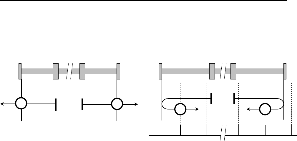
5. Operations
5-64
# Homing Method [-1] [-2]: Homing on hard stop Note)
# Homing Method [-3] [-4]: Homing on hard stop and index pulse Note)
Note) Methods [-1] to [-4] are manufacturer-specific methods.
In homing methods [-1] and [-2], the direction of homing is positive or negative respectively.
The home position shall be the mechanical end where the motor stopped.
In homing methods [-3] and [-4], the direction of homing is negative or positive respectively.
The home position shall be the first index pulse after reversing at the mechanical end where the motor stopped.
[-1] Homing on hard stop in positive direction [-3] Homing on hard stop and index pulse in negative direction
[-2] Homing on hard stop in negative direction [-4] Homing on hard stop and index pulse in positive direction
Index Pulse
-2
-1
-4-3

5.8 Operation Mode
5-65
5
O
p
erations
# Homing procedure (Ex. Homing method 7)
“Procedure for Homing method 7” is shown below:
Step 1 Preparation of homing
Set "Index 0x6098 Homing method" to "7 (0x07)".
Set "Index 0x607C Home offset".
Change "Index 0x6060 Operation mode" to "6: Homing mode".
Set "Index 0x6099-1 Home switch search speed".
Set "Index 0x6099-2 Index pulse search speed".
Set "Index 0x609A Homing acceleration".
Step 2 Homing start
Set “Index 0x6040 Control word, Bit4=1 (0x0010): Homing start”.
Step 3 Motor operation
Motor operates due to home switch/limit switch as drawing of Homing method 7.
Motor stops with negative direction index pulse.
Step 4 Confirmation of base position detection
Monitor "Index 0x6041 Status word, Bit12=1: Homing completion".
Step 5 Homing completion
Exit “Index 0x6040 Control word, Bit4 = 0 (0x0000): Homing,” and then change the control mode
back to the one using "Index 0x6060 Operation mode".
# Home position retention function when using absolute system
Execution result of homing in absolute system will be stored automatically after a homing completion.
"OD: 0x6064: Actual position” can retain the origin coordinates even when re-turning on the power next time.
In this regard, however if any encoder clear or battery errors occur, correct origin coordinate shall not be
presented, so re-homing is required. Absolute system homing “origin coordinate retention procedure” is shown
below:
Step 1 Preparation of homing
Set " Index 0x6098 Homing method" to be used.
Setting of "Index 0x607C Home offset"
Change " Index 0x6060 Operation mode" to ”6: Homing mode”.
Step 2 Homing start
Set “Index 0x6040 Control word, Bit4=1 (0x001F): Homing start”, after servo ON.
Step 3 Confirmation of reference position detection
Monitor “Index 0x6041 Status word, Bit12=1: Homing completed”.
Step 4 Setting of home offset
Calculate “OD: 0x607C Home offset” value from "OD: 0x210C Home index position", and set.
"Index 0x210C" will be update after control power cycle
Home offset (0x607C) = Origin coordinate after homing completed - Home index (0x210C)
Step 5 Storage of origin coordinate
The origin coordinates which was performed homing is stored automatically.
Do not turn off a control power
at that time.
Wait until it becomes "OD: 0x6041 Status word, Bit12=1".
Step 6 Homing completion
Exit “Index 0x6040 Control word, Bit4 = 0 (0x0000): Homing,” and then change the control mode
back to the one using " Index 0x6060 Operation mode".
✔ To update the stored origin coordinate, perform a homing of absolute system again.
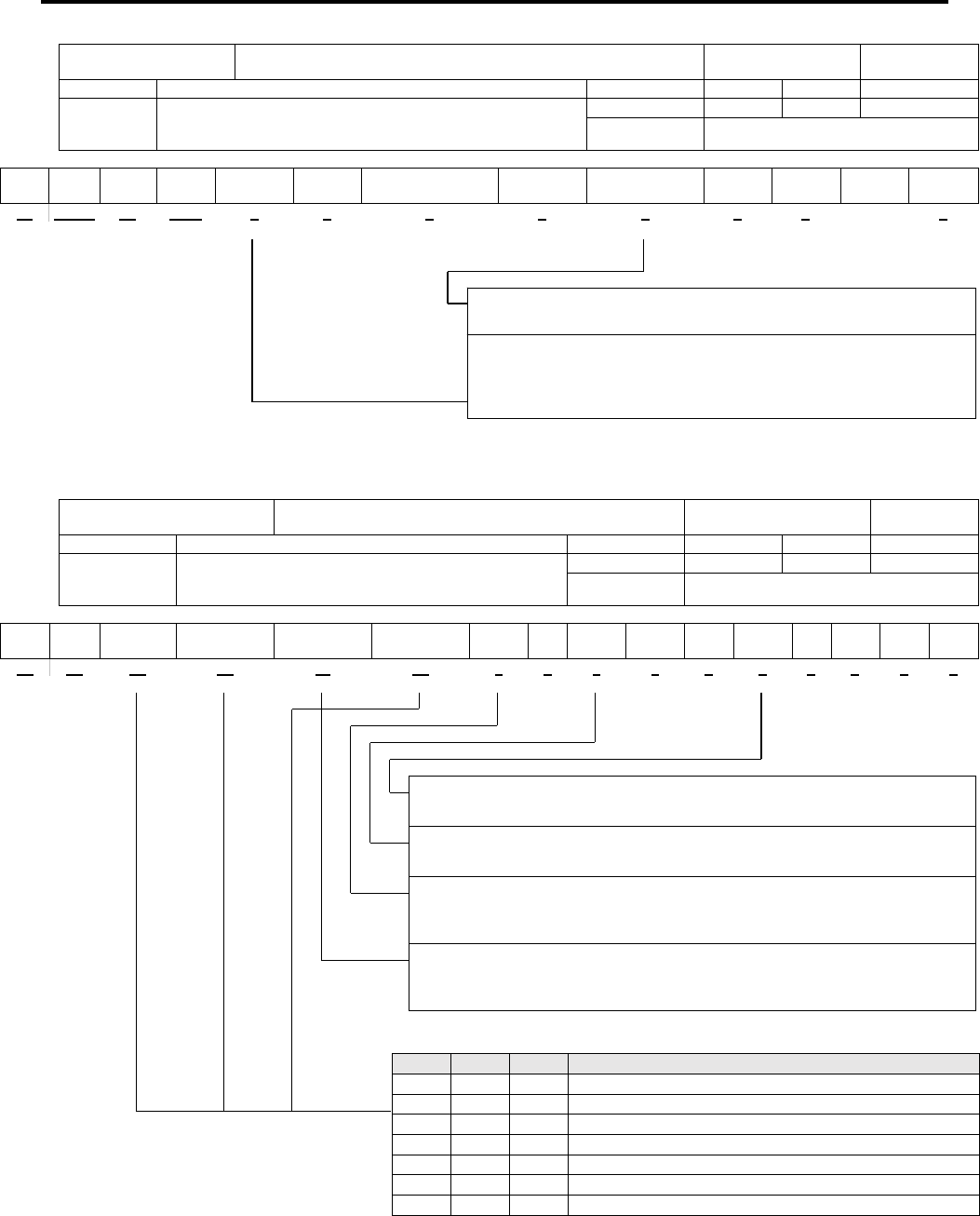
5. Operations
5-66
0x6040:Control Word (Homing Mode: hm)
Index 0x6040
This object indicates the Operation Mode Specific bit and
Manufacturer Specific bit in Homing Mode.
Object code Variable
Sub-Idx Description Data Type Access PDO Initial value
0x00 Control Word [CWORD]
*For details on Bit 7,3,2,1 and 0, see the table of Control
Word Bit Pattern Command.
Unsigned16 RW Possible 0x0000
Range 0x0000-0xFFFF
MSB LSB
Cseten - Eclr - Halt Fr*
Reserved Res
Homing
operation start
Hs*
Qs*
Ev*
So*
15 14..13 12 11..9 8 7 6 5 4 3 2 1 0
0x6041:Status Word(Homing Mode: hm)
Index 0x6041
This object indicates Operation Mode Specific bit and
Manufacturer Specific bit in Homing Mode.
Object code Variable
Sub-Idx Description Data Type Access PDO Initial value
0x00 Status Word [STSWORD]
*For details on Bit 6, 5, 3, 2, 1 and 0, see the Status Word
List Bit Pattern (Bit 6,5,3,2,1,0)
Unsigned16 RO Possible 0x0000
Range 0x0000-0xFFFF
MSB LSB
Csetfix
C
setpr
o
Homing
error
Homing
attained
Internal
Limit active
Targ et
reached
Rm Res W Sod*
Qs*
Ve F*
Oe*
So*
Rtso*
15 14 13 12 11 10 9 8 7 6 5 4 3 2 1 0
bit13 bit12 bit10 Description
0 0 0 Homing procedure is in progress
0 0 1 Homing procedure is interrupted or not started
0 1 0 Homing is attained, but target is not reached
0 1 1 Homing procedure is completed successfully
1 0 0 Homing error occurred, velocity is not 0
1 0 1 Homing error occurred, velocity is 0 (ZV)
1 1 X Reserved
bit4:Homing operation start [Homing operation start]
Start or continue homing procedure
bit8: HALT [HALT]
0:Homing function enable (Enable bit4)
1:Stop axis according to halt option code (0x605D)
bit11:Internal Limit active [Internal Limit active]
0: Nomal operation
1: While velocity limit.
bit4:Voltage Enabled [Voltage Enabled]
0:Voltage disenabled 1:Voltage enabled
bit9:remote [remote]
0: Control word is not processed
1: Being processed by control word
bit7:warning [warning]
0:No warning 1:warning condition

5.8 Operation Mode
5-67
5
O
p
erations
5.8.6 Function Group "Touch Probe"
■ Abstract of Function Group "Touch Probe" mode
“Touch Probe function” is a latching function to latch the edge-triggered encoder position by digital input.
”Touch Probe in the event” is independent from NC cycle time function since it
latches the sensor position in the hardware of the slave, therefore, it enables capture it more precisely.
This amplifier provides two of channels - Touch Prove 1 (CONT1), Touch Probe 2 (CONT2) - for inputting “Touch Probe function”.
These inputs are shared with general input so set all of selections of general input functions in 0x20F8 to except of [02: CONT1ON]
[03: CONT1OFF] [04: CONT2ON] [05: CONT2OFF] for use of "Touch Probe function".
The objects used for “Touch Probe” are indicated in the following list.
Object Lists of Touch Probe
Index Sub-Index
Name PDO Mapping
0x60B8 0x00
Touch Probe Function Possible
0x60B9 0x00
Touch Probe Status Possible
0x60BA 0x00
Touch probe pos 1 pos value (positive edge) Possible
0x60BB 0x00
Touch probe pos 1 neg value (negative edge) Possible
0x60BC 0x00
Touch probe pos 2 pos value (positive edge) Possible
0x60BD 0x00
Touch probe pos 2 neg value (negative edge) Possible
Touch prove 1 (CONT1) signal can be triggered with “touch prove 1 input or position encoder index pulse
Note 1
” by “0x60B8,
bit 2: Trigger selection.”
Touch prove 2 (CONT2) signal can be triggered with “touch prove 2 input or position encoder index pulse
Note 1
” by “0x60B8,
bit 10: Trigger selection.”
Note1) When setting trigger with position encoder index pulse, if you use incremental encoder Z-phase is used, if you
use absolute encoder, “the position that absolute data within single turn is zero” is used as index.
The sequence of Touch Probe Function is indicated as follows.
The position value latched by Touch Probe 1/2 input
The position value of positive edge latched at Touch Probe 1 (position encoder index pulse) is stored in 0x60BA.
The position value of negative edge latched at Touch Probe 1 (position encoder index pulse) is stored in 0x60BB.
The position value of positive edge latched at Touch Probe 2 (position encoder index pulse) is stored in 0x60BC.
The position value of negative edge latched at Touch Probe 2 (position encoder index pulse) is stored in 0x60BD.
The position value latched by Touch Probe function
Touch Probe 1/2
Touch Probe function
(
0x60B8
,
bit0 or 8=1
)
Touch Probe status
(
0x60B9
,
bit0 or 8=1
)
Touch Probe status
(
0x60B9,bit1 or 2=1
)
(
0x60B9,bit9or10=1
)
Touch Probe function
(
0x60B8
,
bit2 or 10=0
)
Touch Probe Position
(
0x60BA
,
0x60BB
)
(
0x60BC
,
0x60BD
)
0
Latching position
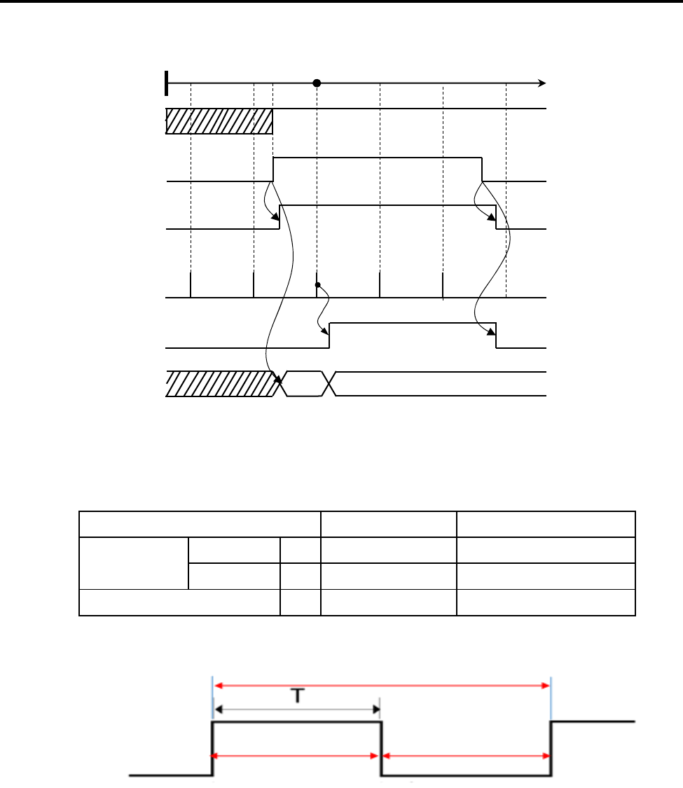
5. Operations
5-68
The position value latched by index pulse of position encoder
The position value by index pulse latched at Touch Probe 1 is stored in 0x60BA and 0x60BB.
The position value by index pulse latched at Touch Probe 2 is stored in 0x60BC and 0x60BD.
Position latching by touch probe function
■Specifications of touch probe input pulse
Limitation for touch probe input Specification Remarks
Minimum edge
interval
H pulse width
①
250 μs or more Includes turn on response.
L pulse width
②
1500 μs or more Includes turn on response.
Minimum cycle
③
1750 μs or more
Input waveform
Touch Probe Position
(
0x60BA
,
0x60BB
)
(
0x60BC
,
0x60BD
)
0
Latching position
Index Pulse
(
Zero-phase pulse,
or zero position within single turn
)
Touch Probe function
(
0x60B8
,
bit0 or 8=1
)
Touch Probe status
(
0x60B9
,
bit0 or 8=1
)
Touch Probe status
(
0x60B9,bit1or2=1
)
(
0x60B9 bit9or10=1
)
③
Minimum cycle: 1,750 μs or more
①
H pulse width
: 250 μs or more
②
L pulse width
: 1,500 μs or more

5.8 Operation Mode
5-69
5
O
p
erations
& Master-led homing (Touch probe homing method): Homing with touch-probe (without Limit Switch)
EtherCAT-support is recommended for touch probe homing to support correct and fast homing.
Toucn probe events can be accurately captured as the events function separately inside slave hardware, unlike master/ slave
sampling frequency. Examples of homing using tuch probe function are shown below:
Master-based homing using touch probe
*A) shows machine axis position, the red line shows velocity, B) shows motor position chart, and C) shows motor velocity chart.
Example of touch prove homing procesure
①
A) Machine position/
velocity
Touch probe signal
(Z
hil)
AXIS
②
③
④ ⑥⑦
⑤
B) Position
④ ⑥ ⑦
Position
⑤① ② ③
C) Velocity
Velocity
Time
Time
RS2 EtherCAT Slave (Sub) EtherCAT Master (Host)
No
Home switch reversed? (Limit switch attained)
No
Yes
Accelerate motor in reversed direction. Limit switch released?
Yes
Stop motor and reverse the rotational direction
No
0x60B8:Touch prove enabled?
Yes
0x60B8:Touch prove-enabled (bit0 = 1)
0x60FD:Digital-input monitor
No
Any events of touch prove?
Yes
④
⑤
0x60B9, bit2-1:Touch probe position stored
0x60BA, 0x60BB
:Touch probe position aquired.
Decelerate
motor
⑤
0x60B9,bit2-1: Touch probe position stored?
Yes
No
⑥
Touch probe position aquired, calculate reference and actual position.
⑦
④
Motor acceleration
③
①
②

5. Operations
5-70
5.9 SEMI F47 Support Functions
This is a function used to limit motor output current by detecting control power sag warning when
momentary power interruptions of the control power supply (drop to AC135V - AC152V) are
detected.
This is provided as a support function of “SEMI F47 Standard” required for semiconductor
manufacturing equipment.
Stoppage by alarm at the time of momentary power interruptions can be avoided and operation
can continue by combining with 0x2027: Power failure detection delay time.
1. Parameters to be set
Index Symbol Name Unit Setting range
0x20F5 CPETLSEL Torque limit selection at the time of power drop - 00 - 01
0x2072 TLMREST
Torque limit recovery value at the time of power return.
% 0.0~500.0
2. Operation sequence
Shows the sequence from the control power drop warning detection until the power return.
3. Remarks
Torque limit value at the time of control power drop warning must be less than the value in normal operation.
Torque will be limited by selected value at the time of the power drop even if the torque limit value is larger
than the value under normal operation.
Returns to torque limit value in normal operation immediately after power returns.
✔ This function is to limit torque under power failure and is not a function corresponding to all kinds
of load conditions or operational conditions.
Please make sure to use after the operation is confirmed with actual equipment.
Control Power Voltage
A
bout 150V
Voltage Drop
Warning Detection
Momentary Interruption
Bus Voltage
1ms
Torque Limit Value
Torque Limit Value selected
in CPETLSEL
Torque Limit Value selected
in TLSEL
Power Return
Returns torque limit to a value in normal time with
TLMREST % /ms after power return.
Torque limit recovery value
byTLMREST
10ms
Momentary Interruption
Control Power Voltage
Bus Voltage
Voltage Drop
Warning Detection
Torque Limit Value
Torque Limit Value selected
in TLSEL
Torque Limit Value selected
in CPETLSEL
Power Return
A
bout 150V
10ms
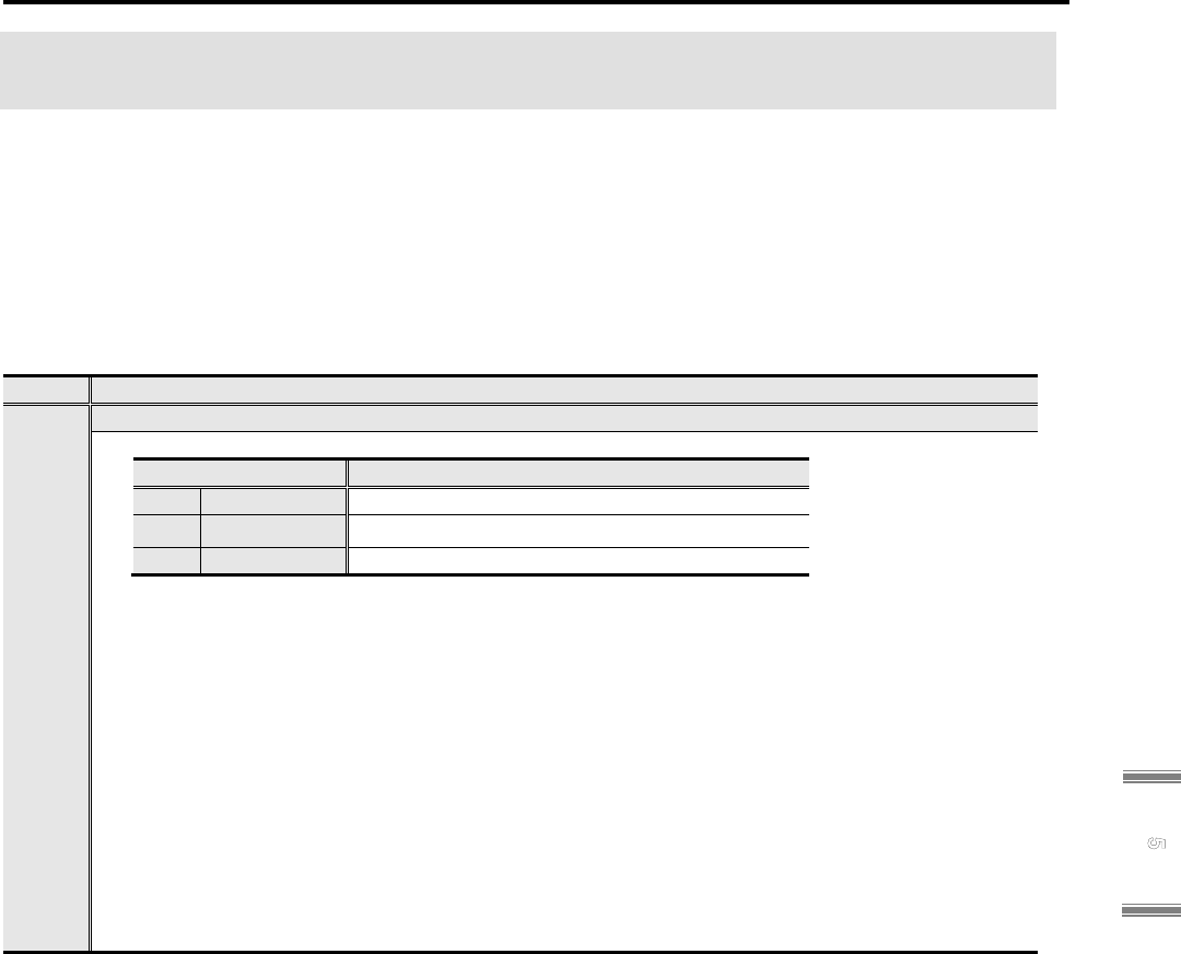
5.10 Virtual motor operation function
5-71
5
O
p
erations
5.10 Virtual motor operation function
This is the function which simulates servo motor behavior and servo amplifier status at internal of
the servo amplifier. This function is able to check a sequence with output signal and check a
wiring with upper controller, without actual motor operation. Thus, safer and faster start-up of a
system is available by this function.
As note, servo motor and encoder connection is not necessary for this function use.
5.10.1 Setting
Sets the system parameter below for this function use.
ID Contents
02
Operation mode selection
■ Selects the operation mode.
Selection Contents
00 Normal Normal operation mode
01 Virtual1 Virtual operation mode (virtual P_ON valid)
02 Virtual2 Virtual operation mode (virtual P_ON invalid)
✔ “Power cycle for control after setting”
■ Operation mode action
01:Virtual1 Virtual operation mode (virtual P_ON valid)
In this mode, servo motor operation can simulate by control power supply only.
Automatically change state to main power ON, after control power supplied.
02:Virtual2 Virtual operation mode (virtual P_ON invalid)
In this mode, servo motor operation can simulate after main circuit power supplied.
Main circuit power supply is necessary, after control power supplied.

5. Operations
5-72
5.10.2 Restrictions
There are restrictions below for this function.
■ Load model for virtual motor operation is rigid body sysytem by load inertia moment.
Item Conditions
Load torque
0 [N・m]
Load inertia moment Load inertia moment ratio × Servo motor inertia moment
Mechanical stiffness Rigid body
✔ Load inertia moment ratio is used from Group1 ID14.
The value set by the parameter below is used depending on gain switching condition if gain
switching function is used.
Selection
Used Load inertia moment ratio
Group ID Name
1 1 14 Load inertia moment ratio 1
2 4 05 Load inertia moment ratio 2
3 4 15 Load inertia moment ratio 3
4 4 25 Load inertia moment ratio 4
■ Encoder position data does not backuped. Position data is zero when power is on.
■ Multi-turn part of encoder position data does not clear even if encoder clear function is
executed.
■ Detection of alarm and warning for encoder does not work.
■ In use of pulse encoder, output pulse resolution will be 8192 [P/R] regardless of the encoder
resolution setting.
Dividing is available for this resolution by the setting of GroupC ID04 Encoder Output Pulse
Division.
■ U-phase electric angle monitor might show wrong value if pulse encoder is used.
■ Position, velocity and torque of servo motor is simulated to response of control system against
virtual motor operation load model.
■ Action of servo motor and load model is stop at servo OFF. Free-run operation at servo OFF
can not simulate.
■ When "01: Virtual" is set to Operation mode selection, main circuit power is supplied virtually,
and regard as supplying rated power. As note, Alarm and regenerative operation for main
power can not simulate.
■ Dynamic brake does not work. Stop operation by servo OFF or dynamic brake of emergency
stop can not simulate. However, the signal of While Dynamic Braking is output from general
purpose output.
■ When external encoder is serial encoder (EnDat), it works as angle encoder (resolution 28bit).

5.10 Virtual motor operation function
5-73
5
O
p
erations
5.10.3 Digital operator display
Digital operator display will change during virtual motor operation.
Display Description
Alphabet "t" shows at second LED from right, during virtual motor operation.
The other LEDs show same as normal status display.
In case except status display mode, also the same as normal.
5.10.4 Operating precautions
■ Holding-brake release signal outputs same as normal operation even if virtual motor operation
is executed. At vertical axis use, avoid holding-brake release as follows: Cancel the allocation
of holding-brake release signal for general output. Shut off the holding-brake power. etc.

5. Operations
5-74
5.11 File transferring function
In EtherCAT, servo amplifier firmware/parameter update is available using FoE mailbox protocol.
Also, it is able to upload a parameter backup value stored in amplifier with the parameter file
format of setup software.
5.11.1 Self-programing function
The function updating servo amplifier firmware from controller. Download a program file,
SANYO DENKI providing, into amplifier via controller. Amplifier updates firmware by
self-programing using downloaded program.
■ Preparation
Store a firmware file for update into controller.
Set a timeout of mailbox as below. (Our ESI file setting.)
Returning Request: 2000ms
Response: 20000ms
■ Sequence
1. Download a firmware file for update into amplifier, according to communication sequence
(in the section 5.3.4).
2. Firmware rewriting starts after download completion with ESM transition to INIT from
BOOT.
3. "LOAD" is indicated to the digital operator display while rewriting firmware.
4. "END" is indicated after rewriting completion, then servo amplifier restarts.
■ Restrictions and precautions
✔ Do not shutdown a control power while rewriting firmware. It may cause of program update
failure.
✔ EtherCAT communication is not available while rewriting firmware. (Link shutdown)
✔ Perform control power cycle after firmware rewriting completion. It may not be able to start
operation soon due to safety module or combined encoder.
✔ Add extension (.hex or .efw), for acknowledge. Filename is up to 25 characters including
extension.
✔ Contact us for password at downloading.
✔ Data processing time in amplifier is required, so keep communication cycle of FoE mailbox
communication 15 to 20ms. (Downloading time depends on communication cycle with upper
device.)
✔ Firmware rewriting requires 1 minute around.

5.11 File transferring function
5-75
5
O
p
erations
5.11.2 Parameter download function
The function updating servo amplifier parameter from controller. Download a parameter file,
generated by setup software (ap1) or amplifier, into amplifier via controller, and set a parameter
of servo amplifier.
■ Preparation
Store a parameter file for setting into controller.
■ Sequence
1. Download a parameter file for setting into amplifier, according to communication sequence
(in the section 5.3.4).
2. Performs matching check after download completion, and save a downloaded parameter if
there is no problem.
3. "Parameter update completion" alarm is issued after parameter saving. Turn control power
off and on again to restart a servo amplifier.
■ Restrictions and precautions
✔ Do not shutdown a control power while saving parameter. It may cause of parameter setting
failure.
✔ Perform download function again when a control power was shut off while saving parameter.
✔ Mailbox size shall be set to 512byte for use.
✔ Axis name of amplifier parameter file is up to 64 characters. (1 character with 2 byte)
✔ This function updates all parameter area. (System/Motor/General parameters)
✔ Add extension (.ap1), for acknowledge. Filename is up to 25 characters including extension.
✔ Password input is not required at downloading.

5. Operations
5-76
5.11.3 Parameter upload function
The function reading out the parameter set value stored in amplifier, with the parameter file
format of setup software. Readout parameter can check or edit by the setup software. Also,
readout parameter can download to another amplifier.
■ Preparation
Generate an upload file by performing EtherCAT object, parameter save (0x1010).
■ Sequence
1. Get a stored file size, from the object: Backup file information (0x2138).
2. Set "0x00: AP1 file" to FoE Uploading File Selection (0x207B).
3. Upload a parameter file for setting into amplifier, according to communication sequence (in
the section 5.3.4).
4. Confirm match with file size in the backup file information and a data size calculation of the
file received via controller.
■ Restrictions and precautions
✔ Parameter file to be uploaded is the parameters when parameter save (0x1010) is performed.
It is required that performing parameter save (0x1010) again if parameter is changed.
✔ Generated file size will be 220 kbytes around.
✔ Generated file is simplified format so it does not cover all functions in the setup software.
5.11.4 Drive recorder data upload function
The function reading out the drive recorder data stored in amplifier with the file format
displayable in the setup software. Readout drive recorder data file can view with the setup
software.
■ Preparation
Set desired monitor data/trigger to EtherCAT object, drive recorder parameter (0x2070), and
get a drive recorder data by issuing trigger condition.
■ Sequence
1. Set "0x01: Drive recorder file" to FoE Uploading File Selection (0x207B).
2. Upload a parameter file for setting into amplifier, according to communication sequence (in
the section 5.3.4).
3. Confirm match with file size in the drive recorder data in 0x2139-0x02 and a data size
calculation of the file received via controller.
■ Restrictions and precautions
✔ Drive recorder data file to be uploaded has data due to 16 times trigger condition. To clear a
drive recorder, perform the object: Drive recorder clear (0x2073).
✔ Generated file size will be 193 kbytes around.
✔ Refer separate manual M0010842 for detail of drive recorder.

5.11 File transferring function
5-77
5
O
p
erations
5.11.5 System analysis data upload function
The function performing system analysis through communication (just performed in the setup
software, in the past) and reading out the drive recorder data stored in amplifier with the file
format displayable in the setup software. Readout system analysis data file can view with the
setup software.
■ Preparation
Generate a system analysis file by performing EtherCAT object, System analysis data
measurement (0x2054).
■ Sequence
1. Get a stored file size, from the object: System analysis file size (0x2139-0x03).
2. Set "0x02: System analysis file" to FoE Uploading File Selection (0x207B).
3. Upload a data file for setting into amplifier, according to communication sequence (in the
section 5.3.4).
4. Confirm match with file size in the drive recorder data in 0x2139-0x03 and a data size
calculation of the file received via controller.
■ Restrictions and precautions
✔ System analysis data file to be uploaded has parameters at the time performing a system
analysis data measurement (0x2054). Data will be overwrite if drive recoder or trace function
is performed so perform data upload soon after running a system analysis data measurement
(0x2054).
✔ Generated file size will be 13 kbytes around.
Read separate manual M0010842 for detail of system analysis.

5. Operations
5-78
5.12 High speed sampling mode
It becomes that communication cycle 62.5 μs is able to use if control cycle is set as high speed
sampling mode.
5.12.1 Setting
For use of this function, system parameter below shall be set.
ID Description
00
Control cycle
■ Selects a control cycle of velocity control or torque (force) control.
Selection Description
00 Standard_Sampling Standard sampling mode
01 High-freq_Sampling High speed sampling mode
✔ Perform control power cycle after setting.
5.12.2 Dedicated function in high speed sampling mode
62.5 μs of communication cycle becomes available when high speed sampling mode is
selected.
■ Applicable communication cycle is 62.5 μs only.
■ Object number allowing PDO mapping is 10 maximum.
■ Operation mode applies cyclic sync velocity mode (CSV) or cyclic sync torque (force) mode
(CST) only.
■ The objects updating with 62.5 μs communication cycle are listed below.
The other objects are update with 125 μs even if PDO mapping is performed.
List of objects updating with 62.5 μs communication cycle
Index S-Idx Name Data Type Unit
0x60FF 0x00 Target velocity Integer32 Pulse/s
0x6071 0x00 Target torque (force) Integer16 0.1 %
0x6064 0x00 Actual position Integer32 Pulse
0x606C 0x00 Actual velocity Integer32 Pulse/s
0x6077 0x00 Actual torque (force) value Integer16 0.1 %

5.12 High speed sampling mode
5-79
5
O
p
erations
5.12.3 Restrictions
There are restrictions for functions below, when high speed sampling mode is selected.
■ This function is not able to use with servo amplifier with functional safety module.
■ This function is not able to use with position control.
■ Parameters of restricted functions shall be selected as below.
Parameter set values of restricted functions
Disabled function Index Group ID Name Set value
Model following
(vibration
suppression)
control
0x20F3-0x01 System 07 Position control selection 0x00 : Standard
Full-closed control 0x20F3-0x02 System 20 Position loop control
encoder selection
0x00 : Motor_Enc
Scale 0x6091-0x01 System 43 Motor shaft resolution 1
0x6091-0x02 System 44 Drive shaft resolution 1
0x6092-0x01 System 45 Feed
(Travel Distance)
1

5. Operations
5-80
5.13 Scale function
For use of scale function, it shall be decided a scale coefficient of unit conversion.
Scale coefficient is set by a scale related parameter in system parameter.
(→ 5.13.1 Scale setting)
After scale coefficient decision, set a parameter value set by this unit.
(→ 5.13.2 Parameters affected by scale setting)
5.13.1 Scale setting
For use of this function, parameter below shall be set.
Index Sub-index Name Description
0x60A8 0x00 SI unit system for
position
Sets a unit of position system.
In this amplifier, fixed to zero.
0x6091 0x01 Motor Shaft Resolution Sets the rotation speed of motor axis.
0x6091 0x02 Drive Shaft Resolution Sets the rotation speed of output axis.
0x6092 0x01 Feed (Travel Distance) Sets the travel distance in one rotation of the motor axis.
- - Position loop encoder
resolution
Indicates a pulse number per rotation in encoder for
position loop.
This is calculated by the value set at 0x20FF-0x01.
In use of incremental encoder:
It becomes 4-multiplied value of selected resolution.
In use of absolute encoder:
It becomes a value of selected FMT.

5.13 Scale function
5-81
5
O
p
erations
5.13.2 Parameters affected by scale setting
Index Sub-index Name
0x6065 0x00 Position Deviation Window (Position Deviation Counter Overflow Value)
0x6067 0x00 Position Window (Positioning completion range)
0x607A 0x00 Target Position
0x607B 0x01
0x02
Position range limit minimum value
Position range limit maximum value
0x607C 0x00 Home offset
0x607D 0x01
0x02
Software position limit minimum value
Software position limit maximum value
0x607F 0x00 Maximum Profile Velocity
0x6081 0x00 Profile Velocity
0x6083 0x00 Profile Acceleration
0x6084 0x00 Profile Deceleration
0x6085 0x00 Quick Stop Deceleration
0x6099 0x01 Home Switch Searching Velocity
0x6099 0x02 Zero Phase Searching Velocity
0x609A 0x00 Homing acceleration and deceleration
0x60B0 0x00 Position Offset
0x60B1 0x00 Velocity Offset (Velocity Compensation Value)
0x60C1 0x01 Interpolation position command value
0x60C5 0x00 Maximum acceleration
0x60C6 0x00 Maximum deceleration
0x60FF 0x00 Target Velocity
0x203C 0x00 Software Limit Deceleration
0x5083 0x01 to n Correction Position 1 to Correction Position n
0x5084 0x01 to n Offset 1 to Offset n
0x5091 0x00 Backlash Correction Value
0x20F6 0x04 Position Deviation Excess Value for Hard Stop

5. Operations
5-82
5.13.3 Monitors affected by scale setting
Index Sub-index Name
0x6062 0x00 Position Demand Value
0x6064 0x00 Actual Position
0x6069 0x00 Actual Velocity Sensor Value
0x606C 0x00 Actual Velocity Value
0x60F4 0x00 Actual Position Deviation
0x2110 0x01 to 0x07 Control Cycle Actual Position
0x2111 0x01 to 0x07 Control Cycle Actual Velocity
0x2116 0x00 Actual Velocity Value 2
0x2117 0x00 Actual Position Value 2
5.13.4 Scale conversion coefficient
Scale conversion coefficient is calculated with equation below.
(1) Scale conversion command coefficient
It is used to a command or parameter provided by upper device.
Scale conversion command coefficient =
(2) Scale conversion monitor coefficient
It is used to a monitor value responded with amplifier.
Scale conversion monitor coefficient =
5.13.5 Restrictions
There are restrictions below for scale function.
■ It is not able to use with communication cycle 62.5 μs or 125 μs.
■ It is not able to use with touch probe function.
Motor shaft resolution x Position loop encoder resolution
Drive shaft resolution x Feed
Drive shaft resolution x Feed
Motor shaft resolution x Position loop encoder resolution

5.14 Extended function selection
5-83
5
O
p
erations
5.14 Extended function selection
SANMOTION R 3E Model EtherCAT servo amplifier has Extended function selection.
5.14.1 Deceleration stop function with velocity control mode in
torque control mode
Index Sub-Index Description
0x2079 0x01 Sets valid/invalid of deceleration stop special function in torque
control mode.
0x01 (Function valid), 0x00 (Function invalid)
Deceleration stop method in quick stop will be changed if function is
valid.
0x2079 0x02 Selects stop condition at communication alarm when deceleration
stop special function in torque control mode is valid.
0x01 (Function valid): Stops after switching in to velocity mode.
0x00 (Function invalid): Stop condition will be according to abort
option code.
5.14.2 Function abstract
Functions below are worked when torque profile mode or cyclic sync torque mode is selected
with operation mode (0x6060) and function valid is selected with extended function selection
(0x2079-0x01).
(1) Condition performing deceleration stop after switching in to velocity mode from torque mode
Condition Description Remarks
Communication
cause
Performs deceleration stop if quick stop is
input via communication.
(Quick stop is decided if bit2 of control word is
zero.)
It stops with setting of profile deceleration
regardless of another setting of option code for
deceleration stop, when this function is
selected.
Deceleration stop is performed due to
communication cause if special function
selection (0x2079-0x02) is valid.
Amplifier cause Performs deceleration stop when servo
amplifier detects cause of emergency stop
(EMR).
Deceleration stop method differs due to cause.
Refer ① to ④ below.
① In case that EMR is assigned to general
input and EMR request is occurred.
② In case that main circuit is shut down.
(Power off)
This function does not work because gate will
be shut down by hardware.
③ Emergency stop (EMR) due to STO input.
④ Alarm cause
Depends on operation of alarm detection.
In case of SB (servo brake stop):
Deceleration stop is performed with this
function.
In case of DB (dynamic brake stop):
This function does not work.
It will be stop operation with dynamic brake.
(2) Operation if deceleration stop condition occurred
If deceleration stop condition occurred, actual operation motor speed will be decided to
velocity command.
Based on that speed, deceleration stop is started with set profile deceleration.

5. Operations
5-84
5.14.3 Deceleration stop special function in position control mode
Index Sub-Index Description
0x2079 0x03 Selects valid/invalid of deceleration stop special function in position
control mode.
0x01 (Function valid): Changes to velocity mode and performs
deceleration stop.
0x00 (Function invalid): Function invalid
5.14.4 Function abstract
Functions below are worked as deceleration stop special function when cyclic sync position
mode is selected with operation mode (0x6060), function valid is selected with extended function
selection (0x2079-0x03), and 0x0005 or 0x0006 is selected with quick stop option code
(0x605A).
(1) Condition performing deceleration stop after switching in to velocity mode from position
control mode.
Condition Description Remarks
Communication
cause
Performs deceleration stop if quick stop is input
via communication.
(Quick stop is decided if bit2 of control word is
zero.)
It stops with profile deceleration, when this
function is selected and 5 is selected with quick
stop option code (0x605A). It stops with quick
stop deceleration when 6 is selected.
This function doesn't work with the other
selections. (Normal function will be used.)
Even if this function is selected, it performes deceleration stop due to amplifier cause when servo off (gate shut off)
occurs with amplifier cause below.
Servo off (gate shut off) occurs so it cannot keep staying at quick stop active state.
Amplifier cause Performs deceleration stop when servo amplifier
detects cause of servo off (gate shut off).
Even if this function is selected, it performes
deceleration stop due to amplifier cause.
① In case that EMR is assigned to general
input and EMR request is occurred.
② In case that main circuit is shut down.
(Power off)
This function does not work because gate will
be shut down by hardware.
③ Emergency stop (EMR) due to STO input.
④ Alarm cause
Depends on operation of alarm detection.
In case of SB (servo brake stop):
Deceleration stop is performed with this
function.
In case of DB (dynamic brake stop):
This function does not work.
It will be stop operation with dynamic brake.
(2) Operation if deceleration stop condition occurred
If deceleration stop condition occurred, actual operation motor speed will be decided to
velocity command.
Based on that speed, deceleration stop is started with set profile deceleration.

5.14 Extended function selection
5-85
5
O
p
erations
(3) Working example
Below shows a working example: Performs quick stop by setting 0x000B to control word and
performs servo off by 0x0000, then servo on.
(Control word is just shown bit 3 to bit 0. )
① Set 1011 (Quick stop) to bit 3- 0 of control word.
② Confirm completion of deceleration stop.
③ Set 0110 (Shut down) to bit 3- 0 of control word.
④ Set 0111 (Swich On) to bit 3- 0 of control word.
⑤ Set 1111 (Enable operation) to bit 3- 0 of control word.
Time (ms)
Velocity (min
-1
)
n (min
-1
)
0 (min
-1
)
Control mode
Control word
(bit3: EnableOperation)
(bit2: QuickStop)
③
②
①
④
⑤
Position control
Velocity control
Position control

5. Operations
5-86
5.14.5 Restrictions
There are restrictions below for extended function selection.
■ If gate has shut down by another cause such as alarm, it is not able to stop with set
deceleration speed.
■ In case that deceleration stop has selected at quick stop option code, it may not perform
deceleration stop correct if quick stop state cancels before starting deceleration stop. To stop
motor with deceleration stop, keep a quick stop state until motor stop.
■ The term of switched to velocity control mode is up to 1 second. Deceleration stop time in
profile deceleration setting shall be set to 1 second or less.
■ In case after deceleration stop using special function selection in position control, it has gap
on a command coordinate against upper device (controller), with keeping servo on state. Do
not cancel a quick stop input at this state.

5.15 Modulo function
5-87
5
O
p
erations
5.15 Modulo function
5.15.1 Modulo setting
Sets the system parameter below for this function use.
Index Sub-index Name Description
0x607B 0x01 Position range limit
minimum value
Sets minimum value as available in position coordinate,
under operation mode of position command input system.
0x607B 0x02 Position range limit
maximum value
Sets maximum value as available in position coordinate,
under operation mode of position command input system.
0x60F2 0x00 Positioning option
code
Set a behavior of positioning operation.
5.15.2 Function abstract
(1) 0x607B: Position range limit
Sets range in position coordinate, under operation mode of position command input system.
0x607B
Position range limit
Graphical image Description
Min. = 0x00000000
Max. = 0x00000000
Linear coordinate
(Linear axis)
- In case PP, wraparound is available
beyond the range of position range limit
when position range limits are set as
below.
Min. (0x607B-0x01) =0x00000000
Max. (0x607B-0x02) =0x00000000
Min. = 0x80000000
Max. = 0x7FFFFFFF
Linear coordinate
(Linear axis)
- In case PP, the command beyond the
range of position range limit becomes
invalid and travel disabled, when position
range limits are set as below.
Min. (0x607B-0x01)=0x80000000
Max. (0x607B-0x02)=0x7FFFFFFF
- In case CSP, wraparound is available.
Except settings above
Modulo coordinate
(Rotary axis)
- In case coordinate increment direction,
next position after reaching maximum of
position range is minimum of position
range.
- In case coordinate decrement direction,
next position after reaching minimum of
position range is maximum of position
range.
Positionren gelimitMIN=0x80000000
Positionren gelimitMAX = 0x7 FFFFFFF
初期位置
到達位置
Position range limit MAX. = 0x7FFFFFFF
Position range limit MIN. = 0x80000000
Initial
position
Attainment
position
Positionren ge limitMIN=0x80000000
Positionren ge limitMAX= 0x7FFFFFFF
ラ ップアラウンドする指令は無効
Position range limit MAX. = 0x7FFFFFFF
Position range limit MIN. = 0x80000000
Command with
wraparound is invalid
Positionren gelimitMAX
Positionren gelimitMIN
Position range limit MIN.
Position range limit MAX.

5. Operations
5-88
(2) 0x60F2: Positioning option code
In case that target position is set with absolute position command, it travels depending on
positioning option code.
Below shows modulo coordinate images with conditions: minimum position range limit = 0,
maximum position range limit = 359.
Positioning
option code
Modulo coordinate
Image with rotary
axis
Modulo coordinate
Graphical image
Description
Bit6 Bit7
0 0
- Performs positioning of travel
to the direction that modulo
coordinate does not
wraparound.
0 1
- Performs positioning of travel
to the direction of coordinate
decrement.
- Even if target position is larger
than actual position,
positioning is performed to
target position go through the
position set by minimum
position range limit.
1 0
- Performs positioning of travel
to the direction of coordinate
increment.
- Even if target position is
smaller than actual position,
positioning is performed to
target position go through the
position set by maximum
position range limit.
1 1
- Automatically decide shortcut
direction, and travel.
- When target position and
actual position are just
opposite, rotation direction is
decided to positive.
Normal positioning
same as linear axis
Shortcut direction
rotation
Negative direction
rotation only
Positive direction
rotation only
50
0
210
150
330
360
Positionrengelimit MAX
Positionrengelimit MIN
Position range limit MIN.
Position range limit MAX.
50
0
210
150
330
360
Positionrengelimit MAX
Positionreng elimitMIN
Position range limit MIN.
Position range limit MAX.
50
0
210
150
330
360
Positionrengelimit MAX
Positionreng elimitMIN
Position range limit MIN.
Position range limit MAX.
50
0
210
150
330
360
PositionrengelimitMAX
Positionrengelimit MIN
初期位置
到達位置
Position range limit MIN.
Position range limit MAX.
Initial position
Attainment
position

5.15 Modulo function
5-89
5
O
p
erations
■ Sequence
1. Set position range limit minimum value (0x607B-0x01) and position range limit maximum
value (0x607B-0x02). To change setting, transit ESM state to Pre-Operational and change
setting, then transit to Operational again.
2. Confirm with monitor value of actual position that position range limit minimum value
(0x607B-0x01) and position range limit maximum value (0x607B-0x02) are reflected and
actual position is not there in out of range.
3. Set a positioning operation with bit6 and bit 7 of positioning option code (0x607B-0x00).
Positioning option code becomes valid soon after inputting.
■ Restrictions and precautions
✔ CSP mode is not apply to positioning option code. It travels to modulo position by position
command, with shortcut direction rotation.
✔ In case that positioning option code is normal positioning same as linear axis and target
position is set to out of modulo coordinate, modulo is performed to target position. For example
in case position range limit minimum value is 0 and position range limit maximum value is 359,
absolute position command 370 gets modulo and travel to 10, without wraparound.

5. Operations
5-90
5.16 Protective function
5.16.1 Position deviation difference excess warning/alarm
■ Abstract
Position deviation difference excess warning/alarm detects position deviation error
accurately in position control mode.
It detects warning or alarm when absolute value of position deviation difference
between counter and velocity feedback calculation becomes too large.
■ How to use
To use this function, all settings below are required. If some settings are not set,
position deviation difference warning level and excess value are required to set to zero.
(Detection invalid)
✔ Set "01: PP" or "08: CSP" to 0x6060 Operation mode.
✔ Set "00: Standard control" to 0x20F3-0x01 Position control selection.
Set servo amplifier parameters correct, and check maximum value of position deviation
difference in normal operation.
✔ Position deviation difference is able to check with 0x2131 Position deviation difference
monitor.
✔ In case that position deviation difference becomes too large during motor accel/decel,
position deviation difference is able to suppress with adjustment of Position Deviation
Difference Excess Detection LPF.
In case that position deviation difference becomes large temporarily, set the time longer
than it to Position Deviation Difference Detection Continuing Time.
Position deviation difference warning level and excess value are required to set as
larger than position deviation difference monitor value with margin.
Position deviation difference excess warning/alarm occurs when position deviation
difference exceeds warning level or excess value.
Position command
input operation
Position
deviation
counter
KP
Velocity
control
Torque
control
Position deviation
difference detecting
low-pass filter
PDDLPF
Servo motor
Motor encoder
Position deviation
+
-
Velocity
detection
1/KP
Position deviation difference
Position deviation
(Back-calculation from velocity feedback)
+
-
Velocity feedback

5.16 Protective function
5-91
5
O
p
erations
■ Setting parameters
To use position deviation difference excess warning/alarm, setting of parameters below
are required.
Position deviation difference excess warning level
Position deviation difference excess warning occurs if position deviation difference
exceeds this value and spending Position Deviation Difference Detection Continuing
Time (0x2052-0x04).
Index SubIndex Setting range Initial value Unit
0x2052 0x01 0 to 2147483647 0
Pulse
✔ Position deviation difference warning is not detected when set value is 0.
✔ Warning status is able to check via monitor display and front LED.
Moreover, that is able to output via general output.
Position deviation difference excess value
Position deviation difference excess alarm "AL.D8" occurs if position deviation
difference exceeds this value and spending Position Deviation Difference Detection
Continuing Time (0x2052-0x04).
Index SubIndex Setting range Initial value Unit
0x2052 0x02 0 to 2147483647 0
Pulse
✔ Position deviation difference warning is not detected when set value is 0.
Position deviation difference excess detection low-pass filter
The set value for adjusting LPF of position deviation difference excess alarm/warning
detection.
Index SubIndex Setting range Initial value Unit
0x2052 0x03 0 to 4000 0
Hz
✔ The filter is disabled by setting value 0Hz, or 2000Hz or more.
Position deviation difference detection continuing time
Alarm or Warning issues when position deviation difference excess level or warning
level continues with this setting time.
Index SubIndex Setting range Initial value Unit
0x2052 0x04 0 to 1000 0
ms
■ Precautions
We cannot assure the perfect prevention by this function against machine break-down.

5. Operations
5-92
5.17 Correction table function
This is the function to correct pitch error of ball screw.
5.17.1 Related parameters
For use of this function, parameter below shall be set.
Index Sub-index Name Description
0x5080 0x00 Correction Table Control Enables/disables the correction table function.
0x5083 0x00 Correction Table Position
Number of entry
Sets number of entry of correction position.
0x5083 0x01 to n Correction Position 1 to n Sets correction position.
0x5084 0x00 Correction Table Offset
Number of entry
Sets number of entry of offset.
0x5084 0x01 to n Offset 1 to n Sets offset.
5.17.2 How to set a correction able
①Sets correction data number to 0x5083 sub-idx 0x00 and 0x5084 sub-idx 0x00.
Maximum correction data number is 64.
②Sets correction position to sub-idx 0x01 or later in 0x5083.
Correction position shall be set in order from small number. Set value will be stored to non-volatile
memory.
③Sets offset to sub-idx 0x01 or later in 0x5084.
Set value will be stored to non-volatile memory.
④After setting correction position and offset, perform control power cycle.
■In cases below, warning for correction table setting will be set. Review set values.
◆In case that 1 is set to number of entry.
◆In case that correction position is not set with order from small number.

5.17 Correction table function
5-93
5
O
p
erations
5.17.3 Correction table operation
Correction table function works as below.
①Refers correction table with actual position.
②If Actual position is inside of correction table, neighbor 2 correction positions are referenced.
(See Ex. 1)
If Actual position is outside of correction table, 2 correction positions near to table reference data are
referenced. (See ex. 2)
③Calculates correction value with linear interpolation of offset values due to correction positions
decided above.
(Ex. 1) Actual position is inside of correction table
(Correction position 1 ≤ Actual position < Correction position n)
(Ex. 2) Actual position is outside of correction table
(Actual position < Correction position 1, or Correction position n ≤ Actual position)
Offset
Correction
position
Actual
position
Correction
value
Correction
position 1
Correction
position 2
Correction
position 3
Correction
position n-1
Correction
position n
Offset
Correction
position
Correction
value
Correction
position 1
Correction
position 2
Correction
position 3
Correction
p
osition n-1
Correction
position n
Actual
position

5. Operations
5-94
5.17.4 Precautions
①Clearance of position data, set to correction position (Index 0x5083 sub-idx 0x01-), is required to be
larger than travel distance in 125μs.
②In case that actual position steps over 0x7FFFFFFF and 0x80000000, set 0x80000000 to correction
position 1 and set 0x7FFFFFFF to correction position n. Set same value to offset 1 and offset n. (n:
number of entry)
③Set correction positions and offsets so as to slope of the line between 2 correction points is 0.1 or
less.
Large slope may cause of vibration.
Slope = Offset differential value / Correction position differential value
Position
Offset
0x80000000 0x7FFFFFFF
Correction position 1
Correction position n
Offset
Position
Minimum clearance of correction position
Offset
Position
Offset differential value
Correction position differential value

5.18 Special function selection setting
5-95
5
O
p
erations
5.18 Special function selection setting
Explains about functions requiring a special function selection setting.
5.18.1 How to use of gain switching function
Gain switching function setting differs due to bit 9 of special function selection setting.
Index Set value Description
0x20F7
Bit9
0 Sets a gain by gain switching selection (bit 4-5) of parameter
selection (0x2001).
1 Sets a gain by gain switching condition (0x20B0).
5.18.2 How to use of velocity loop proportional control switching
function
Velocity loop proportional control switching function setting differs due to bit 10 of special function
selection setting.
Index Set value Description
0x20F7
Bit10
0 Sets by bit 2 of function control word (0x2000).
1 Sets a velocity loop proportional control by Velocity Loop
Proportional Control Switching Condition (0x20F8-8).

5. Operations
5-96
5.19 Restrictions
SANMOTION R 3E Model EtherCAT servo amplifier has restrictions below.
5.19.1 Restriction list
Item Restriction condition
Profile Position mode According to communication specification, inhibit "1" set to New Setpoint
when "0" is set to profile velocity/profile acceleration/profile deceleration.
Profile Position mode
(Halt stop)
To restart after canceling halt stop, set profile velocity/profile
acceleration/profile deceleration and set "1" to New Setpoint.
Software Position Limit In case that software position limit valid, profile position mode works as
below.
If a target beyond software position limit is set, it does not move due to
Internal Limit Active (bit 11 of 0x6041: Status Word).
Alarm Reset
(Fault reset)
Set "1" 20ms or more to Fault Reset (bit7 of Control Word), to clear an
alarm cause of amplifier internal.
Alarm state will be canceled with negative edge of Fault Reset (bit7 of
Control Word).
Encoder clear
(Eclr)
Set "1" 200ms or more to Eclr (bit12 of Control Word), to clear battery
error or multi-turn data of motor encoder internal. Actual position
recalculation after multi-turn data clear will be performed with negative
edge of Eclr (bit12 of Control Word).
Control cycle actual position
Control cycle actual velocity
Control cycle actual torque
Control cycle of monitor process will be 250μs if scale function is used.
So, monitor value update of actual position/actual velocity/actual torque,
outputting every control cycle, is also every 250μs.
SI unit system for position This parameter defines scale unit, only. Decide scale unit with reference
of section 5.13.4.
EtherCAT communication
reception monitor
EtherCAT communication reception timing monitor becomes valid when
DC sync mode is selected, only.
Measure range from sync signal (negative edge of SYNC) to
communication frame reception (negative edge of IRQ) is up to
communication cycle. Maximum measure value is communication cycle.
Measure range of communication cycle from communication frame
reception (negative edge of IRQ) to communication frame reception
(negative edge of IRQ) is up to twice of communication cycle.
Measurement is performed under Operational status of EtherCAT State
Machine (ESM).
Measured value clears once if transit from Operational state.
Home Switch CONT1 (HomeSwitch) is assigned to home switch as dedicated input
automatically.
This input is shared with general input so general input function
selection (0x20F8) shall be set avoid "02:CONT1ON" and
"03:CONT1OFF", when home switch input is used.

Release
Revision A Sep. 2017
Revision B Oct. 2018
Revision C May. 2019

* For any question or inquiry regarding the above, contact our Sales Department.
https://www.sanyodenki.com
SANYO DENKI CO., LTD.
TEL: +81 3 5927 1020
3-33-1 Minami-Otsuka, Toshima-ku, Tokyo 170-8451, Japan
SANYO DENKI EUROPE SA. TEL: +33 1 48 63 26 61
P.A. Paris Nord Ⅱ, 48 Allée des Erables-VILLEPINTE, BP.57286, F-95958 ROISSY CDG Cedex, France
SANYO DENKI AMERICA, INC. TEL: +1 310 783 5400
468 Amapola Avenue Torrance, CA 90501, U.S.A.
SANYO DENKI SHANGHAI CO., LTD. TEL: +86 21 6235 1107
Room 2106-2110, Bldg A, Far East International Plaza, No.319, Xianxia Road, Shanghai, 200051, China
Beijing Branch TEL: +86 10 6522 2160
Room1222, Tower B, Beijing COFCO Plaza, No.8 Jianguomennei Dajie, Dong Cheng District, Beijing 100005 China
SANYO DENKI (H.K.) CO., LIMITED TEL: +852 2312 6250
Room 2305, 23/F, South Tower, Concordia Plaza, 1 Science Museum Rd., TST East, Kowloon, Hong Kong
SANYO DENKI TAIWAN CO., LTD. TEL: +886 2 2511 3938
N-711, 7F, Chia Hsin 2nd Bldg., No.96, Sec.2, Zhongshan N. Rd., Taipei 10449, Taiwan (R.O.C.)
SANYO DENKI SINGAPORE PTE.LTD. TEL: +65 6223 1071
988 Toa Payoh North, #04-08, Singapore 319002
Indonesia Representative Office TEL: + 62 21 252 3202
Summitmas II 4th Floor, Jl. Jend. Sudirman Kav.61-62, Jakarta 12190, Indonesia
SANYO DENKI GERMANY GmbH TEL: +49 6196 76113 0
Frankfurter Strasse 80-82, 65760 Eschborn, Germany
SANYO DENKI KOREA CO., LTD. TEL: +82 2 773 5623
15F, KDB Building, 372, Hangang-daero, Yongsan-gu, Seoul, 04323, Korea
Busan Branch TEL: +82 51 796 5151
8F, CJ Korea Express Bldg., 119, Daegyo-ro, Jung-gu, Busan, 48943, Korea
SANYO DENKI (Shenzhen) CO., LTD. TEL: +86 755 3337 3868
2F 02-11, Shenzhen International Chamber of Commerce Tower, No.168 Fuhua 3 Road, Futian District, Shenzhen, 518048 China
Tianjin Branch TEL: +86 22 2320 1186
Room AB 16th Floor TEDA Building, No. 256 Jie Fang Nan Road, Hexi District, Tianjin 300042 China
Chengdu Branch TEL: +86 28 8661 6901
Room2105B, Block A, Times Plaza, 2 Zongfu Road, Jinjiang District, Chengdu, 610016 China
SANYO DENKI (THAILAND) CO., LTD. TEL: +66 2261 8670
388 Exchange Tower, 25th Floor, Unit 2501-1, Sukhumvit Road, Klongtoey, Klongtoey, Bangkok 10110 Thailand
SANYO DENKI INDIA PRIVATE LIMITED TEL: +91 44 420 384 72
#14 (Old No.6/3), Avenue Road, Nungambakkam, Chennai - 600034, Tamil Nadu, India
The names of companies and/or their products specified in this manual are the trade names, and/or trademarks and/or registered trademarks of such respective companies.
*Specifications are subject to change without notice.
Translated version of the original instructions
■ Precautions For Adoption
Failure to follow the precautions on the right may
cause moderate injury and property damage, or in
some circumstances, could lead to a serious
accident.
Always follow all listed precautions.
Cautions
Read the accompanying Instruction Manual carefully prior to using the product.
If applying to medical devices and other equipment affecting people’s lives please contact us beforehand
and take appropriate safety measures.
If applying to equipment that can have significant effects on society and the general public, please contact
us beforehand.
Do not use this product in an environment where vibration is present, such as in a moving vehicle or
shipping vessel.
Do not perform any retrofitting, re-engineering, or modification to this equipment.
The Products presented in this Instruction Manual are meant to be used for general industrial
applications. If using for special applications related to aviation and space, nuclear power, electric power,
submarine repeaters, etc., please contact us beforehand.
■ ECO PRODUCTS
Sanyo Denki's ECO PRODUCTS are designed with the concept of lessening impact on the environment in the process from product
development to waste. The product units and packaging materials are designed for reduced environmental impact.
We have established our own assessment criteria on the environmental impacts applicable to all processes, ranging from design to
manufacture.
