
Adjustable Base Assembly Instructions
2
Welcome and Congratulations
Congratulations on your purchase of a SLEEP NUMBER
®
bed! You’re about to join the more than 8 million
people who’ve traded their innerspring mattresses for the most innovative sleep surface ever. The technology
behind the Sleep Number bed is one that recognizes the unique sleeping needs of every individual, which
vary according to comfort preference, body type, height, weight, sleeping position, and other health and
lifestyle factors. By creating a fully personalized sleep surface, your new Sleep Number bed offers you
customized comfort that can improve your sleep quality.
You’ll enjoy years of the latest generation of sleep comfort and technology in your Sleep Number bed. Our
commitment to quality is at the heart of our manufacturing process and every Sleep Number bed is designed
and crafted in the USA. Our focus on constant innovation, value, and customer satisfaction has repeatedly
earned us the Consumers Digest Best Buy award.
We thank you for your purchase and wish you years of personal comfort and restful sleep.

3
What’s Inside
With your new SLEEP NUMBER
®
adjustable base, you’ll enjoy the benefits of better sleep for years to
come. In this manual we’ve included everything you’ll need to know for setup, so you can start your
SleepNumber
®
experience tonight. First, you’ll need to remove your old bed. Next, we’ll guide you
through assembling the base(s) step-by-step. And, finally—the best part—you can indulge in the
personalized comfort of your Sleep Number bed.
Full/Queen Base Assembly ................................................. pg 4
King/Cal King/Split King Base Assembly ........................... pg 12
Hand Control Function ........................................................ pg 21
Headboard Bracket Assembly ............................................ pg 22
Troubleshooting .................................................................. pg 26
Warranty ............................................................................... pg 26

2 Cut and Remove Plastic Bands on Box 1
CAUTION: Exercise caution when using sharp tools. The danger of
injury is possible if tools are not used properly.
1 Locate Box 1 and Box 2
Boxes are marked as shown.
2
1
Full/Queen Base Assembly
Full/Queen Assembly
4

4 Unfold Deck Assembly
3 Open Box and Remove Packaging
• Open Box 1 to reveal one (1) adjustable base deck assembly
• Remove protective plastic covering from adjustable deck assembly
Full/Queen Assembly
5

6 Cut Plastic Bands and Open Box 2
• Open hardware box and verify contents
• Open hand control box and verify contents
• Cut zip ties and remove edge packing and mattress retainer bar
5 Position Deck Assembly
• Bottom side up
Tags located at head end
Hand Control Box
Hardware Box
Boxes are marked as shown.
Full/Queen Assembly
6

Full/Queen
Hand Control
1
Wrench
1
Bolt
8
Leg Support Assembly
2
Plastic End Cap
4
Bushing
2
4-inch Leg
4
Caster
4
Headboard Bracket Assembly Kit
2
Mattress Retainer Bar
Zip-tied to frame
1
Parts and Components
Full/Queen Assembly
7

7 Remove Base Assembly From Box
• Carefully remove steel base assembly from box
• Match head end of base assembly (indicated by labels on both
components) with head end of deck assembly. Position steel base
assembly so that four (4) side holes (2 left, 2 right) line up with holes
in deck assembly. Insert bolts in diagonal fashion (numerical
sequence shown in photo) using wrench (included)
• Do not tighten
IMPORTANT SAFETY NOTICE: At least two (2) people are
recommended for handling and moving adjustable bed base.
8 Prepare Leg Support Assemblies
• Locate leg support assembly connections at the foot end of the
adjustable base (see photos at left and below)
• Remove nylon insert locking nuts and outside bushings
NOTE: Retain hardware for attachment of leg support assemblies.
1
4
3 2
Hole
Hole
Hole Hole
Leg Support
Assembly
Connections
Outside Bushing
Nylon Insert
Locking Nut
Steel Base Frame
Tags located at head end
Full/Queen Assembly
8

9 Position Flanges
• Position foot support flanges to line up with holes in deck
• Insert mounting bolts in flanges
• Do not tighten
NOTE: Flanges are universal for left or right. They can be turned and
manipulated to fit either side of the base.
10 Install Leg Support Assemblies
• Install flat end of leg support assembly on stud in steel base
assembly
• Reinstall outside bushing and nylon insert locking nut
• Do not tighten
• Repeat for other leg support assembly
Foot
Support
Flange
Flat end of
Leg Support
Assembly
Leg Support Assembly
Outside Bushing
Steel Base Frame
Stud
Flat end of
Leg Support
Assembly
Nylon Insert
Locking Nut
Full/Queen Assembly
9
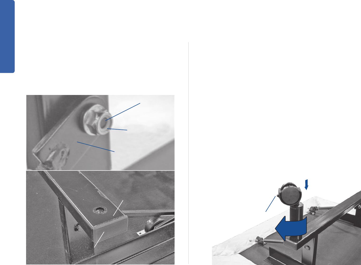
11 Tighten Bolts and Cap Frame Ends
• Firmly tighten all eight (8) bolts in base assembly and leg support
assemblies. Tighten nylon insert locking nuts on leg support
assemblies until snug. The end of the stud is indented approximately
1/16” from outside edge of nylon insert (see photo A)
• Do not overtighten
• Insert plastic end caps into (4) cross frame ends (see photo B)
12 Add Legs
• Your Sleep Number
®
adjustable base comes with 4-inch legs
and four (4) casters. Screw the legs into the base assembly
• Optional: Insert four (4) casters in ends of legs (casters add 2½ inches
to overall base height)
NOTE: Once bed is positioned, make sure caster brake is engaged.
Caster Brake
Plastic End Cap
(Installed)
Cross Frame End
Missing photo A
Cross Frame End
Outside Edge of
Nylon Insert
Flat End of Leg
Support Assembly
A
B
Full/Queen Assembly
10

13 Flip Base
• Untie electrical power cord and extend out
• Carefully rotate adjustable base onto right-side-up position
• Plug electrical power cord into wall
14 Install Bushings
• Install two (2) mattress retainer bushings in locator pin holes by
pressing firmly into place
15 Install Mattress Retainer Bar
• Insert into bushings and press down until horizontal section is
firmly against deck assembly
Bushings
(Installed)
Mattress Retainer Bar
FootFoot
You’re Done! Next Step
u
Hand Control Function
u
Page 21
Full/Queen Assembly
11

2 Cut and Remove Plastic Bands on Box 1
CAUTION: Exercise caution when using sharp tools. The danger of
injury is possible if tools are not used properly.
1 Locate Two Box 1s and Two Box 2s
NOTE: You will do steps 1–13 for both bases for King/Cal King/Split
King models.
Boxes are marked as shown.
2
2
1
1
King/Cal King/Split King Base Assembly
King/Cal King/Split King Assembly
12

4 Unfold Deck Assembly
3 Open Box and Remove Packaging
• Open Box 1 to reveal one (1) adjustable base deck assembly
• Remove protective plastic covering from adjustable deck assembly
King/Cal King/Split King Assembly
13

5 Position Deck Assembly
• Bottom side up
Boxes are marked as shown.
Hand Control Box
Hardware Box
6 Cut Plastic Bands and Open Box 2
• Open hardware box and verify contents
• Open hand control box and verify contents
• Cut zip ties and remove edge packing and mattress retainer bar
Tags located at head end
King/Cal King/Split King Assembly
14

King/Cal King Split King
Hand Control
1 2
Wrench
1 1
Bolt
16 16
Leg Support Assembly
4 4
Plastic End Cap
8 8
Bushing
4 4
4-inch Leg
8 8
Caster
8 8
Headboard Bracket Assembly Kit
2 2
DC Connector Cable*
* For use with King or Cal King bases only to allow (1) hand control to operate both bases.
Only one included in one Box 2.
1 0
Mattress Retainer Bar
Zip-tied to frame
2 2
Parts and Components
King/Cal King/Split King Assembly
15

7 Remove Base Assembly From Box
• Carefully remove steel base assembly from box
• Match head end of base assembly (indicated by labels on both
components) with head end of deck assembly. Position steel base
assembly so that four (4) side holes (2 left, 2 right) line up with holes
in deck assembly. Insert bolts in diagonal fashion (numerical
sequence shown in photo) using wrench (included)
• Do not tighten
IMPORTANT SAFETY NOTICE: At least two (2) people are
recommended for handling and moving adjustable bed base.
8 Prepare Leg Support Assemblies
• Locate leg support assembly connections at the foot end of the
adjustable base (see photos at left and below)
• Remove nylon insert locking nuts and outside bushings
NOTE: Retain hardware for attachment of leg support assemblies.
1
4
3 2
Hole
Hole
Hole Hole
Leg Support
Assembly
Connections
Tags located at head end
Outside Bushing
Nylon Insert
Locking Nut
Steel Base Frame
King/Cal King/Split King Assembly
16

9 Position Flanges
• Position foot support flanges to line up with holes in deck
• Insert mounting bolts in flanges
• Do not tighten
NOTE: Flanges are universal for left or right. They can be turned and
manipulated to fit either side of the base.
10 Install Leg Support Assemblies
• Install flat end of leg support assembly on stud in steel base assembly
• Reinstall outside bushing and nylon insert locking nut
• Do not tighten
• Repeat for other leg support assembly
Foot
Support
Flange
Flat end of
Leg Support
Assembly
Leg Support Assembly
Outside Bushing
Steel Base Frame
Stud
Flat end of
Leg Support
Assembly
Nylon Insert
Locking Nut
King/Cal King/Split King Assembly
17

13 Repeat Assembly for Second Base
• For King and Cal King models, repeat steps 1–12 before proceeding
to step 14
• For Split King models, repeat steps 1–12, then proceed to step 15
(skip step 14)
Caster Brake
11 Tighten Bolts and Cap Frame Ends
• Firmly tighten all eight (8) bolts in base assembly and leg support
assemblies. Tighten nylon insert locking nuts on leg support
assemblies until snug. The end of the stud is indented approximately
1/16” from outside edge of nylon insert (see photo A)
• Do not overtighten
• Insert plastic end caps into four (4) cross frame ends (see photo B)
12 Add Legs
• Your Sleep Number
®
adjustable base comes with 4-inch legs
and four (4) casters. Screw the legs into the base assembly
• Optional: Insert four (4) casters in ends of legs (casters add 2½ inches
to overall base height)
NOTE: Once bed is positioned make sure caster brake is engaged.
Plastic End Cap
(Installed)
Cross Frame End
Missing photo A
Cross Frame End
Outside Edge of
Nylon Insert
Flat End of Leg
Support Assembly
A
B
King/Cal King/Split King Assembly
18

14 Install Connector Cable
(King and Cal King models only)
• A DC connector cable connects both bases for operation with one
hand control
• Carefully position both bases approximately 2 feet apart on edge,
with underside of both bases facing inward. Be sure both bases are
oriented the same way (heads together, foot ends together). Locate
base equipped with the wired hand control. Unplug hand control
and set aside
• Plug first dual DC connector cable plug into the insertion receptacle
on the first motor
IMPORTANT SAFETY NOTICE: Insert carefully. Line up pins in plug
with holes in insertion receptacle. Push in as far as plug will go.
• Plug second dual DC connector cable plug into the second insertion
receptacle following the same instructions
• Insert DC wired hand control plug into dual DC connector
cable receptacle
• Carefully turn both bed bases over to right-side-up position.
Align the heads of both bases side by side to create the King or Cal
King unit
• Untie electrical power cord and extend out, then plug into wall
• Do not obstruct power or hand control cords
• Proceed to Step 16
Installed Dual DC
Connector Plug
Insertion Receptacle
Dual DC
Connector Cable
(to hand control)
Hand Control
Plug
Dual DC Connector
Plug (for second base)
Location of Hand Control
Hand Control
King/Cal King/Split King Assembly
19

15 Flip Base
• Untie electrical power cord and extend out
• Carefully turn adjustable base over to right-side-up position
• Plug electrical power cord into wall
16 Install Bushings
• Install two (2) mattress retainer bushings in locator pin holes by
pressing firmly into place
17 Install Mattress Retainer Bar
• Insert into bushings and press down until horizontal section is
firmly against deck assembly
• Repeat for second base
Bushings
(Installed)
Foot
Mattress Retainer Bar
Foot
King/Cal King/Split King Assembly
20

Foot Up Button
Press and hold to raise the
foot section.
Head Up Button
Press and hold to raise the
head section.
Head/Foot Up Button
Press and hold to raise the head
and foot sections simultaneously.
Head Down Button
Press and hold to lower
the head section.
Head/Foot Down Button
Press and hold to lower the head
and foot sections simultaneously.
Foot Down Button
Press and hold to lower
the foot section.
Adjustable Base Hand Control Function
Hand Control Function
21

2 Position Headboard Channel Connector
NOTE: For Full size beds use inner mounting holes. For Queen, King,
Cal King and Split King beds, use outer mounting holes
• Position headboard channel connector so the flat side is flush
against bed base frame. Attach headboard channel connector to the
bed base frame using two (2) 1½-inch long hex head bolts/nuts
1 Install Optional Headboard Brackets
NOTE: Headboard brackets are only needed for non-freestanding
headboards
• Use the hand control to raise the head section of the bed to access
the bed base frame
• Locate the headboard bracket assembly kit. On one (1) side of
the bed base frame, locate two (2) holes for headboard channel
connector mounting
(2) Headboard Channel Connector
Mounting Holes
Queen, King & Cal King size
base Mounting Holes
Full size base
Mounting Holes
Headboard Channel
Connector
(2) 1½” Long
Hex Head Bolts
and Nuts
Headboard Bracket Assembly (optional)
22
Headboard Bracket Assembly

4 Attach Headboard Bracket Flange
• Attach one (1) headboard bracket flange to one (1) of the
headboard bracket channels with two (2) 1-inch long hex
head bolts/nuts
• Repeat procedure to attach the other headboard bracket flange
• Slide headboard bracket assemblies (in or out) to achieve a
distance of 1½inches (38.1mm) to 2inches (50.8mm)
between the edge of the bed base and headboard
bracket flanges
3 Attach Headboard Bracket Channel
• Using two (2) 3-inch long carriage bolts/nuts, attach one (1)
headboard bracket channel to one (1) headboard channel
connector. Hand-tighten bolts/nuts (loosely) to allow adjustment
of the headboard bracket channels
Headboard Channel
Connector
Headboard Bracket
Channel
(2) 1” Long
Hex Head Bolts
and Nuts
Headboard
Bracket Flange
Slide headboard bracket
assemblies in or out
to achieve position
1.5” to 2”
Headboard Bracket Assembly
23

6 Install Headboard
• Securely install your headboard
IMPORTANT SAFETY NOTICE: The bottom of the headboard cross
member must be positioned so that there is no more than 3inches
(76.2mm) between the headboard and the top of the mattress.
Do not exceed 3 inches (76.2mm) in order to avoid a person or pet
being caught in the space (referenced below) while the bed is in
motion. Failure to follow these instructions could result in serious
personal injury or death.
5 Adjust and Secure
• Firmly tighten the 3-inch long carriage bolts on both headboard
bracket channels
• Measure the distance (center-to-center) between the mounting holes
in the headboard
• Measure the center-to-center distance between the mounting slots
of the headboard bracket flanges
• If headboard bracket flange adjustment is required to accept the
headboard, remove the 1-inch long hex head bolts and move
flanges side-to-side for the adjustment. Reinstall bolts. Tighten all
headboard mounting bolts
Remove 1-inch long hex head bolts and relocate
flanges to achieve center-to-center distance required
for headboard mounting holes.
Measure flange slots center-to-center
to check headboard hole location.
3” MAX.
CAUTION: Headboard cross member location must not exceed
3inches (76.2mm) from the top of the mattress.
24
Headboard Bracket Assembly

IMPORTANT: READ THE FOLLOWING INFORMATION CAREFULLY
BEFORE USING THIS PRODUCT
This SLEEP NUMBER
®
adjustable base has been quality engineered with
design features to ensure comfort and safety when operated properly.
ELECTRICAL GROUNDING
This product is equipped with a polarized or grounded electrical power cord.
The power cord will only fit into a grounded electrical surge protection device
(not included) or a grounded electrical outlet.
IMPORTANT SAFETY NOTICE: For optimum adjustable bed operation,
use a grounded electrical surge protection device (not included). Failure to
use a surge protection device could compromise safety or cause
product malfunction.
WARRANTY WARNING
Do not attempt to open the motor or hand control. The product warranty
will be void if these components are tampered with. Do not attempt to alter
component wiring or adjust or modify the structure of the product in any way
or the warranty will be void. Any repair or replacement of adjustable bed parts
must be performed by authorized personnel.
LUBRICATION
This product is designed to be maintenance free. The lift motors are
permanently lubricated and sealed—no additional lubrication is required. Do
not apply lubricant to lift motor lead screws or any nylon nuts or the bed may
inadvertently creep downward from the elevated position.
PRODUCT RATINGS
The bed lift motors are not designed for continuous use. Reliable operation
and full life expectancy will be realized as long as the lift motors do not
operate any more than five (5) minutes over a thirty (30) minute period, or
approximately 15% duty cycle. Any attempt to circumvent or exceed product
ratings will shorten the life expectancy of the product and may void the
warranty.
The recommended weight restrictions for Sleep Number
®
adjustable bases
are Full, Queen: 450 lb (204 kg); King, Cal King, Split King: 900 lb (408 kg).
The bed will structurally support the recommended weights distributed
evenly across the head and foot sections. This product is not designed to
support or lift this amount in the head or foot sections alone.
NOTE: Exceeding the recommended weight restrictions could damage the
adjustable bed and void the warranty. For best performance, consumers
should enter and exit the adjustable bed with the bed in the flat (horizontal)
position.
DO NOT SIT ON THE HEAD OR FOOT SECTIONS WHILE
IN THE RAISED POSITION.
UL (Underwriters Laboratories) listed components.
CFR 1633 approved for use with most mattresses.
Made in USA.
SMALL CHILDREN / PETS WARNING
After the bed is unboxed, immediately dispose of packaging material as it can
smother small children and pets. To avoid injury, children or pets should not
be allowed to play under or on the bed. Children should not operate this bed
without adult supervision.
HOSPITAL USE DISCLAIMER
This bed is designed for in-home use only. It is not approved for hospital use
and does not comply with hospital standards. Do not use this bed with tent
type oxygen therapy equipment or use near explosive gases.
FCC COMPLIANCE
Electrical components are rated for 110/120 voltage, 60Hz, 3.9 amp.
Components meet Class B digital device rating (Part 15, FCC rules) for
residential use.
RAISING/LOWERING MECHANISMS
The raise/lower feature will emit a minimal humming sound during operation.
This is normal. During operation, the lift arm wheels make contact with
the platform support of the bed. This applies slight tension on the moving
components and resonance is reduced to a minimum level. If excessive
noise or vibration is experienced, reverse the movement action (up or down)
of the bed with the hand control. This should realign the bed’s activating
mechanisms to the proper operational position.
Advisory
Advisory
25

2-5-25 Warranty
In the event the SLEEP NUMBER
®
adjustable base fails to operate,
investigate the symptoms and possible solutions provided below.
No features of the adjustable bed will activate.
• Verify power cord is plugged into a working, grounded electrical outlet.
A grounded electrical surge protection device is recommended. Test
outlet by plugging in another working appliance.
• Unplug power cord, wait 30 seconds and plug in to reset electronic
components.
• Electrical circuit breaker may be tripped; check electrical service breaker
box to verify.
• Surge protection device may be defective.
Head or foot section will elevate, but will not return to the flat
(horizontal) position.
• Bed mechanism may be obstructed. Elevate bed and check for
obstruction. Remove obstruction.
• Head section may be too close to the wall.
Leggett & Platt, Incorporated (“L&P”) warrants this adjustable bed to the
consumer who is the original purchaser (the “purchaser”), subject to the
terms and conditions set forth herein. This warranty begins on the “warranty
commencement date” which is the date of purchase for new unused beds
and the date of manufacture for beds that have been used as floor or display
models. Thus, on a floor model bed, the warranty is a portion of the limited
25 year warranty.
FULL 2 YEAR WARRANTY
This adjustable bed is warranted against defects in workmanship or materials
for a period of two (2) years from the warranty commencement date. Upon
notice during the first two (2) years after the warranty commencement
date, L&P will repair or replace (at no cost to the purchaser) any defective
adjustable bed part, and L&P will pay all authorized labor and transportation
costs associated with the repair or replacement of any parts found to be
defective.
5 YEAR LIMITED WARRANTY
During the third through the fifth year from the warranty commencement
date, upon receipt of notice, L&P will replace any adjustable bed part found
to be defective. This limited five (5) year warranty shall not apply unless the
defective part is returned to L&P within ten (10) days of purchaser’s receipt of
the replacement part. Purchaser shall pay all service and transportation costs
related to the replacement of the defective part.
25 YEAR LIMITED WARRANTY
Upon notice during the sixth year through the twenty-fifth year from the
warranty commencement date, L&P will replace, upon terms and conditions
set forth in this paragraph, any mechanical bed part found to be defective.
Electronics, electrical components, drive motors and massage motors
are excluded. This limited twenty-five (25) year warranty shall not apply
unless the defective part is returned to L&P within ten (10) days of purchaser’s
receipt of the replacement part. In years 6–25, purchaser shall pay all service
and transportation costs related to the replacement of the defective part.
Troubleshooting
Troubleshooting/Warranty
26

Additional Terms and Conditions
This warranty does not apply; (a) to any damage caused by the purchaser;
(b) if there has been any repair or replacement of adjustable bed parts by
unauthorized personnel; (c) if the adjustable bed has been mishandled
(whether in transit or by other means), subjected to physical or electrical
abuse or misuse, or otherwise operated in any manner inconsistent with
the operation and maintenance procedures outlined in this document and
this warranty; (d) to damage to mattresses, fabric, cables, electrical cords
or items supplied by dealers. Contact the dealer for warranty information
on these items; (e) if there has been any modification to the adjustable bed
without prior written consent by L&P; (f) to costs for unnecessary service calls,
including costs for in-home service calls solely for the purpose of educating
the consumer about the adjustable bed or finding an unsatisfactory power
connection; (g) if the recommended weight restriction is not followed (refer to
advisory section), the warranty will be void.
Repairs to or replacement of an adjustable bed or its components under
the terms of this limited warranty will apply to the original warranty
period and will not serve to extend such period.
The decision to repair or to replace defective parts under this warranty shall
be made, or cause to be made, by L&P at its option and in its sole discretion.
Repair or replacement shall be the sole remedy of the purchaser. There
shall be no liability on the part of L&P for any special, indirect, incidental, or
consequential damages or for any other damage, claim, or loss not expressly
covered by the terms of this warranty.
This limited warranty does not include reimbursement for inconvenience,
removal, installation, setup time, loss of use, shipping, or any other costs or
expenses. Leggett & Platt or its service technicians shall not be responsible
for moving furniture or any other items not attached to the adjustable bed in
order to perform service on the adjustable bed.
It is the sole responsibility of the purchaser to provide adequate space and
accessibility to the adjustable bed. In the event that the technician is unable
to perform service due to lack of accessibility, the service call will be billed to
the purchaser and the service will have to be rescheduled.
L&P makes no other warranty whatever, express or implied, and all
implied warranties of merchantability and fitness for a particular purpose
are disclaimed by L&P and excluded from this agreement. Some states
do not allow the exclusion or limitation of incidental or consequential
damages, so the above limitation or exclusion may not apply to every
purchaser.
This warranty gives the purchaser specific legal rights, and the purchaser may
also have other rights, which may vary from state to state. This warranty is
valid in all 50 states, Puerto Rico, and Canada.
CONTACT INFORMATION: Select Comfort, Customer Service Department,
6105 Trenton Lane North, Minneapolis, MN 55442, 800-790-9298.
Terms and Conditions
27

If you ever have product questions or
need additional assistance obtaining
optimal comfort, please visit us at:
mygoldservice.com
or call
1.800.790.9298
Representatives are available
(Central Standard Time):
Monday–Friday 8 a.m. – 8 p.m.
Saturday 8:30 a.m. – 5 p.m.
Sunday Closed
Help is just a click or
phone call away
9800 59TH AVENUE NORTH
MINNEAPOLIS, MN 55442
120478
7/14
