
OPERATOR, MAINTENANCE
AND PARTS MANUAL
Models FH and FH-R
• Single Discharge
• Dual Discharge
www.roadwidenerllc.com

CONTENTS
GENERAL
INFORMATION ..................................3
Introduction...................................3
Read This Manual Prior to Operation .........3
Contact Information ..........................4
Limited Warranty.............................4
Warranty .....................................4
Limitations ....................................4
Items Not Covered..............................5
Other Limitations ...............................5
Model and Serial Tag .........................5
6RGEKŞECVKQPU .................................6
Crating and Uncrating Instructions . . . . . . . . . . . 8
Assembly .....................................8
Optional Equipment...........................8
Roller Extension...............................8
Curb Attachment .............................9
Installation ....................................9
Push Plate....................................13
Pairing the Remote Control...................13
Hardware Torque Chart......................14
EC Declaration of Conformity................15
SAFETY ........................................16
Safety Decals ................................19
Control Area Safety..........................23
TRANSPORTING THE ROAD
WIDENER.......................................24
Lift Test......................................24
Loading......................................25
JOBSITE
PREPARATION..................................27
OPERATION ....................................36
Curb Attachment Operation..................40
Disconnecting Hydraulic and Electrical
Lines.........................................42
Hydraulic Solenoid Manual Override .........42
Curb Attachment Operation..................49
Disconnecting Hydraulic Lines...............50
MAINTENANCE ................................51
Periodic Maintenance Chart..................51
Greasing the Machine........................52
Belt Start-Up and Maintenance ..............53
Checking Hydraulic Oil Level ................54
Adjusting Conveyor Belt Tension.............54
Hopper Rubber Flashing to Conveyor Belt
Clearance....................................55
Adjusting Conveyor Belt Drive Chain ........55
Checking Hydraulic Hoses...................56
Cleaning After Operation ....................56
Remote Battery Replacement.................56
TROUBLESHOOTING...........................58
ILLUSTRATED PARTS LIST....................62

3
GENERAL
INFORMATION 1
Introduction
Congratulations on your purchase of the Road Widener
material distribution machine. We would like to thank you
for purchasing the Road Widener. The Road Widener was
engineered and constructed to provide years of productive
results on the jobsite.
Manufacturer’s Limited Warranty terms are available if the
machine is registeredwithin 60 daysof delivery. Registration
can be completed online atwww.roadwidenerllc.com.
Please watch our operational and instructional video for
important instructions and tips on how to operate your
attachment.The video can be found on our website under
the RESOURCES page.
Password: widenroad
Read This Manual Prior
to Operation
This manual contains safety information, operating
instructions, lubrication and maintenance procedures, and
a spare parts list. Read this manual carefully to learn how
to operate and perform service on the machine correctly.
Failure to do so could result in personal injury or equipment
damage. In addition to the manual, a service and operation
video is available at www.roadwidenerllc.com and must be
viewed before operating the machine.
The Road Widener is available in either a left-hand, right-
hand or dual discharge model. All safety, operation and
maintenance procedures are the same whether you have
a left-hand, right-hand or dual discharge Road Widener
machine.
This manual should be kept nearby and be readily
accessible to the operator at all times. If this manual is lost
or damaged, contact your authorized Road Widener dealer
or the Road Widener LLC corporation immediately to order
a replacement.
Some photographs or illustrations in this manual may show
details or attachments that may be different from your
machine. Guards and covers may have been removed
for illustrative purpose. Guards should never be removed
during operation.
Operating procedures in this manual are basic. They
help with developing the skills and techniques required to
operate the machine efciently and economically. Skill level
and techniques will develop as the operator gains more
knowledge of the machine and its capabilities.

OPERATOR, MAINTENANCE AND PARTS
4
1
GENERAL INFORMATION
Contact Information
For additional information on Road Widener, go to
www.roadwidenerllc.com. To ask a service or sales question,
or to order spare parts, contact Road Widener at:
Road Widener LLC
514 Wells Street, Suite 1W
Delaeld, WI 53018
www.roadwidnenerllc.com
Sales E-mail: [email protected]
Parts E-mail: [email protected]
Phone: 844-494-3363
Limited Warranty
OTE: N To be eligible for coverage under this Limited
Warranty (including with respect to any products,
parts or labor), you must complete and return to
Road Widener the Warranty Registration for this
product. The Warranty Registration can be found
on Road Widener’s website (www.roadwidenerllc.
com). Any questions or requests for assistance
in completing the Warranty Registration must be
directed to Road Widener’s Parts Department.
WAR RAN T Y
Subject to the limitations, exclusions, and claims procedures
set forth herein, ROAD WIDENER LLC warrants to the rst
original purchaser from ROAD WIDENER LLC or its authorized
distributor that this product will be free from material defects in
material and workmanship under normal use and service during
the warranty period.
If a material defect in material or workmanship is found, you must
notify your authorized ROAD WIDENER distributor or ROAD
WIDENER LLC in writing during the warranty period. ROAD
WIDENER LLC or an authorized distributor will, at ROAD
WIDENER LLC’s option, repair or replace the product or any
part of the product that ROAD WIDENER LLC determines has
failed to conform to the warranty during the warranty period, or
refund to the purchaser the purchase price received by ROAD
WIDENER LLC for the product or part in question.
The warranty period will begin upon initial delivery of the product
by ROAD WIDENER LLC or its authorized distributor to the
rst original purchaser, as such delivery date is identied in the
invoice to the purchaser, and will expire (12) months following
such delivery date.
Replacement parts manufactured by ROAD WIDENER
LLC are covered for the remainder of the warranty period
applicable to the product in which such parts are installed.
ROAD WIDENER LLC reserves the right for it or its authorized
distributor to utilize reconditioned, refurbished, repaired, or
remanufactured products or parts in the warranty replacement
process. Such products and parts will be reasonably
comparable in function and performance to an original product
or part.
ROAD WIDENER LLC reserves the right to repair any part
in lieu of replacing it. The purchaser shall, at its expense and
risk, return defective products or parts, after pre-authorization
by ROAD WIDENER LLC, to the distributor or manufacturing
facility specied in such pre-authorization. This Limited Warranty
covers only repair or replacement at such facility and does not
include eld service, travel, or other expenses, and does not
include normal maintenance of products. Parts not manufactured
by ROAD WIDENER LLC and purchased by ROAD
WIDENER LLC or an authorized distributor are not warranted
by ROAD WIDENER LLC but may carry a warranty from the
manufacturer. ROAD WIDENER LLC will pass the warranty on
to the purchaser if permitted by the manufacturer and reasonably
practicable.
The purchaser is responsible for the costs and risks of
transporting the product or part from such facility following review
of the warranty claim or warranty service.
LIMITATIONS
1 ] ROAD WIDENER LLC has no obligation for any defects
caused in whole or in part by misuse, abuse, abnormal
use, neglect, tampering, misapplication, negligence,
damage in transit, damage due to environmental or natural
elements or accidents. ROAD WIDENER LLC has
no obligation for failure to maintain, store, install, or use
products or parts in accordance with ROAD WIDENER
LLC’s most current operating instructions.
2 ] ROAD WIDENER LLC has no obligation under this
Limited Warranty if there has been unauthorized service or
alteration of the product or parts.
3 ] ROAD WIDENER LLC has no obligation under this Limited
Warranty for defects caused in whole or in part by any
replacement parts or attachments not manufactured by or
approved by ROAD WIDENER LLC.
4 ] ROAD WIDENER LLC has no obligation under this
Limited Warranty if there has been a failure to conduct
normal maintenance and operating service including,
without limitation, providing lubricants, uids, inspections,
or adjustments.
5 ] ROAD WIDENER LLC has no obligation under this
Limited Warranty if there has been unreasonable delay,
as determined by ROAD WIDENER LLC, in making the
applicable products or parts available upon notication of
a service notice ordered by same.
6 ] This Limited Warranty sets forth the original purchaser’s
sole remedy, and ROAD WIDENER LLC’s sole
obligation, in connection with the ROAD WIDENER
LLC product covered by the Limited Warranty. ROAD
WIDENER LLC will not reimburse the purchaser for
any expenses incurred by the purchaser in repairing

OPERATOR, MAINTENANCE AND PARTS
5
GENERAL INFORMATION
or replacing products or parts unless an authorized
representative of ROAD WIDENER LLC approves
such costs in advance in writing. Any oral or written
description of a product or part is for the sole purpose
of identifying it and shall not be construed as an express
warranty. Any assistance ROAD WIDENER LLC or
its authorized distributor provides outside the terms or
limitations of this Limited Warranty does not constitute a
waiver of such terms or limitations, or extend or revive the
warranty. The limitations in this Limited Warranty apply
notwithstanding any failure of the essential purpose of the
limited remedies.
7 ] This Limited Warranty extends only to the rst original
purchaser, and is not transferable.
8 ] If any provision of this Limited Warranty shall be
determined to be invalid or unenforceable under any
applicable law, such provision shall be deemed null and
void to the extent of such invalidity or unenforceability and
the remainder of the Limited Warranty shall continue in full
force and effect.
9 ] Used products or used parts of any kind including, without
limitation, products that have been used personally or in
demonstration by an authorized distributor, are not covered
by this Limited Warranty, and there is NO WARRANTY on
such products or parts.
10 ] This Limited Warranty does not apply if defects are caused
in whole or in part by paint nish, corrosion, controller
keyboards, or consumables including, without limitation,
uids, lters, belts, hoses, and replaceable teeth.
11 ] This Limited Warranty does not apply if the claim is due
in whole or in part to normal wear and tear or operation
of the product outside ROAD WIDENER LLC’s
recommended operating parameters.
OTHER LIMITATIONS
The purchaser must satisfy the following obligations in order
to be eligible for coverage by this Limited Warranty. Prior to
using or permitting use of the products, the purchaser shall
determine the suitability of the products for the intended use
and the purchaser assumes all risk and liability whatsoever in
connection therewith. The purchaser shall familiarize itself with
and comply with all laws and regulations now or hereafter in
effect and applicable to the purchase, transport, use, supply,
storage, sale, offer for sale, lease, offer for lease, and/or
disposal of the products. The purchaser shall maintain and
provide to ROAD WIDENER LLC on request complete and
accurate service records for products with respect to which the
purchaser makes a warranty claim. The purchaser shall cause
any installation to be performed by an authorized distributor
of ROAD WIDENER LLC in accordance with product
specications, including torque.
THE EXPRESS WARRANTY DESCRIBED HEREIN IS
EXCLUSIVE AND IN LIEU OF ALL OTHER WARRANTIES
INCLUDING, WITHOUT LIMITATION, ANY IMPLIED
WARRANTIES OF MERCHANTABILITY, NON-
INFRINGEMENT OR FITNESS FOR A PARTICULAR
PURPOSE. ROAD WIDENER LLC DISCLAIMS AND
EXCLUDES ALL OTHER EXPRESS AND IMPLIED
WARRANTIES.
ROAD WIDENER LLC SHALL NOT BE LIABLE TO THE
PURCHASER, OR TO ANYONE CLAIMING UNDER
THE PURCHASER, FOR ANY OTHER REMEDIES,
OBLIGATIONS OR LIABILITIES IN CONNECTION
WITH PRODUCTS, THEIR USE OR PERFORMANCE
INCLUDING, WITHOUT LIMITATION, REMEDIES,
OBLIGATIONS, OR LIABILITIES ARISING OUT
OF BREACH OF CONTRACT OR WARRANTY,
NEGLIGENCE, OR OTHER TORT OR ANY THEORY OF
STRICT LIABILITY, WITH RESPECT TO THE PRODUCTS
OR ROAD WIDENER LLC’S ACTS OR OMISSIONS OR
OTHERWISE. No sales representative, distributor or other
party is authorized to modify or add to this Limited Warranty
in any manner without ROAD WIDENER LLC’s prior written
permission. No sales representative, distributor or other party is
authorized to bind ROAD WIDENER LLC to any representation
or warranty concerning the products except as specically set
forth in this Limited Warranty.
IN NO EVENT, WHETHER AS A RESULT OF BREACH OF
CONTRACT OR WARRANTY OR ALLEGED NEGLIGENCE
OR LIABILITY WITHOUT FAULT, SHALL ROAD WIDENER
LLC BE LIABLE FOR SPECIAL, INDIRECT, INCIDENTAL,
OR CONSEQUENTIAL DAMAGES INCLUDING, WITHOUT
LIMITATION, LOSS OF PROFIT OR REVENUE, COST OF
CAPITAL, COST OF SUBSTITUTED OR REPLACEMENT
EQUIPMENT, FACILITIES OR SERVICES, DOWNTIME
COSTS, LABOR COSTS OR CLAIMS OF CUSTOMERS,
PURCHASERS OR LESSEES FOR SUCH DAMAGES,
EVEN IF ROAD WIDENER LLC WAS ADVISED OF THE
POSSIBILITY OF SUCH DAMAGES. IN NO EVENT WILL
ROAD WIDENER, LLC BE LIABLE FOR AMOUNTS IN
EXCESS OF THE PURCHASE PRICE OF THE PRODUCT
RECEIVED BY ROAD WIDENER LLC.
Model and Serial Tag
The model and serial number tag is located on the left side
of the hopper. Refer to this tag when needing any warranty
or service assistance. Also refer to this tag when ordering
any spare parts. This will help ensure that the correct part
is ordered.
1

OPERATOR, MAINTENANCE AND PARTS
6
6RGEKŞECVKQPU
Single Discharge Unit
Width of FH and FH-R Single Discharge Road Wideners 125 in. (3,175 mm)
Height of FH and FH-R Single Discharge Road Wideners 51 in. (1,300 mm)
Length of FH and FH-R Single Discharge Road Wideners 98 in. (2,489 mm)
Widths of Shoulders of Road Widening Material That Can Be Laid Down 12 in. (305 mm) to 48 in. (1,219 mm)
Number of Side Exit Chutes 1
Gross Weight of FH Single Discharge Road Wideners 2,900 lb (1,315 kg)
Height of Push Rollers 21 in. (530 mm)
Extra Amount Push Rollers Can Extend 12 in. (305 mm)
Conveyor Belt Type Rubber
Conveyor Belt Length and Width 8 ft (2.4 m) x 20 in. (508 mm)
Conveyor Speed Range 0-350 ft/min (1.8 m/sec)
Head and Tail Drum Diameter 10 in. (254 mm)
Typical Working Pressure 3,000 psi (207 bar)
Flow Rate 17.5 - 24.2 gal/min (79.6 - 111 l/min)
Hydraulic Fittings JIC and SAE
Maximum and Minimum Feed Rates 2.0 tons/hr (1.8 tonnes/hr)
Maximum Lump Size of Road Widening Material 10 in. (254 mm)
Optimum Traveling Speed Range While Laying Down Road Widening Material 0.5 to 1.5 mph (8.0 to 2.4 km/hr)
1
GENERAL INFORMATION

OPERATOR, MAINTENANCE AND PARTS
7
Dual Discharge Unit
Width of FH and FH-R Dual Discharge Road Wideners 138 in. (3,505 mm)
Height of FH and FH-R Dual Discharge Road Wideners 51 in. (1,300 mm)
Length of FH and FH-R Dual Discharge Road Wideners 98 in. (2,489 mm)
Widths of Shoulders of Road Widening Material That Can Be Laid Down 12 in. (305 mm) to 48 in. (1,219 mm)
Number of Side Exit Chutes 2
Gross Weight of FH Dual Discharge Road Wideners 3,400 lb (1,542 kg)
Height of Push Rollers 21 in. (530 mm)
Extra Amount Push Rollers Can Extend 12 in. (305 mm)
Conveyor Belt Type Rubber
Conveyor Belt Length and Width 9.5 ft (2.9 m) x 21 in. (533 mm)
Conveyor Speed Range 0-350 ft/min (1.8 m/sec)
Head and Tail Drum Diameter 10 in. (254 mm)
Typical Working Pressure 3,000 psi (207 bar)
Minimum Flow Rate 17.5 - 24.2 gal/min (79.6 - 111 l/min)
Hydraulic Fittings JIC and SAE
Maximum and Minimum Feed Rates 2.0 tons/hr (1.8 tonnes/hr)
Maximum Lump Size of Road Widening Material 10 in. (254 mm)
Optimum Traveling Speed Range While Laying Down Road Widening Material 0.5 to 1.5 mph (8.0 to 2.4 km/hr)
1
GENERAL INFORMATION

OPERATOR, MAINTENANCE AND PARTS
8
Crating and Uncrating
Instructions
Type FH Single Discharge & Dual Discharge and FH-R
Single Discharge & Dual Discharge Road Widener
machines are generally shipped on an open, atbed truck.
For exports, the machines are packaged in shipping crates
that are designed to ensure that the components will not
be damaged during transport. Use caution when unpacking
the shipping crates as the contents may have shifted during
transit.
Assembly
The Road Widener machines come fully assembled from
the factory; however, some accessories weigh more than
30 lb (15 kg). When lifting accessories or components
more than 30 lb (15 kg), Road Widener recommends that
a minimum of 2 people and appropriate lifting devices be
used to assemble accessories or components.
Optional accessories weighing more than 30 lb (15 kg) are:
• Shoe Extension Kit
• Pintle Push Plate
• Push Roller Extensions (the push roller extensions are
not more than 30 lb (15 kg), but to install the push roller
extensions, lifting more than 30 lb (15 kg) is required)
Optional Equipment
Some optional equipment can be ordered from Road
Widener for your specic job if needed.
Roller Extension
If the rollers need to be extended closer to the dump
vehicle, roller extensions are available. The roller extensions
will extend the rollers an additional 12 in. (30 cm).
Figure 1: Roller Extension with Pins and Tubes Removed
1 ] Remove the pins holding the roller brackets to the
frame and remove the roller assembly.
2 ] Insert the roller extension tubes into the frame and pin
them in place.
3 ] Install the roller assembly into the extension tubes and
pin the roller assemblies in place.
1
GENERAL INFORMATION

OPERATOR, MAINTENANCE AND PARTS
9
Curb Attachment
The curb attachment extends the hopper and allows the
shoe to be extended up over a curb to spread material
outside the curb. The roller wheel acts as a guide and
rides on the inside of the curb. It can be installed on a right
discharge, a left discharge or either side of a dual discharge
machine.
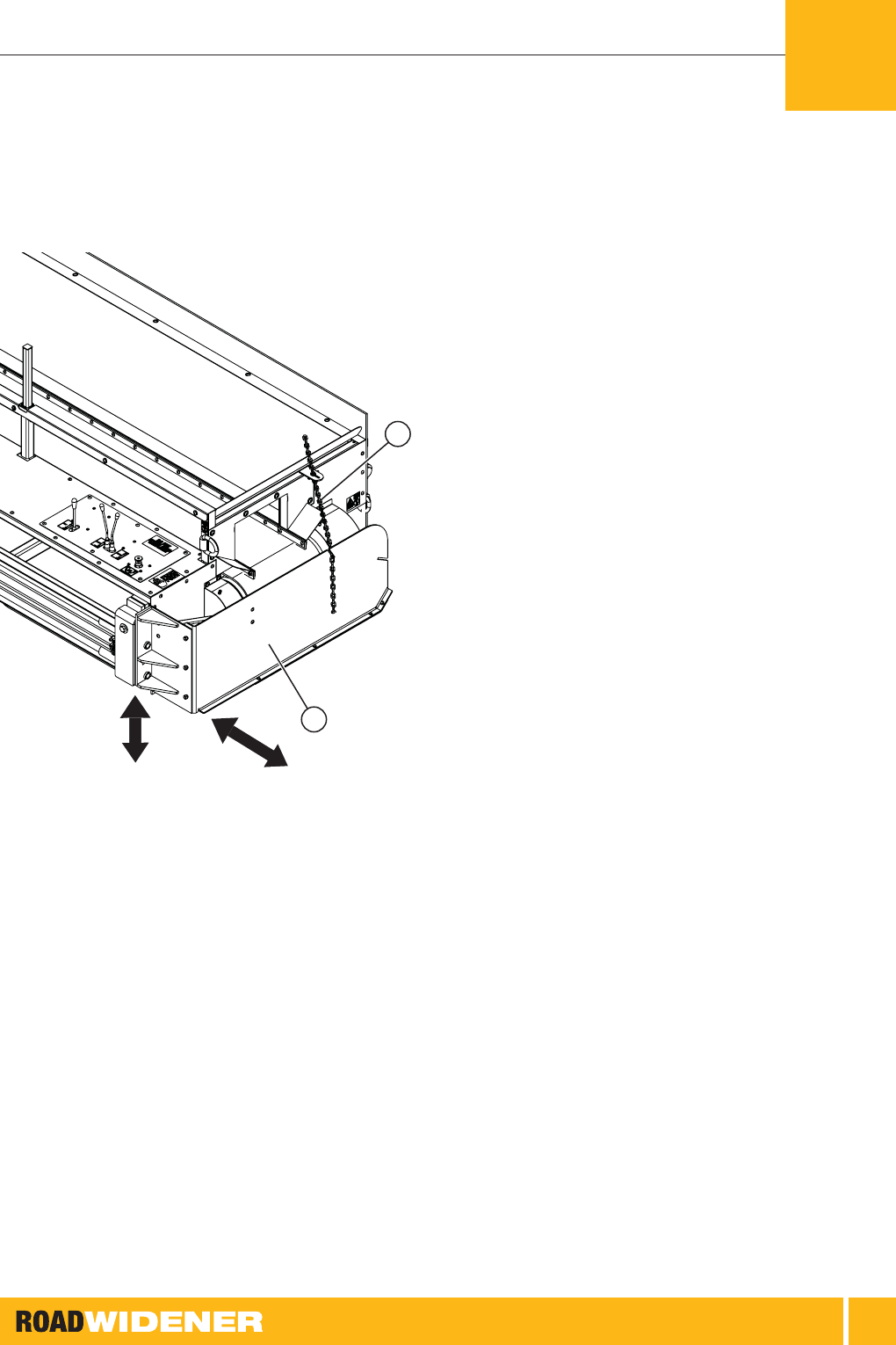
Figure 2: Curb Attachment Installed on Single Discharge Unit
INSTALLATION
OTE: N For easier installation have the machine
mounted on a skid steer. An assistant may be
required for the removal and the installation
of some of the parts. This procedure shows
mounting the curb attachment onto a right
side single discharge machine. Mounting on
a left side discharge or a dual discharge is
similar.
1 ] Park the machine on a at, level surface.
3
4
2
1
Figure 3: Shoe Hardware Removal
1. Support Bracket Socket Head Screws
2. Shoe Mounting Bolts and Locknuts
3. Chain
4. Shoe
2 ] Remove the 2 bolts for the support bracket.
3 ] Remove the shoe mounting bolts and locknuts.
4 ] Unhook the chain and remove the shoe.
1
GENERAL INFORMATION

OPERATOR, MAINTENANCE AND PARTS
10
Figure 4: Shoe Removal
Figure 5: Discharge Plate Removal
5 ] On dual discharge units remove the closure plate if
required.
1
1
3
2
Figure 6: Chute Guide Plate
1. Socket Head Cap Screws
2. Outer Mounting Bolts
3. Inner Mounting Bolts
1
GENERAL INFORMATION

OPERATOR, MAINTENANCE AND PARTS
11
6 ] Remove the 4 socket head cap screws.
7 ] Remove the 2 outer mounting bolts.
8 ] Remove the 2 inner mounting bolts.
Figure 7: Chute Guide Plate Removal
9 ] Remove the chute guide plate.
Figure 8: Install Curb Attachment
10 ] Mount the curb attachment frame using the socket
head cap screws and the outer and inner mounting
bolts removed earlier.
1
GENERAL INFORMATION

OPERATOR, MAINTENANCE AND PARTS
12
3
2
2
2
1
Figure 9: Spacer Plate
1. Spacer Plate
2. Spacer Plate Inner Mounting Bolts
3. Spacer Plate Outer Mounting Bolts
11 ] Mount the spacer plate between the Road Widener
frame and the curb attachment using 6 bolts.
2
4
3
1
5
Figure 10: Installing Shoe and Chains
1. Shoe
2. Bolt
3. Rear Chain
4. Front Chain
5. Hinge
12 ] Install the shoe to the frame using the bolt. The shoe
hinge must pivot up and down.
13 ] Install the front and rear chains.
1
GENERAL INFORMATION

OPERATOR, MAINTENANCE AND PARTS
13
Push Plate
The push plate is used to push the dump vehicle when
not using the rollers. It usually pushes on the trailer hitch
receiver or the pintle hitch.
Figure 11: Push Plate with Four Pre-threaded Holes
1 ] Hold the push plate in place on the front of the
machine.
2 ] Attach the push plate to the frame at the four
pre-threaded holes using the approved hardware.
Pairing the Remote
Control
Your remote control comes factory paired. Almost never
will you need to pair your remote and receiver. The system
will behave like it is not paired if less than 12 volts DC and
10 amps are not present. If for some reason your remote
does not work, double-check the power supply(s). In the
unlikely event that pairing is required, see the separate
paring instructions that were supplied with the machine or
go to www.roadwidenerllc.com for the pairing procedure.
Remote systems require a 12-volt DC accessory socket
to be a 10-amp continuous solid-state connection. Using
lower than a 10-amp DC accessory socket will cause the
machine to not function. The handheld remote requires (2)
AAA batteries and the host machine must deliver 12 volts
DC and 10 amps. Connect your machine to a known
power source to verify! A direct circuit to the host machine’s
battery with a solid-state 10-amp fused circuit is advisable if
your remote does not function at initial start-up. USB ports
and some machine circuits provide less than 10 amps; if
your host machine falls into this category, adding a circuit
will be required.
1
GENERAL INFORMATION

OPERATOR, MAINTENANCE AND PARTS
14
Hardware Torque Chart
Use this chart when tightening hardware to the proper torque value.
U.S. Standard Cap Screw Torque Values
SAE
GRADE
NUMBER
GRADE 1 OR 2 GRADE 5 GRADE 8
SIZE/
THREADS
PER INCH
TORQUE in.-lb (N·m) TORQUE in.-lb (N·m) TORQUE in.-lb (N·m)
THREADS DRY OILED PLATED DRY OILED PLATED DRY OILED PLATED
1/4 – 20 62 (7) 53 (6) 44 (5) 97 (11) 80 (9) 73 (8) 142 (16) 133 (15) 124 (14)
1/4 – 28 71 (8) 62 (7) 53 (6) 124 (14) 106 (12) 97 (11) 168 (19) 159 (18) 133 (15)
5/16 – 18 133 (15) 124 (14) 106 (12) 203 (23) 177 (20) 168 (19) 292 (33) 265 (30) 230 (26)
5/16 – 24 159 (18) 142 (16) 124 (14) 230 (26) 203 (23) 177 (20) 327 (37) 292 (33) 265 (30)
3/8 – 16 212 (24) 195 (22) 168 (19) 372 (42) 336 (38) 301 (34) 531 (60) 478 (54) 416 (47)
ft-lb (N·m) ft-lb (N·m) ft-lb (N·m)
3/8 – 24 20 (27) 18 (24) 16 (22) 35 (47) 32 (43) 28 (38) 49 (66) 44 (60) 39 (53)
7/16 – 14 28 (38) 25 (34) 22 (30) 49 (56) 44 (60) 39 (53) 70 (95) 63 (85) 56 (76)
7/16 – 20 30 (41) 27 (37) 24 (33) 55 (75) 50 (68) 44 (60) 78 (106) 70 (95) 62 (84)
1/2 – 13 39 (53) 35 (47) 31 (42) 75 (102) 68 (92) 60 (81) 105 (142) 95 (129) 84 (114)
1/2 – 20 41 (56) 37 (50) 33 (45) 85 (115) 77 (104) 68 (92) 120 (163) 108 (146) 96 (130)
9/16 – 12 51 (69) 46 (62) 41 (56) 110 (149) 99 (134) 88 (119) 155 (210) 140 (190) 124 (168)
9/16 – 18 55 (75) 50 (68) 44 (60) 120 (163) 108 (146) 96 (130) 170 (230) 153 (207) 136 (184)
5/8 – 11 83 (113) 75 (102) 66 (89) 150 (203) 135 (183) 120 (163) 210 (285) 189 (256) 168 (228)
5/8 – 18 95 (129) 86 (117) 76 (103) 170 (230) 153 (207) 136 (184) 240 (325) 216 (293) 192 (260)
3/4 – 10 105 (142) 95 (130) 84 (114) 270 (366) 243 (329) 216 (293) 375 (508) 338 (458) 300 (407)
3/4 – 16 115 (156) 104 (141) 92 (125) 295 (400) 266 (361) 236 (320) 420 (569) 378 (513) 336 (456)
7/8 – 9 160 (217) 144 (195) 128 (174) 429 (582) 386 (523) 343 (465) 605 (820) 545 (739) 484 (656)
7/8 – 14 175 (237) 158 (214) 140 (190) 473 (461) 426 (578) 379 (514) 675 (915) 608 (824) 540 (732)
1.0 – 8 235 (319) 212 (287) 188 (255) 644 (873) 580 (786) 516 (700)
910
(1,234)
819
(1,110)
728 (987)
1.0 – 14 250 (339) 225 (305) 200 (271) 721 (978) 649 (880) 577 (782)
990
(1,342)
891
(1,208)
792
(1,074)
NOTE:
• Dry torque values are based on the use of clean, dry threads.
• Oiled torque values have been reduced by 10% when engine oil is used as a lubricant.
• Plated torque values have been reduced by 20% for new plated cap screws.
• Oiled torque values should be reduced by 10% from dry when nickel-based antiseize compound is used as a lubricant.
• Cap screws which are threaded into aluminum may require a torque reduction of 30% or more.
• The conversion factor from ft-lb to in.-lb is ft-lb x 12 equals in.-lb.
1
GENERAL INFORMATION

OPERATOR, MAINTENANCE AND PARTS
15
EC Declaration of
Conformity
Single and Dual Discharge Road Wideners
Models FH & FHR (Full Hydraulic & Full Hydraulic Remote)
1
GENERAL INFORMATION

16
!
This safety alert symbol appears with most
safety statements. It means attention, become
alert, your safety is involved! Please read and
abide by the message that follows the safety alert symbol.
The words DANGER, WARNING, CAUTION and NOTICE
are used throughout this manual to highlight important
information.
Indicates a hazardous situation which, if not
avoided, will result in death or serious injury.
DANGER
!
Indicates a hazardous situation which, if not
avoided, could result in death or serious injury.
WARNING
!
Indicates a hazardous situation which, if not
avoided, could result in minor or moderate injury.
CAUTION
!
Indicates a situation which can cause damage to the Road
Widener, personal property, and/or the environment, or cause
the equipment to operate improperly.
NOTICE
OTE: N Indicates a procedure, practice or condition
that should be followed in order for the Road
Widener to function in the manner intended.
!
WARNING
Before starting and operating the
Road Widener, be sure to read and
understand the content and safety
messages within this manual as well as
the safety labels on the Road Widener.
The operator is responsible for safe
operation of the Road Widener. Be sure
all potential users of the Road Widener
also understand these instructions.
Always keep your Road Widener in
proper working condition.
SAFETY2

OPERATOR, MAINTENANCE AND PARTS
17
It is the operator’s responsibility to read and
understand the skid steer or wheel loader safety
messages and proper operation and capabilities.
Only qualied and responsible operators should
be permitted to operate the machinery.
WARNING
!
Know the total rated operating capacity of
the skid steer or wheel loader which you will
be attaching to the Road Widener. The total
operating capacity should exceed the weight of
the Road Widener.
WARNING
!
!
WARNING
Never operate the machine while under
the inuence of alcohol or drugs. Their
effect on vision and judgment make
operating the machine dangerous.
Road Widener machines should never be
operated with the casters off the ground.
Forward tipping may result. Road Widener
machines should be lifted off the casters while
loading and unloading only.
WARNING
!
Never operate the machine with the guards
missing or damaged. Tampering with or
modifying the guards may result in injury or
premature wear on the machine.
WARNING
!
!
WARNING
Before operating the machine, read the
skid steer or wheel loader operation
manual and know what the acceptable
grade requirements are. The Road
Widener attachment will usually add
to the drive machine’s stability. Road
Widener assumes no responsibility of
tipping due to the angle of use.
Never allow an operator to sit or stand on Road
Widener attachment while in operation. A non-
slip surface is provided near the attachment plate
for entering and exiting skid steer only. Horizontal
surfaces may support maintenance personnel.
This should only occur with machinery stopped
and fully disconnected from power source.
WARNING
!
2
SAFETY

OPERATOR, MAINTENANCE AND PARTS
18
!
WARNING
ALWAYS wear the appropriate personal
protective equipment as required by the
task at hand, including but not limited
to:
• Relatively tight and belted clothing
• Safety gloves
• Safety shoes/boots
• Safety eye glasses/goggles/shields
• Hearing protection, ear plugs
• Head protection, hard hats
Operating the machine requires the full
attention of the operator. Do not wear
radio or music headphones that may
interfere with jobsite communications
or monitoring the machine in operation.
!
WARNING
Use extreme caution when near rotating
parts. Rotating parts can entangle
hands, feet, hair, clothing and/or
accessories. Traumatic amputation or
severe laceration can result.
• Keep hands and feet away from
rotating parts.
• Tie up long hair and remove jewelry.
• Operate equipment with all guards in
place.
• DO NOT wear loose-tting clothing,
dangling drawstrings or items that
could become caught.
Stay clear of all moving parts, rollers,
conveyor belt and skid steer when the
Road Widener is in operation.
Do not drive the Road Widener through gravel piles or asphalt
spills. Material can accumulate inside the belt and the belt
rollers causing premature belt wear or belt failure.
NOTICE
Always be environmentally responsible.
• Follow the guidelines of the EPA or other governmental
agencies for the proper disposal of hazardous materials.
Consult the local authorities or reclamation facility.
• NEVER dispose of hazardous materials irresponsibly
by dumping them into a sewer, on the ground, or into
groundwater or waterways.
• Failure to follow these procedures may seriously harm the
environment.
NOTICE
Inspect all hoses, ttings and hydraulic components on both
the Road Widener attachment and the drive machine before
operation of the hydraulic system. Repair any problems that
are discovered.
NOTICE
Do not lift with material in the hopper.
NOTICE
2
SAFETY

OPERATOR, MAINTENANCE AND PARTS
19
Safety Decals
Read and understand all machines’ safety decals. Keep
safety decals in good condition. Replace all missing or
damaged safety decals. Replacement safety decals can be
ordered from Road Widener LLC.
Safety decals located on your machine contain important
and useful information that will help you operate your
equipment safely. To ensure that all decals remain in place
and in good condition, follow these instructions:
• Keep decals clean. Use soap and water, not mineral
spirits, abrasive cleaners or other similar cleaners that
will damage the decal.
• Replace any damaged or missing decals. When
attaching decals, the surface temperature of the metal
must be at least 40°F (5°C). The surface must also be
clean and dry. When replacing a machine component
with a decal attached, replace the decal also.
1
1
1
3
5
2
4
1
4 5321
Figure 12: Locations of Safety Decals – FH-R Single Discharge Models
2
SAFETY

OPERATOR, MAINTENANCE AND PARTS
20
1
1
1
2
2
4
1
3
3
4 5321
5
Figure 13: Locations of Safety Decals – FH-R Dual Discharge Models
2
SAFETY

OPERATOR, MAINTENANCE AND PARTS
21
1
1
1
2
4
1
4 5321
3
5
Figure 14: Locations of Safety Decals – FH Single Discharge Models
2
SAFETY

OPERATOR, MAINTENANCE AND PARTS
22
1
1
1
2
2
4
1
4 5321
3
3
5
Figure 15: Locations of Safety Decals – FH Dual Discharge Models
2
SAFETY

OPERATOR, MAINTENANCE AND PARTS
23
Control Area Safety
• Understand operation and safety controls for both the
drive machine and the Road Widener attachment
• Wear a high-visibility vest or jacket at all times
• Wear the correct Personal Protection Equipment (PPE)
as required at all times
• Maintenance should never be performed during operation
• Maintenance should only be performed on a well lit,
at, level concrete surface with the machine off and
disconnected from the power source
• Never let anyone sit or stand on the Road Widener
attachment during operation
Figure 16: Safety Area
Never allow an operator or bystander in the control area
(shown in orange) during the operation of the machine.
Road Widener recommends that all ground personnel
and bystanders stay clear of the machine by 10 ft (3 m)
(shown in yellow) during the operation of the machine.
All ground personnel and bystanders should also stay at
least 10 ft (3 m) away from the dump truck.
The operators of the skid steer or wheel loader and the
Road Widener should be familiar with the operation of
both machines. The machines should always be stopped
before performing any adjustments or allowing anyone
to enter the control area. Both operators should be in
constant communication with each other during operation.
2
SAFETY

24
3
TRANSPORTING
THE ROAD
WIDENER
Road Widener recommends loading and transporting the
machine on a deck-over trailer or an appropriate trailer with
enough capacity to sufciently handle the weight of the
Road Widener attachment. Reference the serial tag and the
manual to determine the weight of your machine.
Never try to load or unload the Road Widener
attachment with a skid steer or wheel loader that
does not have the correct lifting capacity to safely
lift the Road Widener attachment.
WARNING
!
Read the skid steer or wheel loader manual and make sure
the maximum lift capacity is sufcient to handle the weight
of the Road Widener attachment.
Lift Test
When loading or unloading, park the trailer on a at, level
surface. Due to different congurations, the operator should
perform a lift test to determine if the skid steer or wheel
loader has the proper lift capacity and the correct amount of
rear ballast is installed.
1 ] Attach the mounting plate to the skid steer or wheel
loader and lock in place. Connect the hydraulic lines
and the 12-volt DC power line if required. See “Jobsite
Preparation” on page 27.
Figure 17: Lift Test
2 ] Lift the machine 4 in. (10 cm) off the oor of the trailer
and bring the lifting motion to a complete stop.
3 ] Jog the load briey 1 or 2 seconds by raising the lift
arms or tilting the machine forward slightly, or perform
both.
4 ] Observe that the rear wheels of the skid steer or wheel
loader did not raise off the ground when “jogging” the
machine.

OPERATOR, MAINTENANCE AND PARTS
25
5 ] If a forward-tipping motion occurs, the skid steer
or wheel loader is undersized or does not have the
correct amount of ballast installed.
Never attempt to load, unload or operate the
machine with an undersized skid steer or wheel
loader, or if the correct amount of rear ballast is
not installed.
WARNING
!
Figure 18: Rear Ballast Weights
6 ] Add rear ballast weights to your machine if required.
OTE: N See the skid steer or wheel loader operator’s
manual for the proper use and placement of
the rear ballast weights.
Loading
When loading or unloading the Road Widener,
clear all bystanders from the area. Never stand
under the Road Widener when it is being loaded
or unloaded. Serious injury or death could occur.
WARNING
!
1 ] Use a skid steer to load the Road Widener onto a
suitable trailer.
2 ] If removing the Road Widener from the skid steer,
disconnect the hydraulic lines and secure them to the
Road Widener.
3 ] Disengage the locking pins from the skid steer pads
and remove the pads from the universal mounting pad
on the Road Widener.
Figure 19: Four Tie-down Rings on Road Widener
TRANSPORTING THE ROAD WIDENER
3

OPERATOR, MAINTENANCE AND PARTS
26
4 ] There are 4 tie-down rings on the Road Widener. Use
the appropriate chains and chain binders, and secure
the Road Widener to the trailer using all 4 tie-down
points on the Road Widener.
When towing, make sure the tow vehicle is rated for the
weight the vehicle will be towing. Always follow any federal,
state and local laws where required.
NOTICE
TRANSPORTING THE ROAD WIDENER
3

27
The skid steer being used with the Road Widener
must have the capability of lifting a minimum of
3,400 lb (1,542 kg) for Dual Discharge and 2,900
lb (1,315 kg) for Single Discharge. Using too small
of a skid steer could cause loss of control and
possible machine rollover.
WARNING
!
Never allow anyone to be under or in the area of
the Road Widener when it is being unloaded from
the trailer.
WARNING
!
Figure 20: Universal Mounting Pad on Road Widener
(Arrows Indicate Skid Steer Attachment Points)
JOBSITE
PREPARATION 4

OPERATOR, MAINTENANCE AND PARTS
28
1 ] Raise the boom on the skid steer and insert the skid
steer pads into the universal mounting pad on the
Road Widener.
2 ] Depending on your skid steer model, you may have
hydraulic locking pins or manual locking pins. Make
sure the locking pins are locked in to the universal
mounting plate tabs on the Road Widener before
moving the machine.
3 ] Slowly lift the Road Widener up off the trailer and
slowly back away from the trailer.
4 ] As soon as the Road Widener clears the trailer, lower
the Road Widener to the ground.
5 ] Shut off the skid steer and apply the parking brake.
6 ] Clean any dirt or debris from the male and female
quick couplers on the Road Widener and the skid
steer.
Figure 21: Hydraulic Lines Connecting to Skid Steer from
Road Widener
Never exceed hydraulic system pressure greater
than 3,000 psi (207 bar). Refer to the skid steer
or wheel loader manual for the system pressure
before connecting the hydraulic lines.
WARNING
!
7 ] Connect the hydraulic lines from the Road Widener to
the quick coupler ports on the skid steer. Make sure
the connections are secure.
Figure 22: 12-volt DC Power Cord
JOBSITE PREPARATION - FH-R MODELS
(REMOTE UNIT)
4

OPERATOR, MAINTENANCE AND PARTS
29
OTE: N Remote systems require 12-volt DC accessory
socket to be a 10-amp continuous solid-state
connection. Using lower than a 10-amp DC
accessory socket will cause the machine to
not function. The handheld remote requires
(2) AAA batteries and the host machine must
deliver 12 volts DC and 10 amps. Connect
your machine to a known power source to
verify! A direct circuit to the host machine’s
battery with a solid-state 10-amp fused circuit
is advisable if your remote does not function
at initial start-up. USB ports and some
machine circuits provide less than 10 amps;
if your host machine falls into this category,
adding a circuit will be required.
8 ] Plug in the 12-volt DC power cord into a 12-volt DC
power socket on the skid steer.
1
2
Figure 23: Tailgate Stop Bar, Clevis Pin and Clip
1. Tailgate Stop Bar
2. Clevis Pin and Clip
9 ] Install the tailgate stop bar into the square tube on the
frame, and pin into place using the clevis pin and clip.
1
2
3
4
5
6
7
11
10
9
8
Figure 24: Single Discharge Units Remote
1. Associate Button
2. Power OFF Button
3. Shoe OUT Button
4. Shoe DOWN Button
5. Conveyor ON/OFF Button
6. Shoe Float Button
7. Power ON Button
8. Conveyor Speed Decrease Button
9. Conveyor Speed Increase Button
10. Shoe UP Button
11. Shoe IN Button
4
JOBSITE PREPARATION - FH-R MODELS
(REMOTE UNIT)

OPERATOR, MAINTENANCE AND PARTS
30
1
2
3
4
5
6
7
8
12
11
10
9
Figure 25: Dual Discharge Units Remote
1. Associate/Left Side Button
2. Power OFF Button
3. Dissociate/Right Side Button
4. Shoe OUT Button
5. Shoe DOWN Button
6. Conveyor ON/OFF Button
7. Shoe Float Button
8. Power ON Button
9. Conveyor Speed Decrease Button
10. Conveyor Speed Increase Button
11. Shoe UP Button
12. Shoe IN Button
10 ] The remotes must be paired to the machine before
they can be used. If not already paired see “Pairing the
Remote Control” on page 13.
OTE: N If experiencing problems with the remote
during operation, refer to the remote
operation tips sticker, which is located on the
back of the remote.
Figure 26: Amber Battery Status LED
11 ] When the batteries for the remote are charged the
battery status amber LED will be off.
12 ] When the battery charge status is at 2.1 volts DC the
amber battery LED will begin to ash. This indicates a
low battery condition. The remote can still be used but
the batteries should be replaced as soon as possible.
13 ] When the battery charge status is at 2.0 volts DC
the amber battery LED will turn on solid, the remote
will begin to power down and a loss of signal will
occur. The batteries must be replaced immediately.
To replace the batteries see “Remote Battery
Replacement” on page 56.
14 ] On the dual discharge units select which side you
will be discharging material out of by pressing the LT
button for left side discharge and the RT button for
right side discharge.
JOBSITE PREPARATION - FH-R MODELS
(REMOTE UNIT)
4

OPERATOR, MAINTENANCE AND PARTS
31
Figure 27: Red LED Side Indicator Light
15 ] Once the discharge side is selected the red LED
indicator light will be lit on the side that is active.
OTE: N The dual discharge model is equipped with a
check valve in the control valve. Depending
upon your model of skid steer, the ow
control valve for the skid steer must be in
the correct position or the hydraulics for the
Road Widener will not operate.
OTE: N The shoe width and slope adjustment setup
is the same for both units.
2
1
Figure 28: Setting Shoe Width and Shouldering Angle
1. Shoe Plate
2. Guide Chain
16 ] Set the shoe width by pressing the shoe OUT button
to extend the shoe and press the shoe IN button to
retract the shoe.
17 ] To set the shouldering angle, press the shoe DOWN
button to decrease the angle and press the shoe UP
button to increase the angle.
18 ] The shouldering angle can be put in the oat position
for uneven terrain. When in the oat position, the
shouldering angle follows the up and down contour of
the ground to avoid scraping or scalping.
19 ] To put the shoe in the oat mode, push and hold the
oat button.
4
JOBSITE PREPARATION - FH-R MODELS
(REMOTE UNIT)

OPERATOR, MAINTENANCE AND PARTS
32
Figure 29: Blinking Red LED Light
20 ] When the red LED begins to blink the shoe is in oat
mode.
21 ] To take the shoe out of oat mode, press the oat
button. The red LED will stop blinking and become
solid.
22 ] Once the shoe width and the shouldering angle have
been set, take out any slack in the chain and attach it
to the slot in the shoe plate.
JOBSITE PREPARATION - FH-R MODELS
(REMOTE UNIT)
4

OPERATOR, MAINTENANCE AND PARTS
33
1 ] Raise the boom on the skid steer and insert the skid
steer pads into the universal mounting pad on the
Road Widener.
2 ] Depending on your skid steer model, you may have
hydraulic locking pins or manual locking pins. Make
sure the locking pins are locked in to the universal
mounting plate tabs on the Road Widener before
moving the machine.
3 ] Slowly lift the Road Widener up off the trailer and
slowly back away from the trailer.
4 ] As soon as the Road Widener clears the trailer, lower
the Road Widener to the ground.
5 ] Shut off the skid steer and apply the parking brake.
6 ] Clean any dirt or debris from the male and female
quick couplers on the Road Widener and the skid
steer.
Figure 30: Hydraulic Lines Connecting to Skid Steer from
Road Widener
7 ] Connect the hydraulic lines from the Road Widener to
the quick coupler ports on the skid steer. Make sure
the connections are secure.
1
2
Figure 31: Tailgate Stop Bar, Clevis Pin and Clip
1. Tailgate Stop Bar
2. Clevis Pin and Clip
8 ] Install the tailgate stop bar into the square tube on the
frame, and pin into place using the clevis pin and clip.
1 2 3 4
Figure 32: Levers and Control Knob – FH Model
1. Belt On/Off Lever
2. Slope Up/Down Lever
3. Shoe In/Out Lever
4. Belt Speed Control Knob
4
JOBSITE PREPARATION - FH MODELS
(NON-REMOTE UNIT)

OPERATOR, MAINTENANCE AND PARTS
34
1
6
7
2
3
4
5
Figure 33: Levers and Controls – Dual Discharge Model
1. Left Slope Up/Down Lever
2. Left Shoe In/Out Lever
3. Belt Speed Control Knob
4. Shoe Selector Control Lever
5. Belt On/Off Lever
6. Right Slope Up/Down Lever
7. Right Shoe In/Out Lever
OTE: N The shoe width and slope adjustment setup
is the same for the single discharge and the
dual discharge models.
OTE: N The dual discharge model is equipped with a
check valve in the control valve. Depending
upon your model of skid steer, the ow
control valve for the skid steer must be in
the correct position or the hydraulics for the
Road Widener will not operate.
9 ] Set the shoe width by pulling the shoe in/out lever
[(3) in the single discharge model and (2) in the dual
discharge model] back to move the shoe out, and
push the lever forward to move the shoe in.
10 ] Set the shouldering angle by pulling the slope up/
down lever [(2) in the single discharge model and (1)
and (6) in the dual discharge model] back to lower the
angle, and push the lever forward to raise the angle.
JOBSITE PREPARATION - FH MODELS
(NON-REMOTE UNIT)
4
OPERATOR, MAINTENANCE AND PARTS
35
2
1
Figure 34: Setting Shoe Width and Shouldering Angle
1. Shoe Plate
2. Guide Chain
11 ] Once the shoe width and the shouldering angle have
been set, take out any slack in the chain and attach it
to the slot in the shoe plate.
4
JOBSITE PREPARATION - FH MODELS
(NON-REMOTE UNIT)

36
5 OPERATION
Never stand between the truck and the Road
Widener when the truck is backing up. Serious
injury or death could result.
DANGER
!
1 ] Back the truck up to the Road Widener and make
sure the tailgate is properly aligned over the hopper as
close to the machine as possible.
2 ] Apply the parking brake to the truck to hold it in
position.
Figure 35: Removing Pins for Push Rollers
3 ] Remove the pins for the push rollers and adjust them
as needed for the type of vehicle being unloaded so
the rollers touch the wheels of the truck.
Figure 36: Rollers Touching Truck Wheels
4 ] The standard roller setup is designed to work with a
quad-axle dump truck with a stone or asphalt tray. The
rollers can be adjusted for many different vehicles by
moving the pins or using the optional roller extensions.
5 ] Make sure the skid steer is lowered and the Road
Widener is parallel to the road surface. Adjust the tilt
on the skid steer if needed.
OPERATOR, MAINTENANCE AND PARTS
37
6 ] Adjust the tailgate chains on each side of the tailgate
so they are both the same length.
On the dual discharge model the rubber skirt for the
discharge closure plate should be just touching the conveyor
belt with no material on the belt. Excessive rubbing of the
rubber skirt on the conveyor belt will cause premature wear
on the conveyor belt.
NOTICE
1
2
Figure 37: Chute Closure Plate – Dual Discharge Units
1. Screw
2. Closure Plate
7 ] On the dual discharge units install the closure plate on
the side not being discharged on with the screw.
Nighttime operation may require extra lighting.
Check your skid steer or wheel loader manual to
make sure the proper work light kits are installed
before operating in low light conditions.
CAUTION
!
The conveyor ON/OFF button on the remote should only be
used as auxiliary or safety stop of the belt. During attachment
use, the ON/OFF of the conveyor belt should be controlled by
the host machine hydraulic controls. Using the ON/OFF button
on the remote and leaving the remote in OFF mode while
leaving host machine oil ow on can cause oil to overheat on
some host machines.
NOTICE
8 ] Press the conveyor ON/OFF button to turn the
conveyor on. Allow the belt to run for a couple of
minutes with the hopper empty to warm it up.
If the operator needs to leave the operator’s seat
of the skid steer or wheel loader during operation,
make sure all the safety features on the machine
are working properly. Refer to the machine’s
operator manual for more information.
WARNING
!
9 ] To increase the belt speed, press the conveyor speed
increase (+) button. To decrease the conveyor speed,
press the conveyor decrease (-) button.
OTE: N Do not overll the hopper. Overlling the
hopper may cause the conveyor belt to slip
or not turn at all.
5
OPERATION - FH-R MODELS (REMOTE UNIT)

OPERATOR, MAINTENANCE AND PARTS
38
Do not drive the Road Widener through gravel piles or asphalt
spills. Material can accumulate inside the belt and the belt
rollers causing premature belt wear or belt failure.
NOTICE
Figure 38: Hopper Dump Line
10 ] When dumping material in the hopper, make sure the
back of the truck is close enough to the machine that
the material is dumping into the hopper at the line
shown in the gure above. Dumping in this area is the
ideal area and will prevent spillage of material between
the truck and the Road Widener. Adjust the push
rollers if needed.
11 ] Raise the box and begin to spill material into the
hopper. Do not overll the hopper.
12 ] Make sure the truck park brake is off and the
transmission is in neutral.
OTE: N To keep constant contact of the rollers to the
truck tires, the truck operator may need to
apply slight pressure to the brake pedal.
Never have anyone standing between the Road
Widener and the truck during operation. Serious
injury or death could occur.
WARNING
!
OTE: N On some model skid steers, the auxiliary
hydraulics ow can be controlled by the skid
steer operator, which will allow the conveyor
belt to be started and stopped if required.
13 ] Begin moving forward with the skid steer pushing
the truck.
Build-up of material on the rollers could occur during
operation and should be removed if needed. Excessive build-
up of material on rollers and belt can cause premature wear
and possible belt failure.
NOTICE
Figure 39: Bottom Idler Roller Location
14 ] When using the Road Widener with wet material or hot
asphalt, material could build up on bottom idler roller
and the belt.
OPERATION - FH-R MODELS (REMOTE UNIT)
5

OPERATOR, MAINTENANCE AND PARTS
39
Figure 40: Material Build-up
15 ] Inspect the rollers for build-up of material before,
during and after operation. Clean up any build-up
before continuing operation.
1
2
Figure 41: Rubber Skirt Should Follow Along Edge of Road
1. Rubber Skirt
2. Edge of Road
16 ] Check the position of the material and the rubber skirt.
The material is laying down correctly when the rubber
skirt follows along the edge of the road.
17 ] When traveling, the operator should pay attention to
the hopper to make sure there is not too much or too
little material in the hopper. It may be necessary to
adjust the chains on the tailgate to allow more or less
material out of the truck.
18 ] When traveling, turn the conveyor belt on or off as
needed using the auxiliary hydraulic controls on the
skid steer. Do not allow material to spill over the top of
the shoe.
5
OPERATION - FH-R MODELS (REMOTE UNIT)

OPERATOR, MAINTENANCE AND PARTS
40
Figure 42: Ensuring Material is Above Road Surface
19 ] If you are planning to compact the material, make sure
the material is above the road surface. You can adjust
the height of the material by raising or lowering the
boom on the skid steer.
Do not allow the truck to pull away from the Road Widener
with the box up. Damage to the truck or the Road Widener
could occur.
NOTICE
20 ] When the truck is unloaded, stop moving. Have the
truck operator apply the brakes. Lower the truck box
and then have the truck operator pull away.
21 ] Align the next truck and start the process over again.
Curb Attachment
Operation
The curb attachment is used to spread material up and
over the back side of the curb. The operation is similar to
standard operation with a few exceptions.
Never operate the shoe hydraulics when the curb attachment
is installed. Damage to the machine will occur if the
hydraulics are used.
NOTICE
1 ] Position the machine so the guide wheel is
approximately 3 inches away from the curb.
1
2
3
Figure 43: Adjusting Chains
1. Pivot Bolt
2. Rear Chain
3. Front Chain
2 ] Make sure the pivot bolt allows the shoe assembly to
move up and down. The shoe assembly must pivot
up and down to follow the contour of the terrain when
spreading material.
OPERATION - FH-R MODELS (REMOTE UNIT)
5

OPERATOR, MAINTENANCE AND PARTS
41
3 ] Using the skid steer boom, raise or lower machine so
the shoe is at correct height for the level of material
you want to ll.
4 ] Adjust the front and rear chains to hold the shoe
assembly in place.
1
2
Figure 44: Adjusting the Guide Wheel
1. Wheel Bracket Mounting Bolts
2. Wheel Bracket
5 ] Loosen the 4 bolts holding the wheel bracket to the
frame.
6 ] Move the wheel bracket up or down so the wheel is in
the center of the curb. Tighten the bolts for the wheel
bracket.
2
1
Figure 45: Adjusting Shoe Wider
1. Shoe Outside Edge
2. Adjustable Link
7 ] The shoe can be adjusted wider by disconnecting the
front chain and turning the adjustable link to lengthen it.
8 ] Reattach the chain as needed.
9 ] Turn on the conveyor belt and adjust the speed.
10 ] Begin moving forward using the wheel to guide you
against the curb.
11 ] Begin spreading material as you would using the
standard method without the curb attachment.
5
OPERATION - FH-R MODELS (REMOTE UNIT)

OPERATOR, MAINTENANCE AND PARTS
42
Disconnecting Hydraulic
and Electrical Lines
1 ] Once operation is complete, disconnect the 12-volt
DC power plug from the drive machine.
Figure 46: Hydraulic Line Connections
2 ] To disconnect the hydraulic lines, push the male
connector on the hydraulic line into the female coupler.
3 ] Push the sleeve on the female coupler toward the
male coupler.
4 ] Release the hydraulic line from the female coupler.
Hydraulic Solenoid
Manual Override
In the unlikely event that the remote would stop functioning,
the hydraulic solenoids can be manually overridden to
control the hydraulic functions.
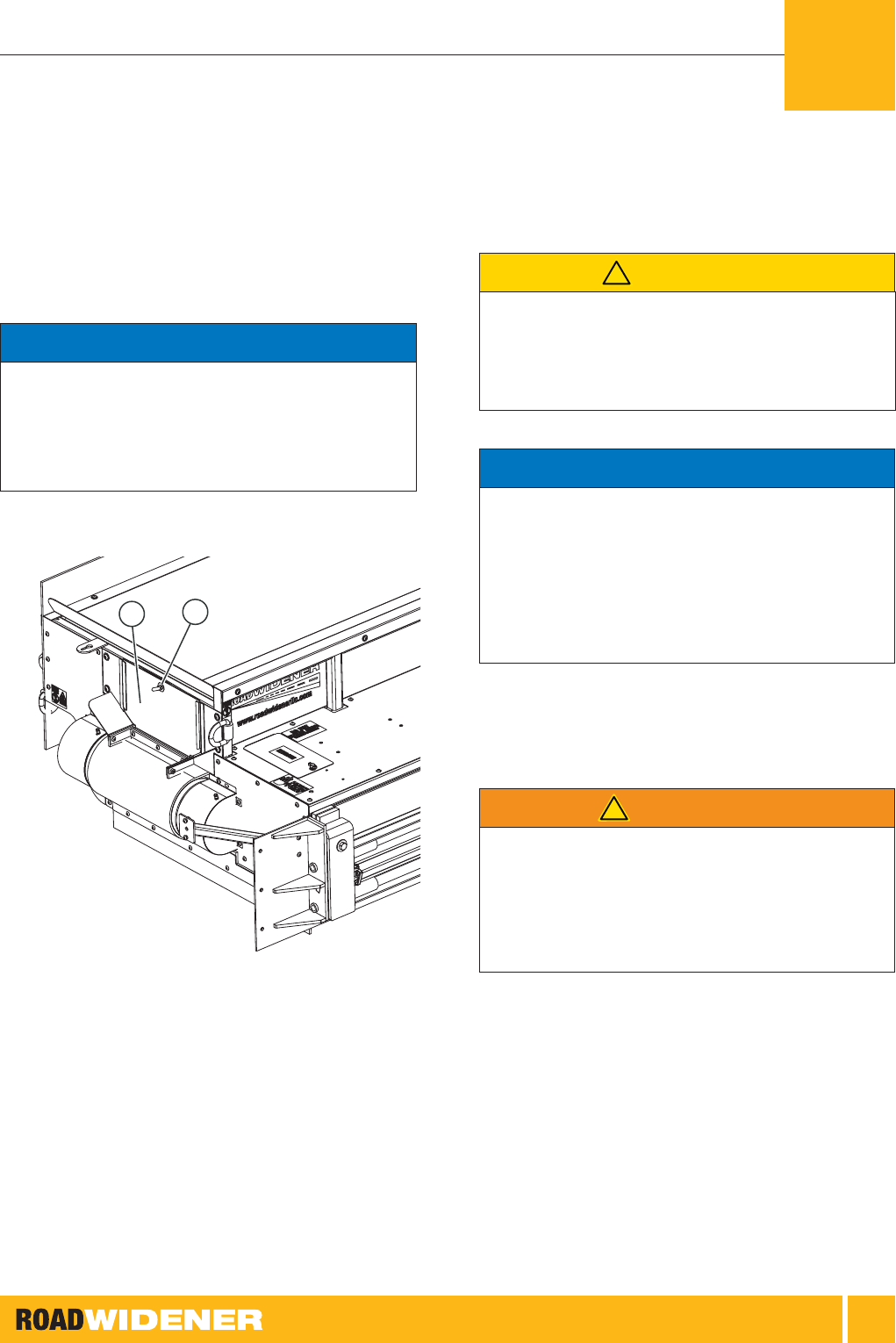
Figure 47: Dual Discharge Unit Hydraulic Valve Location
1 ] Locate the hydraulic valve, which is mounted under
the top cover.
OPERATION - FH-R MODELS (REMOTE UNIT)
5

OPERATOR, MAINTENANCE AND PARTS
43
1
2
3
4
5
6
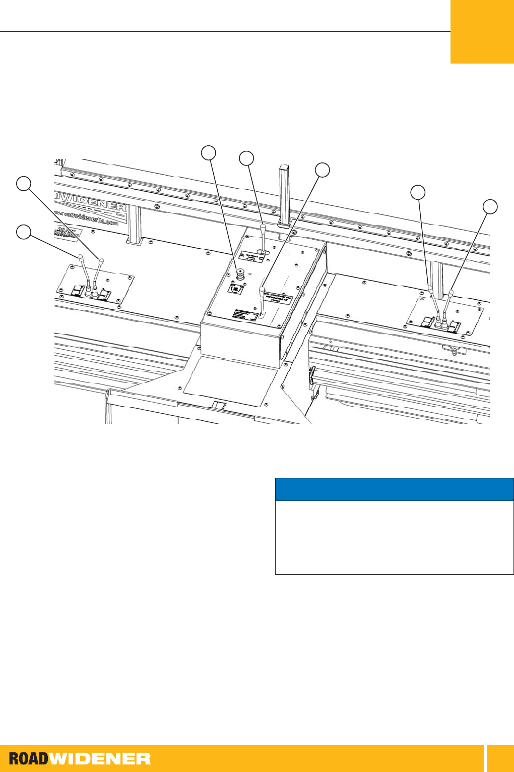
Figure 48: Dual Discharge Unit Hydraulic Valve
1. Conveyor On/Off
2. Conveyor Speed
3. Left Shoe Extend/Retract
4. Left Shoe Up/Down
5. Right Shoe Extend/Retract
6. Right Shoe Up/Down
1
2
3
4
Figure 49: Single Discharge Unit Hydraulic Valve
1. Conveyor On/Off
2. Conveyor Speed
3. Shoe Extend/Retract
4. Shoe Up/Down
OTE: N How the hydraulic lines for the skid steer are
hooked to the Road Widener will affect if the
conveyor moves to the right or the left for
the dual discharge machines. The left and
right direction of the conveyor on the dual
discharge units is determined by the direction
of the hydraulic ow from the skid steer.
Review your skid steer’s operator manual
to determine how to control the direction of
hydraulic ow.
2 ] Locate the solenoid that controls the function that
needs to be overridden by referencing Figure 4848 or
Figure 49 on page 43.
OTE: N For the conveyor ON/OFF and the conveyor
speed override push up and turn the button
a ¼ turn clockwise to release the button from
the detent. When nished, push up and turn
the button a ¼ turn counterclockwise to lock
the button into the detent.
3 ] To override the conveyor On/Off or the conveyor
speed functions, push in on the round pin at the end
of the solenoid.
4 ] To retract the shoe or raise the shoe up, push in on
the round pin at the end of the solenoid.
OTE: N A small object such as an allen wrench can
be inserted in the hole on the end of the
round pin to help pull the round pin out of the
solenoid.
5 ] To extend the shoe or lower the shoe down, pull out
on the round pin at the end of the solenoid.
5
OPERATION - FH-R MODELS (REMOTE UNIT)

OPERATOR, MAINTENANCE AND PARTS
44
Never stand between the truck and the Road
Widener when the truck is backing up. Serious
injury or death could result.
DANGER
!
1 ] Back the truck up to the Road Widener and make
sure the tailgate is properly aligned over the hopper as
close to the machine as possible.
2 ] Apply the parking brake to the truck to hold it in position.
Figure 50: Removing Pins for Push Rollers
3 ] Remove the pins for the push rollers and adjust them
as needed for the type of vehicle being unloaded so
the rollers touch the wheels of the truck.
Figure 51: Rollers Touching Truck Wheels
4 ] The standard roller setup is designed to work with a
quad-axle dump truck with a stone or asphalt tray. The
rollers can be adjusted for many different vehicles by
moving the pins or using the optional roller extensions.
5 ] Make sure the skid steer is lowered and the Road
Widener is parallel to the road surface. Adjust the tilt
on the skid steer if needed.
6 ] Adjust the tailgate chains on each side of the tailgate
so they are both the same length.
1 2 3 4
Figure 52: Levers and Control Knob – FH Models
1. Belt On/Off Lever
2. Slope Up/Down Lever
3. Shoe In/Out Lever
4. Belt Speed Control Knob
OPERATION - FH MODELS (NON-REMOTE UNIT)
5
OPERATOR, MAINTENANCE AND PARTS
45
1
6
7
2
3
4
5
Figure 53: Levers and Controls – Dual Discharge Model
1. Left Slope Up/Down Lever
2. Left Shoe In/Out Lever
3. Belt Speed Control Knob
4. Shoe Selector Control Lever
5. Belt On/Off Lever
6. Right Slope Up/Down Lever
7. Right Shoe In/Out Lever
OTE: N The dual discharge model is equipped with a
check valve in the control valve. Depending
upon your model of skid steer, the ow
control valve for the skid steer must be in
the correct position or the hydraulics for the
Road Widener will not operate.
On the dual discharge model the rubber skirt for the
discharge closure plate should be just touching the conveyor
belt with no material on the belt. Excessive rubbing of the
rubber skirt on the conveyor belt will cause premature wear
on the conveyor belt.
NOTICE
5
OPERATION - FH MODELS (NON-REMOTE UNIT)

OPERATOR, MAINTENANCE AND PARTS
46
1
2
Figure 54: Chute Closure Plate – Dual Discharge Model
1. Screws
2. Closure Plate
7 ] On the dual discharge models install the closure
plate on the side not being discharged on with the 2
screws.
8 ] Push the belt on/off lever up to the ON position. Allow
the belt to run for a couple minutes with the hopper
empty to warm it up.
9 ] Turn the belt speed control knob clockwise to increase
the belt speed and counterclockwise to decrease the
speed.
OTE: N Do not overll the hopper. Overlling the
hopper may cause the conveyor belt to slip
or not turn at all.
10 ] Raise the box and begin to spill material into the
hopper. Do not overll the hopper.
11 ] Make sure the truck park brake is off and the
transmission is in neutral.
OTE: N To keep constant contact of the rollers to the
truck tires, the truck operator may need to
apply slight pressure to the brake pedal.
Never have anyone standing between the Road
Widener and the truck during operation. Serious
injury or death could occur.
WARNING
!
OTE: N On some model skid steers, the auxiliary
hydraulics ow can be controlled by the skid
steer operator, which will allow the conveyor
belt to be started and stopped if required.
12 ] Begin moving forward with the skid steer pushing
the truck.
Build-up of material on the rollers could occur during
operation and should be removed if needed. Excessive build-
up of material on rollers and belt can cause premature wear
and possible belt failure.
NOTICE
OPERATION - FH MODELS (NON-REMOTE UNIT)
5

OPERATOR, MAINTENANCE AND PARTS
47
Figure 55: Bottom Idler Roller Location
13 ] When using the Road Widener with wet material or hot
asphalt, material could build up on bottom idler roller
and the belt.
Figure 56: Material Build-up
14 ] Inspect the rollers for build-up of material before,
during and in between loads while actual operation is
stopped and after operation. Clean up any build-up
before continuing operation.
5
OPERATION - FH MODELS (NON-REMOTE UNIT)

OPERATOR, MAINTENANCE AND PARTS
48
1
2
Figure 57: Rubber Skirt Should Follow Along Edge of Road
1. Rubber Skirt
2. Edge of Road
15 ] Check the position of the material and the rubber skirt.
The material is laying down correctly when the rubber
skirt follows along the edge of the road.
16 ] When traveling, the operator should pay attention to
the hopper to make sure there is not too much or too
little material in the hopper. It may be necessary to
adjust the chains on the tailgate to allow more or less
material out of the truck.
17 ] When traveling, turn the conveyor belt on or off as
needed using the auxiliary hydraulic controls on the
skid steer. Do not allow material to spill over the top of
the shoe.
Figure 58: Ensuring Material is Above Road Surface
18 ] If you are planning to compact the material, make sure
the material is above the road surface. You can adjust
the height of the material by raising or lowering the
boom on the skid steer.
Do not allow the truck to pull away from the Road Widener
with the box up. Damage to the truck or the Road Widener
could occur.
NOTICE
19 ] When the truck is unloaded, stop moving. Have the
truck operator apply the brakes. Lower the truck box
and then have the truck operator pull away.
20 ] Align the next truck and start the process over again.
OPERATION - FH MODELS (NON-REMOTE UNIT)
5

OPERATOR, MAINTENANCE AND PARTS
49
Curb Attachment
Operation
The curb attachment is used to spread material up and
over the back side of the curb. The operation is similar to
standard operation with a few exceptions.
Never operate the shoe hydraulics when the curb attachment
is installed. Damage to the machine will occur if the
hydraulics are used.
NOTICE
1 ] Position the machine so the guide wheel is
approximately 3 inches away from the curb.
1
2
3
Figure 59: Adjusting Chains
1. Pivot Bolt
2. Rear Chain
3. Front Chain
2 ] Make sure the pivot bolt allows the shoe assembly to
move up and down. The shoe assembly must pivot
up and down to follow the contour of the terrain when
spreading material.
3 ] Using the skid steer boom, raise or lower machine so
the shoe is at correct height for the level of material
you want to ll.
4 ] Adjust the front and rear chains to hold the shoe
assembly in place.
1
2
Figure 60: Adjusting the Guide Wheel
1. Wheel Bracket Mounting Bolts
2. Wheel Bracket
5 ] Loosen the 4 bolts holding the wheel bracket to the
frame.
6 ] Move the wheel bracket up or down so the wheel is in
the center of the curb. Tighten the bolts for the wheel
bracket.
5
OPERATION - FH MODELS (NON-REMOTE UNIT)

OPERATOR, MAINTENANCE AND PARTS
50
2
1
Figure 61: Adjusting Shoe Wider
1. Shoe Outside Edge
2. Adjustable Link
7 ] The shoe can be adjusted wider by disconnecting the
front chain and turning the adjustable link to lengthen it.
8 ] Reattach the chain as needed.
9 ] Turn on the conveyor belt and adjust the speed.
10 ] Begin moving forward using the wheel to guide you
against the curb.
11 ] Begin spreading material as you would using the
standard method without the curb attachment.
Disconnecting Hydraulic
Lines
Figure 62: Hydraulic Line Connections
1 ] To disconnect the hydraulic lines, push the male
connector on the hydraulic line into the female coupler.
2 ] Push the sleeve on the female coupler toward the
male coupler.
3 ] Release the hydraulic line from the female coupler.
OPERATION - FH MODELS (NON-REMOTE UNIT)
5

51
Periodic Maintenance Chart
Review the “Safety” Section on page 16 before
performing maintenance.
ITEM DAILY
CHECKS
WEEKLY MONTHLY EVERY YEAR
OR 1,000
HOURS OF
OPERATION
Greasing Machine X X X X
Belt Start-Up and Maintenance X X X X
Check Skid Steer/Wheel Loader Hydraulic Oil Level* X X X X
Check Conveyor Belt Tension X X X X
Hopper Rubber Flashing to Conveyor Belt Clearance X X X
Adjusting Conveyor Belt Drive Chain X X
Checking Hydraulic Hoses X X X
Remote Battery Replacement X X
Clean Machine When Using Gravel X X X
Clean Machine When Using Hot Asphalt X X X X
* See your machine operator’s manual for proper hydraulic oil level check.
MAINTENANCE 6

OPERATOR, MAINTENANCE AND PARTS
52
Maintenance on the Road Widener should only
be performed on a at, level concrete surface.
All hydraulic hoses and electrical connections, if
equipped, should be disconnected from the skid
steer or wheel loader.
WARNING
!
Always be environmentally responsible.
• Follow the guidelines of the EPA or other governmental
agencies for the proper disposal of hazardous materials.
Consult the local authorities or reclamation facility.
• NEVER dispose of hazardous materials irresponsibly
by dumping them into a sewer, on the ground, or into
groundwater or waterways.
• Failure to follow these procedures may seriously harm the
environment.
NOTICE
Performing maintenance on the Road Widener machine
only requires the use of basic hand tools.
Greasing the Machine
The lubrication ttings should be greased daily or more often
if the Road Widener is being used in adverse conditions.
There are a total of 10 grease ttings on the machine, four
for the conveyor bearings and six for the caster wheels.
Figure 63: Lubrication Fittings
MAINTENANCE
6

OPERATOR, MAINTENANCE AND PARTS
53
1 ] Apply grease to the conveyor belt front grease ttings
on each side of the machine.
Figure 64: Front Conveyor Belt Grease Fittings
Figure 65: Rear Conveyor Belt Grease Fittings
2 ] Apply grease to the conveyor belt rear grease tting on
each side of the machine.
Figure 66: Caster Wheel Pivots and Axle Pins
3 ] Apply grease to each of the caster wheel pivots and to
each caster wheel axle pin.
Belt Start-Up and
Maintenance
Properly maintaining your belt will ensure a long belt life
on your attachment. It is essential that you perform the
following steps before use:
1 ] The rst time attaching and connecting your
attachment, run the belt and observe if the belt stays
centered on the head pulley. If there is any “walking” of
the belt, make sure to adjust the conveyor belt tension
on either side of the belt to eliminate the “walking.”
2 ] The rst time you run material through the
machine,run the belt and observe if the belt stays
centered on the head pulley. If there is any “walking” of
the belt, make sure to tighten either side of the belt to
eliminate the “walking.”
3 ] A new belt will stretch with use. Properly maintaining
tension will extend the life of the belt. See manual for
belt maintenance instructions.
4 ] If you run asphalt or wet topsoil through the machine,
it is important to be mindful of the single idler pulley on
the bottom of the conveyor belt. Treat the idler pulley
with a release agent before every load. After use,
clean the idler pulley of any build-up. See steps 13
and 14 on page 47 in the Operation section for more
information.
MAINTENANCE
6

OPERATOR, MAINTENANCE AND PARTS
54
5 ] When using for hot asphalt or wet topsoil, constantly
monitor the belt and the rollers for build-up during
operation and between loads. If material is allowed to
build up on the belt and the rollers it will cause the belt
to be over-tensioned, which could cause premature
belt failure. Tension the belt with the minimum amount
of tension required to allow the belt to turn with no
slippage, ensuring that the belt remains free of build-
up as much as possible. If build-up occurs, stop the
machine and remove build-up and build-up variables
(i.e., get dry soil).
Checking Hydraulic Oil
Level
The Road Widener attachment hydraulic system is lled
at the factory with approximately 3 gallons (11 liters).
During operation the hydraulic uid in the Road Widener is
circulated through the hydraulic system from the skid steer
or wheel loader. The uid level should be checked before
operation.
1 ] Attach the Road Widener to the skid steer or wheel
loader that is going to be used.
2 ] Connect the hydraulic lines and any electrical
connections if required.
3 ] Start up the drive machine and extend and retract the
cylinders for shoe in and out and up and down.
4 ] Run the conveyor belt for approximately 30 seconds.
5 ] Shut down the Road Widener machine and turn off
the skid steer or wheel loader.
6 ] Check the oil in the skid steer or wheel loader
hydraulic system by referring to the procedure in the
machine’s operation manual.
Adjusting Conveyor Belt
Tension
The conveyor belt tension is adjusted from the factory
but may require an adjustment after the machine has
accumulated some run time.
2.5 in.
(63.5 mm)
1 2
Figure 67: Adjusting Conveyor Belt Tension
1. Jam Nut
2. Adjustment Bolt
1 ] Inspect the conveyor belt rollers and make sure there
is no material build-up on the rollers. Clean the rollers
off if necessary.
2 ] Measure the distance from the back of the bearing
plate to the front of the adjustment bracket. Do this on
both sides of the belt. The measurement should be
approximately 2.5 in. (63.5 mm).
3 ] If adjustment is needed, loosen the jam nut for the
adjustment bolt.
4 ] Turn the adjustment bolt until the proper measurement
is obtained. Repeat the procedure for the other side.
The adjustment must be the same for both sides to
ensure the conveyor belt tracks correctly.
MAINTENANCE
6

OPERATOR, MAINTENANCE AND PARTS
55
Hopper Rubber Flashing to
Conveyor Belt Clearance
The hopper rubber ashing should be properly adjusted for
proper operation. If the gap is too wide, material spillage
between the rubber ashing and the conveyor belt can
occur. If the gap is too small, it can cause premature wear
on the rubber ashing and the conveyor belt.
1 ] Inspect the conveyor belt rollers and make sure there
is no material build-up on the rollers. Clean the rollers
off if necessary.
Figure 68: Hopper Rubber Flashing to Conveyor Belt Clearance
2 ] With no material in the hopper, check the clearance
between the rubber ashing and the conveyor belt.
The rubber ashing should be just touching the
conveyor belt with the hopper empty.
3 ] To adjust the ashing, loosen the screws and raise or
lower the ashing. Check the clearance on the entire
length of the hopper and on both sides of the hopper.
4 ] Tighten the screws after the clearance has been
adjusted.
Adjusting Conveyor Belt
Drive Chain
After the rst 10 hours of use, the conveyor belt drive chain
may need to be adjusted. Adjust the conveyor belt drive
chain periodically after the rst adjustment.
2
1
1
Figure 69: Adjust Conveyor Belt Drive Chain after First 10 Hours of Use
1. Mounting Bracket Nuts (4 used)
2. Adjusting Bolt
1 ] Loosen the mounting bracket nuts approximately
1-1/2 turns.
2 ] Loosen the jam nut on the adjusting bolt and turn the
adjusting bolt clockwise to tighten the chain. Do not
overtighten the chain.
3 ] Tighten the jam nut for the adjusting bolt and tighten
the 4 mounting bracket nuts.
MAINTENANCE
6

OPERATOR, MAINTENANCE AND PARTS
56
Checking Hydraulic Hoses
1 ] Check the hydraulic hoses for any noticeable leaks.
Make sure they are not rubbing on any moving parts.
Fix any leaks before operating the equipment.
2 ] Check the hoses for any bulging, cracks, cuts,
abrasions, twisting or bends. Repair or replace hoses
as required.
Cleaning After Operation
Clean out the hopper of any material that is left in it. Make
sure there is no build-up of material on the conveyor belt
rollers. Clean the rollers if needed.
If asphalt was used, make sure debris is properly cleaned
off using a releasing agent.
Remote Battery
Replacement
Figure 70: Remote Battery Cover
1 ] Remove the four screws for the battery cover on the
back of the remote and remove the cover.
MAINTENANCE
6

OPERATOR, MAINTENANCE AND PARTS
57
Figure 71: Battery Replacement
OTE: N Typical temperature range for alkaline
batteries is -20°F to 130°F (-30°C to 55°C). To
achieve maximum performance throughout all
temperature ranges it is recommended that
lithium ion batteries be used.
2 ] Remove the batteries and replace them with a high
quality alkaline AAA battery.
3 ] Install new batteries with negative (-) side of the battery
against the springs.
4 ] Install the battery cover.
MAINTENANCE
6

58
SYMPTOM POSSIBLE CAUSE SOLUTION
Machine tipping or unstable
(All models)
Skid steer or wheel loader
machine are undersized
Check weight capacities of skid steer and use a
larger-sized loader.
The Road Widener hopper is
being loaded on unlevel ground
Load the hopper on level ground with the casters
on the ground.
Road Widener is not on the
caster wheels
Lower the Road Widener so it is resting on the
ground and is level.
Material spilling out of hopper
(All models)
Truck is not properly lined up with
hopper
Properly align truck with hopper.
Push rollers are not adjusted
properly
Adjust the push roller for the truck being
unloaded.
Truck tailgate is open too far Adjust the tailgate chains.
Too much material is in hopper Do not fully ll the hopper.
7
TROUBLE-
SHOOTING

OPERATOR, MAINTENANCE AND PARTS
59
SYMPTOM POSSIBLE CAUSE SOLUTION
No hydraulics Hydraulic hoses are not hooked
up correctly to loader (All models)
Check hose connections and hook up correctly.
Loader’s auxiliary hydraulics are
off (All models)
Make sure the loader’s auxiliary hydraulics are
on.
Control valve levers are not in the
correct position (FH models)
Move the control valve levers to the correct
position.
Flow control valve is not set
properly
Adjust the ow control valve. For FH models see
Figures 36, 37, 56 and 57 and for FH-R models
see Figures 28 and 29.
Remote batteries are dead
(FH-R models)
Replace the batteries.
For dual discharge units, the ow
control selector valve on skid is
not set to correct position
(FH models)
Move the selector valve control switch to the
correct position.
Slow or no hydraulics
(All models)
Possible air in the hydraulic
system
Perform the solenoid manual override for
the shoe extend, and the shoe up or down
solenoids. Continue to override the solenoids
for an additional 7 seconds after the maximum
extension and retraction of the cylinders to allow
the air to be dissipated.
Debris in valve Perform solenoid manual overrides to clear air or
debris from valves.
Low oil in skid steer attachment Check oil and oil pressure from machine
cylinders. They will typically extend more easily
than they retract.
Shoe movement limitation (goes up but
not down, down but not up, out but
not in, in but not out, or a combination
thereof) (FH-R models)
Loose or improper wire
connections
Verify wire connectors are properly connected to
the receiver(s) (brain box).
Defective receiver Swap the wire connectors from each receiver.
Does the problem move to the left side? If yes,
the receiver (brain box) is defective. Replace
receiver. If no, check harnesses. Make sure the
wire harness is not cut or spliced or rubbing on
anything.
TROUBLESHOOTING
7

OPERATOR, MAINTENANCE AND PARTS
60
SYMPTOM POSSIBLE CAUSE SOLUTION
Conveyor belt not moving or slipping
(All models)
Too much material is in the hopper Remove some material from the hopper.
Conveyor belt tension is incorrect Adjust the conveyor belt tension.
Tailgate is open too far and dumping
too much material into the hopper
Shorten the tailgate chains to close the tailgate
more.
Conveyor belt not tracking properly
(All models)
Conveyor belt tension is incorrect Adjust the conveyor belt tension.
Material build-up on the rollers Inspect the rollers and remove any built up
material or debris. Apply a releasing agent to
rollers if needed. See steps 13 and 14 on page
47 for more information.
Too much material is in hopper Remove some material from the hopper.
Loader loses traction when pushing
truck (All models)
Loader is pushing too hard on truck Apply less pressure to the back of the truck.
Too much material is in hopper Remove some material from the hopper.
Brakes on truck are applied too
hard
Apply less brake pressure on truck.
Handheld remote and base unit are
not communicating (FH-R models)
Power is not supplied to base unit
or remote
Make sure the 12-volt DC power cord is
plugged into a 12-volt DC power source and the
connection is clean of debris and corrosion.
Make sure the amber battery LED is not illuminated.
If illuminated, install new batteries in the remote.
The remote green TX LED is not
illuminated or the remote does not stay
connected with the base unit
(FH-R models)
Remote batteries are low Replace remote batteries. See “Remote Battery
Replacement” on page 56.
The remote and the base unit are
powered but are not communicating
with each other (FH-R models)
Remote and base unit may be out
of range
Make sure the units are in range.
Obstructions or interference exist
between remote and base unit
Make sure there is a clear line of sight between
the base unit and the remote.
Remote and base unit are not
properly paired
In the unlikely event that pairing is required,
see the separate pairing instructions that were
supplied with the machine or go to
www.roadwidenerllc.com for the pairing
procedure.
The 12-volt DC accessory socket or
power cord is not rated for 10 amps
Make sure both the 12-volt DC accessory socket
and power cord are rated for 10 amps.
TROUBLESHOOTING
7

OPERATOR, MAINTENANCE AND PARTS
61
SYMPTOM POSSIBLE CAUSE SOLUTION
Red LED on machine is lit but functions
are not working (FH-R models)
The 12-volt DC power source
is not rated for the correct
amperage
The recommended amperage for the
12-volt DC accessory socket is 10 amps. Make
sure the 12-volt DC power source can supply a
minimum of 10 amps.
Remote does not seem to be paired or
will not pair correctly (FH-R models).
12-volt DC power source is not
supplying enough amperage
Check the 12-volt DC power source to make
sure it has the correct output of 10 amps.
TROUBLESHOOTING
7

62
DESCRIPTION PART NUMBER
Conveyer Belt Model:
FH RW-3001135
FHR RW-3001135
FHRD RW-3003004
Prior to 2010 RW-3000082
Hopper Rubber Side Skirt
Highlighted part is the
Rubber Side Skirt
Model:
FH RW-3001131
FHR RW-3001131
FHRD RW-3003005
Note: Order 2 for complete set, one for each side.
8
ILLUSTRATED
PARTS LIST

OPERATOR, MAINTENANCE AND PARTS
63
DESCRIPTION PART NUMBER
Hopper Steel Retaining Side Strip
Highlighted parts are
the Retaining Side
Strips
Model:
FH RW-3001129
FHR RW-3001129
FHRD RW-3003006
Note: Order 2 for complete set, one for each side.
Hopper Rubber End Skirt
Highlighted part is the
Rubber End Skirt
Model:
FH RW-3001132
FHR RW-3001132
FHRD N/A both sides of hopper open
8
ILLUSTRATED PARTS LIST

OPERATOR, MAINTENANCE AND PARTS
64
DESCRIPTION PART NUMBER
Hopper Steel Retaining End Strip
Highlighted part is the
Retaining End Strip
Model:
FH RW-3001130
FHR RW-3001130
FHRD N/A both sides of hopper open
Hopper Bumper Outer Wrap
Highlighted parts are
the Bumper Outer
Wrap
All Models: RW-3001178
Note: Order 2 for complete set, one for each side.
8
ILLUSTRATED PARTS LIST

OPERATOR, MAINTENANCE AND PARTS
65
DESCRIPTION PART NUMBER
Hopper Bumper Inner Reinforcement All Models: RW-4005066
Note: Order 4 for complete set, 2 for each side. These parts go
on the inside of the Bumper Outer Wrap RW-3001178.
See Hopper Bumper Outer Wrap on page 64.
Exit Chute Rubber Flashing Strip
Highlighted parts are
the Exit Chute Rubber
Flashing
All Models: RW-3000023
Note: The Exit Chute has 2 sides.
For FH & FHR Models order 2 for complete set.
For FHRD Model order 4.
Exit Chute Steel Retaining Strip
Highlighted parts are
the Exit Chute
Retaining Brackets
All Models: RW-3000024
Note: The Exit Chute has 2 sides.
For FH & FHR Models order 2 for complete set.
For FHRD Model order 4.
8
ILLUSTRATED PARTS LIST

OPERATOR, MAINTENANCE AND PARTS
66
DESCRIPTION PART NUMBER
Apron Rubber Skirt
Highlighted part is the
Apron Rubber Skirt
All Models: RW-3001075
Apron Mounting Strips – Steel
Highlighted parts are
the Apron Mounting
Strips
All Models: RW-3001149
Note: Order 2 to attach Apron Skirt.
Indicator Light All Models: RW-4004068
8
ILLUSTRATED PARTS LIST

OPERATOR, MAINTENANCE AND PARTS
67
DESCRIPTION PART NUMBER
Caster All Models: RW-4000004
Head Pulley Assembly
All Models: RW-2001003
Idler Roller
All Models: RW-4000017
8
ILLUSTRATED PARTS LIST

OPERATOR, MAINTENANCE AND PARTS
68
DESCRIPTION PART NUMBER
Hydraulic Motor All Models: RW-4000005
Hydraulic Motor Mounting Bracket
All Models: RW-3001122
8
ILLUSTRATED PARTS LIST

OPERATOR, MAINTENANCE AND PARTS
69
DESCRIPTION PART NUMBER
Shoe Frame Assembly All Models:
Right Hand RW-2001000
Left Hand RW-2002000
Shoe Catch
Model:
FH Right Hand RW-3001112
FH Left Hand RW-3002030
FHR Right Hand RW-3001112
FHR Left Hand RW-3002030
FHRD Right Side RW-3003044
FHRD Left Side RW-3003045
Wear Strip not included with this part
8
ILLUSTRATED PARTS LIST

OPERATOR, MAINTENANCE AND PARTS
70
DESCRIPTION PART NUMBER
Wear Strip All Models: RW-3001113
Large Sprocket
All Models: RW-4000008
8
ILLUSTRATED PARTS LIST

OPERATOR, MAINTENANCE AND PARTS
71
DESCRIPTION PART NUMBER
Small Sprocket (Motor Sprocket) All Models: RW-4000020
Needs a Sprocket Key RW-3001139
Belt ON/OFF Control Valve
FH Model: RW-4000037
8
ILLUSTRATED PARTS LIST

OPERATOR, MAINTENANCE AND PARTS
72
DESCRIPTION PART NUMBER
Slope/Shoe Control Valve FH Model: RW-4000038
Belt Speed Control Valve
FH Model: RW-4000016
8
ILLUSTRATED PARTS LIST

OPERATOR, MAINTENANCE AND PARTS
73
DESCRIPTION PART NUMBER
Remote Control Receiver Models:
FH Not Applicable
FHR 3120 and Older RW-4005064
FHR 3121 and Newer RW-4003000
FHRD 1089 and Older RW-4005065
FHRD 1090 and Newer RW-4003001
Single Remote Control
Models:
FH Not Applicable
FHR RW-4005019
FHRD Not Applicable
8
ILLUSTRATED PARTS LIST

OPERATOR, MAINTENANCE AND PARTS
74
DESCRIPTION PART NUMBER
Dual Remote Control Models:
FH Not Applicable
FHR Not Applicable
FHRD RW-4005020
8
ILLUSTRATED PARTS LIST

Road Widener LLC
Sales: 844-4WIDENER (844-494-3363)
sales@roadwidenerllc.com
www.roadwidenerllc.com
Made in the USA.
